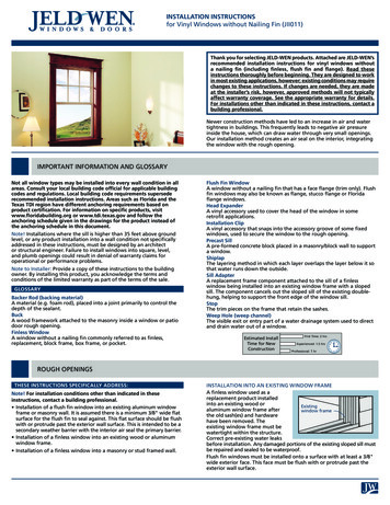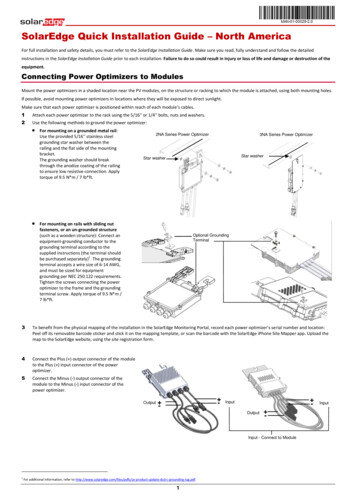
Transcription
INSTALLATION INSTRUCTIONS"Elevate your storage needsto a Higher Level"MODEL # ASL-500Aladdin Storage Lift, LLC.61 ShieldsAladdinStorageRoadLift, LLC.8370Wolf Lake Drive,Suite 112Huntsville,AL 35811Memphis, TN 38133Phone (256) 429-9700Phone (901) 385-0456Fax (256) 429-9708Fax (901) 385-0533www.aladdinstoragelift.comREV# 4.0www.aladdinstoragelift.com
Convenient & ReliableThe Aladdin Storage Lift is a motorized liftsystem that easily and safely lifts your storage items into the atticor lowers them down to floor level. It eliminates the difficult, timeconsuming and dangerous task of lifting or pushing items up anddown a pull down stairway.The Storage Lift turns a difficult task into a simple andeconomical solution for all of your storage needs.
TABLE OF CONTENTSWarnings and Safety PrecautionsPage 1Features and Benefits Page 3Operating Guide Page 4Installation Guide Page 5Troubleshooting Page 27Warranty Card Page 29
WARNINGS AND SAFETY PRECAUTIONSThe following statements are warnings and safety precautions for the installation, operation, andmaintenance of the Aladdin Storage Lift. Failure to understand and follow each of the warningsand safety precautions below could cause death, personal injury, and/or property damage.Closely follow the installation guide when installing the Aladdin Storage Lift. Please contacttechnical support (877) 287-4601 with any questions or concerns regarding the following:1. Every installation is different. Consult a structural engineer to confirm installationand load capacity of the ASL500 can be safely supported by existing structure.2. The Aladdin Storage Lift should never be used to transport humans in any way.3. Do not install a storage lift where there is no human access to the attic such as an atticpull down or staircase.4. The ceiling height must be specified when ordering the Aladdin Storage Lift.5. Never allow the cart cable counter weights to touch the floor. If the counter weightstouch the floor, the cables will not wind properly. Contact Aladdin Storage Lift technicalsupport for assistance. (877) 287-46016. Avoid damage to the ceiling, storage lift, and load by making sure the load placed insidethe cart assembly does not extend outside the inner frame.7. Do not load the cart assembly with more than 500lbs.8. Do not install the storage lift outdoors.9. The storage lift must be framed in on a level plane.10. Never sit or stand under the cart assembly while operating the storage lift.11. Never operate the Aladdin storage lift without the cart assembly attached to the cartcables. This can cause the cart cables to jump off the Drive Shaft, causing a safety hazard.If this situation occurs, contact Aladdin Storage Lift technical support immediately.(877) 287-460112. Never fully extend the cart cables from the Aladdin Storage Lift. This could cause thecable to become reversed on the Drive Shaft. See owner’s manual for supplied cablelength.13. Disconnect the power source from the storage lift when servicing or performingmaintenance.1
WARNINGS AND SAFETY PRECAUTIONS14. Never cut or adjust the length of the cart cables.15. Make sure the height of your load does not exceed the attic ceiling height.16. Never install an Aladdin Storage Lift where the ceiling height exceeds the cart cablelengths. This can cause the cart cables to become reversed on the Drive Shaft, causinga safety hazard. If this situation occurs, contact Aladdin Storage Lift technical supportimmediately. (877) 287-460117. Do not operate the storage lift unless the cart cables are in the Drive Shaft spool grooves.18. Periodically inspect the cart cables for frays or kinks. If a fray or kink is detected, contactAladdin Storage Lift technical immediately. (877) 287-460119. Periodically inspect the worm gear drive and replace the axel grease if necessary.20. Periodically inspect the ‘plunger style’ Limit Switch and make sure the screws are tight.21.Do not install a storage lift where the load height will exceed the attic ceiling height.22. Never alter the Aladdin Storage Lift from its original state.2
FEATURES AND BENEFITSEasy to InstallThe Aladdin Storage Lift is neatly tucked away in the area above the ceiling. The only visibleindication of the system is the neatly trimmed out box in the ceiling. Installation by your trimcarpenter/framer and electrician is simple, in both new construction and existing homes. Oncein place, you can raise your storage items into the attic from floor level safely, without having tocarry them up the attic stairs. You MUST specify the ceiling height when ordering yourAladdin Storage Lift.Designed for Years of Trouble-Free OperationThe Aladdin Storage lift is designed for years of trouble-free operation. The system has beenrigorously tested and uses the latest technology for electrical components and safety systems.Loads up to 500lbs are no problem for the Aladdin Storage Lift.WarrantyThe Aladdin Storage Lift is backed by a full 5-year limited warranty on all parts andcomponents.Keyswitch ControllerThe Keyswitch Controller is used to operate the Aladdin Storage Lift. This simple to usekeyswitch puts the storage lift’s controls at your fingertips.3
OPERATING GUIDEQuick Notes:a.b.c.d.e.f.Never allow the cart cable counter weights to touch the floor.The ceiling height must be specified when ordering the Aladdin Storage Lift.Never allow a child to operate the storage lift.While operating the storage lift, keep the Cart Assembly in sight to make sure itshuts down properly.The Aladdin Storage Lift should never be used for the movement of humans.If the storage lift is not operating properly, contact Aladdin’s Storage Lift’stechnical support at (877) 287-4601.Perform the following for operation:1.Insert key into keyswitch.2.Turn and hold the keyswitch to the right to run your storage lift down to the FLOORPOSTION.3.Release the keyswitch once the cart touches the floor. Do not allow cable counter-weightsto touch the floor. Load the items that you want to transport to the attic inside thecart assembly. Do not allow any items to hang over the inner frame of the cart.4.Turn and hold the keyswitch to the left to run your storage lift up to the CEILINGPOSITION, then release.To stop the storage lift from lowering at any time, release the keyswitch. To stop the storage liftfrom raising at any time, release the keyswitch.Enjoy using the Aladdin Storage Lift to make all of your attic storage needs much easier!4
INSTALLATION GUIDEDisconnect the power when servicing or performing maintenance to the AladdinStorage Lift. Electricity can kill!GETTING STARTED:1. This installation guide is for the Aladdin Storage Lift which is rated to handle up to a500lb load. Do not exceed a 500lb load.2. Only install this lift system where there is ample space between the roof rafters andattic floor joists. Do not lift loads into the attic that are taller than the attic. This will causedamage to the loads, the storage lift, the roof, and the ceiling.3. Study the ‘Warnings and Safety Precautions’ section in the owner’s manual.4. Read the ‘Installation Guide’, studying the drawings carefully, and learn each part andstep before installing the Aladdin Storage Lift.5. The Aladdin Storage Lift frames, chassis, and supports should be installed by alicensed framer or trim carpenter. All line and low voltage electrical work should beperformed by a licensed electrician. Consult a structural engineer to confirm installationand load capacity of the ASL500 can be safely supported by existing structure.6. Open the boxes and examine the parts received. Included should be the following:Motor drive assembly, drive shaft, end plates, cart cables, cart assembly, supportstraps, limit switches, hardware, wiring, ceiling support frame, cart springs, and aKeyswitch Controller.INSTALLATION TIPS:1. When installing the Motor Drive Assembly and the Bearing Plate Assembly, themeasurement of 74 ¾ inches center to center between the frames is crucial for DriveShaft alignment. See STEP 8.2. When reinstalling pulley wheels and spacers after feeding cart cables, DO NOT overtighten ½ inch bolt. See STEP 10.3. On Motor Drive Assembly side, make sure the cables are feeding over the top of the CableSafety Switch Bar. See STEP 10.4. Alignment of the cart cables on the helical grooving of the Drive Shaft is essential forsmooth operation of the Storage Lift. See STEP 18.5. Make sure the cables are rolling off the top of the spools. See STEP 10 & 15.6. Make sure the cable is inserted in the Motor Shutoff Switch Bar. See STEP 14.MATERIALS NEEDED:1. One sheet of 3/8 plywood cut to 68 ½” x 44”.2. One sheet 1/4 finished plywood cut to 83 ½” x 48” (not to exceed 20 lbs).5
STEP 1-Framer or Trim CarpenterDetermine where the storage lift will be installed. The storage lift should be in a place wherethere is ample ceiling height in the attic. Have a licensed electrician or plumber reroute anywiring or pipes that may be in or around the area where the storage lift will be installed.Measure an area of 85”x 46 ½”. If your attic floor has joists that are 24” on center, you’ll need toremove one partial joist. If your attic floor has joists that are 16” on center, you’ll need to removetwo partial joists. DO NOT cut them until step #2 is completed. Remember, the insidemeasurements should be 82” x 46 ½” after the short side support joist are installed.6
STEP 2-Framer or Trim CarpenterInstall the ceiling support straps as shown below. Use eight straps for joist that are 16” on centerand six straps for joists that are 24”on center. Use the supplied 1/4”x 1 ½” hex lag screws and1/4” fender washers for mounting. Temporarily support the joists from underneath.7
STEP 3-Framer or Trim CarpenterAfter remeasuring the joists and installing the ceiling support straps, temporarily support thejoists from underneath, remove the ceiling joists. Cut out any sheetrock if present and removeany insulation. Remember, the inside measurements should be 82”x 46 ½” after the short sidesupport joist are installed.8
STEP 4-Framer or Trim CarpenterInstall short side support joists on the 46 ½” ends. Material not supplied. Assure the opening isperfectly square. The inside dimensions of the opening should be 82”x 46 ½”. Temporarybottom support may now be removed.STEP 5-Framer or Trim CarpenterTrim out the opening in the ceiling to match the style of the room using 3/4” thick trim.Material not supplied. The trim should be mounted flush with the edge of the joist andsheetrock. Make sure trim does not hang over inside of opening so it will not interfere with theoperation of the Storage Lift.9
STEP 6-ElectricianInstall Motor Drive Assembly. The assembly should be installed on the opposite side of the loadretrieval side. The Motor Drive Assembly MUST remain to the outside of the opening. Theassembly should be installed directly on top of joist, not on top of attic flooring. TIP-The use ofQuick Clamps is helpful to temporarily secure frame to joist.10
STEP 7-ElectricianInstall the Drive Shaft in the Motor Drive Assembly. Secure the Drive Shaft with the supplied3½”x ½” bolt and nylon insert locknut.11
STEP 8-ElectricianInstall the Bearing Plate Assembly after inserting the Bearing end of the Drive Shaft into theBearing Plate. The assembly should be installed directly on top of joist, not on top of atticflooring. Assure both the Drive end and Bearing end are perfectly square with the ceiling joists.The overall dimension center to center should be 74 ¾ ”. Measure this dimension from all fourcorners of the assembly. This measurement is crucial to keep the cable spools on the Drive Shaftin line with the pulleys on the Motor Drive and Bearing Plate Assembly’s.12
STEP 9-ElectricianBefore mounting to the joists, make sure Storage Lift Assembly is centered in the opening.Four angle bracket holes are provided on each flange, use two that line up with a solid part ofthe structure. Drill 5/8” holes in the ceiling joists using the angle bracket holes as guides. Usingthe supplied 1/2” x 4” bolts, 1/2” fender washers, and 1/2 ” nylon insert lock nuts, mount theMotor Drive Assembly and Bearing Plate Assembly to the ceiling joists. Tighten bearing setscrews with 3/16 allen wrench.13
STEP 10-ElectricianFeed the cart cables through the pulleys. The outboard cart cables will feed through the 1stpulleys and across the opening to the 2nd pulleys, then down. The inboard cart cables will feedover the 1st pulleys, then down. To feed the outboard cart cables, the 2nd pulleys andspacers will need to be removed. To remove, take the ½”x 5 ½” bolts loose to release the pulleysand spacers from the Motor Drive and Bearing Plate Assembly. Feed cables then reinstall pulleys and spacers making sure that they are in the correct order to align the 2nd pulleys with the1st pulleys. When reinstalling 1/2” bolts, DO NOT over tighten the bolts as it will squeezethe pulley mounting brackets into the pulleys and spacers. This will bind the pulleys causingthem not to rotate properly. Tighten the bolt so that it has minimal side to side play and it canbe rotated by hand. Note: On Motor Drive Assembly side, make sure the cables are feedingover the top of the Cable Safety Switch Bar installed on Step 15. Make sure the cables arerolling off the top of the spools. (See picture below)***Cables should roll offthe top on the spools***STEP 11-ElectricianAssemble cart, lower cart and ceiling panel support14
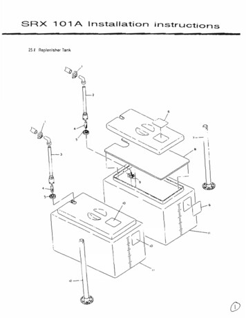
STEP 12-ElectricianAttach the Lower Cart Assembly to the Upper Cart Assembly using the supplied #10 x 1 ½”screws and nuts. The Cart Assembly is adjustable for different joist and truss sizes. Attach theLower Cart Assembly to the Upper Cart Assembly in the proper adjustment holes per your joistor truss size. The adjustment holes are as follows from top to bottom: 2 x 8, 2 x 10, 2 x 12, 2 x14, and 2 x 16.CABLE2’ X 10’ JOIST2’ X 12’ JOISTTHREADED CABLE END2’ X 8’ JOIST2’ X 16’ JOIST2’ X 14’ JOISTCABLE COUNTERWEIGHTNUT17
STEP 13-ElectricianAttach the Cart Cables to the Cart Assembly. Position the Cart Assembly on the floorunderneath the storage lift so that the 1st pulleys use the inner Cart Cable attachment holes andthe 2nd pulleys use the outer Cart Cable attachment holes. Attach the Cart Cables to the CartAssembly by sliding the threaded ferrule that is attached to the end of the Cart Cables throughthe holes in the Cart Assembly and then through the Cable Counter Weights and fasten withthe supplied 1/4” nylon insert lock nuts. ** Do not thread nylon lock nuts to far up threadedferrule. Only two threads should be showing below the nylon lock nut**CABLE2’ X 10’ JOIST2’ X 12’ JOISTTHREADED FERRULE2’ X 14’ JOIST2’ X 8’ JOISTCABLE COUNTERWEIGHT2’ X 16’ JOIST18NUT
STEP 14-Electrician - Important Safety StepFollowing the pictures below, insert the Cart Cable into the Motor Shutoff Switch Bar.After inserting the Cart cable into the Motor Shutoff Switch Bar, cut the ziptie holding the Bar.Remove and discard ziptie.Note: Take care cutting the ziptie as to not damage Motor Shutoff Switch Bar or Cart Cable.19
STEP 15-ElectricianMount safety switch to drive side frame with supplied #8 x 1” self tapping screws. There aretwo pilot holes showing location. Note: Make sure the cables are feeding over the top of theCable Safety Switch Bar.STEP 16-ElectricianMount the Keyswitch Controller in a single gang box. It should bemounted in an area that will be visible from the lowered Cart Assembly.Run the supplied low voltage control wire from the control board to theKeyswitch Controller.20
STEP 17-ElectricianApply a dedicated 110 volt hot and neutral to the power supply box on the Motor DriveAssembly. There is a three foot long 14/2 Romex already prewired to the service switch fromthe factory.21
STEP 18-ElectricianAssure cart cables are riding in the pulley grooves before testing the storage lift. At this time itwill also be necessary to align the cart cables on the helical grooving of the Drive Shaft. Testthe operation of the storage lift and align the cart cables using the following steps:a.Unplug the low voltage control wire from the control board terminal. SeeDiagram A belowb.Using a jumper wire, jumper between the COM and UP pins on the control boardterminal. The motor should start to raise the cart cables. Continue to raise thecables until the cart cable counter weights leave the floor and put tension on thecables. Stop raising before the cart cables ‘pick up’ the Cart Assembly off the floor.c.Align the cart cables on the helical grooving of the Drive Shaft. All four cablesmust be aligned the same way. Start by placing the first wind of each cable in thefirst helical groove, second wind in second helical groove and so on. Keep in mindon each end of the Drive Shaft the first layer of each cable winds towards thecenter cable divider. If the cables are not aligned properly the Storage Lift will notoperate smoothly. See Diagram B belowd.Using a jumper wire, jumper between the COM and UP pins on the control boardterminal and raise the Cart Assembly off the floor, manually press the MotorShutoff Switch Bar to ensure the automatic shutoff system will work.e.Using a jumper wire, jumper between the COM and DOWN pins on the controlboard terminal. The motor should lower the Cart Assembly.f.If the motor properly raises and lowers the Cart Assembly, plug the low voltagecontrol wire back on to the control board terminal.g.Test the storage lift by testing the Keyswitch Controller. Wait 2 seconds betweeneach command.h.Contact Aladdin Storage Lift’s technical support if any of these steps do not work.(877) 287-4601TIP-After the cart cables have been aligned on the Drive Shaft, never allow the cart cablecounter weights to touch the floor while operating the Storage Lift or the cart cables will haveto be realigned.Diagram ADiagram B22
STEP 19-ElectricianFor safety, install the sheet metal covers as shown in Diagram A and B.For the motor cover use the supplied 1/4” x 1/2” hex bolts (see Diagram A).For the drive side inside and outside coversuse the supplied #8 x 1/2” truss washer, self tappingscrews (see Diagram A).For the bearing side inside and outside covers use the supplied #8 x 1/2” truss washer, self tapping screws (see Diagram B).MOTOR COVERDRIVE SIDEINSIDE COVERDRIVE SIDEOUTSIDE COVERBEARING SIDEOUTSIDE COVERBEARING SIDEINSIDE COVER23
STEP 20-Framer or Trim CarpenterMake a Ceiling Panel using a sheet of 1/4” finished plywood. Cut it to a dimension of83 ½” x 48”. Use the supplied #8 x 1/2” self tapping screws to attach the Ceiling Panel to theCeiling Panel Support. Install a screw at each point as shown in the picture below.ATTN: The Ceiling Panel should not exceed 20 lbs.24
STEP 21-Framer or Trim CarpenterUsing the supplied Ceiling Panel Support Springs, attach the Ceiling Panel Support to thebottom of the Cart Assembly. The springs hook through the holes provided in the bottom ofthe Cart Assembly and Ceiling Panel Support. Install all springs with the hooks facing the sameway.STEP 22-Framer or Trim CarpenterAttach a 68 ½” x 44” sheet of 3/8” plywood to the Cart Assembly. Screw it to the Cart Assembly using the supplied #8 x 1” self tapping screws.25
STEP 23-Framer or Trim CarpenterOperate the storage lift. Enjoy the ease of lifting your storage items into your attic.26
TROULBESHOOTING GUIDEThe Aladdin Storage Lift was built and adjusted at the factory to operate safely withoutmaintenance for many years. To perform properly, the storage lift MUST be installed exactlyaccording to the installation guide. Should a problem arise, simply follow this troubleshootingguide to determine the fix. If the situation can not be remedied, contact Aladdin’s Storage Lift’stechnical support at:(877) 287-4601Warning: Line voltage is exposed when the toggle switch in the power supply box is turnedon. Electricity can kill!If the storage lift is not running properly:1. Make sure the switch in the power supply box is turned on. The switch is on theMotor Drive Assembly. If not on, turn it to the on position and retry the storage lift.Proceed to #2 if still not working.2. Turn power off, remove fuse and do a continuity test on the fuse on the control board. Thecontrol board is located on the Motor Drive Assembly. If the fuse is blown, replace with a7 amp, 250 volt fast act fuse. Proceed to #3 if fuse is good and still not working.3. Remove the low voltage control wire from the control board. Using a jumper wire,jumper between the COM and DOWN pins. If the Cart Assembly starts to lower,jumper between the COM and UP pins. If the lift works, proceed to #4. If the liftdoes not work, proceed to #5.4. Plug the low voltage control wire back on to the control board. Locate the SmartLiftController and remove it from the wall. Unplug the low voltage control wire from theback of the SmartLift Controller. Using a jumper wire, jumper between the BLACKand GREEN wires in the control wire to lower the Cart Assembly. Jumper between theBLACK and RED wires to raise the Cart Assembly. If the lift operates properly,familiarize yourself with the SmartLift Controller Guide or replace the SmartLiftController. If not, replace the low voltage control wire. Call Aladdin for parts.(877) 287-46015. Perform a Limit Switch bypass by unplugging the purple, orange, and brown Limit Switchwires from the control board. Fix a temporary jumper wire between the COM and NClimit switch terminals. Using a jumper wire, jumper between the COM and DOWNpins. If the Cart Assembly starts to lower, jumper between the COM and UP pins. If thelift works, replace the Motor Shutoff Switch. Call Aladdin for parts or if yourstorage lift is still not working. (877) 287-460127
IILUSTRATION “A”CONTROL BOARD28
WARRANTY AGREEMENTAladdin Storage Lift, LLC warrants its storage lift for five years from the date of purchase. Thewarranty includes all parts provided the lift is installed properly by a licensed carpenter andelectrician. Labor charges will be the responsibility of the purchaser.If the storage lift does not operate properly, the purchaser must contact a factory authorizedservice technician approved by Aladdin Storage Lift, LLC to determine if the storage lift wasinstalled properly. The technician will furnish a written report to the purchaser and Aladdinconcerning any problem with the lift system which will be binding on all parties concerned.All defective parts must be returned to Aladdin Storage Lift, LLC for the warranty to apply.Any alteration or by-passing of the electrical or mechanical system will void the warranty andcan result in a safety hazard.The warranty agreement showing the date of purchase and distributor must be returned toAladdin Storage Lift, LLC within 30 days of purchase to validate the warranty. Call yourdistributor to obtain the name of a factory authorized technician in your area.DistributorInstallerHome OwnerAddressTelephoneDate of Purchase29
The Aladdin Storage lift is designed for years of trouble-free operation. The system has been rigorously tested and uses the latest technology for electrical components and safety systems. Loads up to 500lbs are no problem for the Aladdin Storage Lift. Warranty The Aladdin Storage Lift is

