Transcription
— GRIT —Guardrail InstallationTraining ManualProcedures and Practices forthe Installation, Replacement,and Repair of GuardrailRevised–November 2013
Table of ContentsGRIT Manual – v. 2.0TABLE OF CONTENTSCHAPTER 1: INTRODUCTIONA. The Need for Barrier Training . 1-1B. Clear Zone . 1-1C. Barrier Warrants. 1-4D. Barrier Flare Rates . 1-6E. Length of Need . 1-7F. Guardrail Testing Requirements . 1-10G. Deflection . 1-10H. Soil Backing . 1-12I. Barriers on Slopes . 1-12J. Measuring the Height of Guardrail Systems . 1-14K. Curb Use with Guardrail . 1-15CHAPTER 2: STANDARD GUARDRAIL SYSTEMSA. Guardrail Requirements . 2-1B. VDOT Guardrail Systems . 2-11. VDOT GR-3. 2-12. VDOT GR-8, GR-8A, GR-8B, GR-8C . 2-23. VDOT GR-2, GR-2A . 2-34. VDOT MB-5, MB-3 . 2-4CHAPTER 3: GUARDRAIL TRANSITIONSA. Weak Post Cable to Strong Post W-beam (GR-3 to GR-2) . 3-1B. Weak Post W-beam to Strong Post W-beam (GR-8 to GR-2). 3-1C. Strong Post W-beam to Rigid Object (GR-2 to GR-FOA) . 3-2D. Guardrail Attachment to Temporary Concrete Barrier . 3-4E. Reducing W-beam Guardrail Deflection . 3-4We Keep Virginia Moving!
Table of ContentsGRIT Manual – v. 2.0CHAPTER 4: GUARDRAIL TERMINALSA. NCHRP 350 Terminal Requirements . 4-1B. NCHRP 350 Approved Terminals . 4-11. Cable Terminals (GR-3) . 4-12. Weak Post W-beam Terminals (GR-8 Type II) . 4-23. Strong Post W-beam (GR-6, GR-7, GR-9) . 4-24. Median Barrier Terminal (GR-9) . 4-55. Terminals for Curbed Sections . 4-66. Trailing End Terminals (GR-11) . 4-67. Bullnose Terminal . 4-7C. Gaps Between Barrier Runs . 4-7D. Site Preparation . 4-7E. Breakaway Cable Anchorage Information. 4-10CHAPTER 5: SPECIAL GUARDRAIL TREATMENTSA. Guardrail at Low Fill Culverts (GR-10) . 5-1B. Extra Blockouts (GR-INS). 5-1C. Special Designs . 5-1D. High Tension Cable Systems . 5-1CHAPTER 6: BARRIER DELINEATIONA. Longitudinal Runs . 6-1B. Terminals . 6-1CHAPTER 7: GUARDRAIL INSTALLATION REFERENCESAPPENDIX 1: NOTED PROBLEMS / ACRONYMS & GLOSSARYAPPENDIX 2: GUARDRAIL STANDARDS.We Keep Virginia Moving!
List of Figures and TablesGRIT Manual – v. 2.0LIST OF FIGURES AND TABLESFIGURE 1: COMPARATIVE RISK WARRANTS FOR EMBANKMENTS . 1-5FIGURE 2: DESIGN APPROACH BARRIER LAYOUT VARIABLES (LON) . 1-8FIGURE 3: FIELD APPROACH BARRIER LAYOUT VARIABLES (LON) . 1-9FIGURE 4: RECOMMENDED BARRIER PLACEMENT FOR OPTIMUMPERFORMANCE . 1-11FIGURE 5: RECOMMENDED W-BEAM BARRIER LOCATION ON 6:1SLOPE . 1-13FIGURE 6: GUARDRAIL HEIGHT RELATIVE TO EDGE OF SHOULDER . 1-14FIGURE 7: STANDARD GR-3 TO STANDARD GR-2 TRANSITION . 3-1FIGURE 8: STANDARD GR-8 TO STANDARD GR-2 TRANSITION . 3-1FIGURE 9: STANDARD GR-FOA-1 . 3-2FIGURE 10: STANDARD GR-FOA-2 . 3-3FIGURE 11: STANDARD W-BEAM TERMINAL CONNECTOR (GR-HDW) . 3-3FIGURE 12: REDUCING W-BEAM GUARDRAIL DEFLECTION (GR-INS) . 3-4FIGURE 13: SUGGESTED ROADSIDE SLOPES FOR APPROACHBARRIERS . 4-9FIGURE 14: SPECIAL TRAFFIC BARRIER W-BEAM END TREATMENTGRADING ADJUSTMENT . 4-12FIGURE 15: BREAKAWAY SUPPORT OR SOIL TUBE STUB HEIGHTMEASUREMENT . 4-13FIGURE 16: NESTING OF W-BEAM RAIL FOR LEFT OUT POST (GR-10) . 5-2TABLE 1:FIRST HARMFUL EVENT FIXED-OBJECT FATALITIESBY OBJECT TYPE . 1-2TABLE 2:CLEAR ZONE DISTANCES . 1-3TABLE 3:DESIGN PARAMETERS FOR ROADSIDE BARRIER LAYOUT . 1-6We Keep Virginia Moving!
Chapter 1GRIT Manual – v.2.0CHAPTER 1INTRODUCTIONWe Keep Virginia Moving!
Chapter 1GRIT Manual – v.2.0CHAPTER 1INTRODUCTIONA. NEED FOR BARRIER TRAINING1. Fatalities per year/ROR fatalities – Annually, there are approximately 40,000fatalities on our nation’s highways; nearly 12,000 of them occur as a result of run-offthe-road (ROR) crashes.2. Guardrail fatalities - Approximately 1,200 of the ROR fatalities are caused byguardrail as the first harmful event (see Table 1).3. In Virginia, typically about 60% of the roadway crashes are ROR crashes.4. Virginia’s Strategic Highway Safety Plan is committed to reduce yearly fatalitiesand serious injuries due to crashes.5. Requirements for the application of guardrail systems, as well as the installationinstructions for numerous guardrail devices, are becoming more complex.6. Barrier standards and specifications are constantly changing based on vehicle designsand popularity which affects the functionality of the various guardrail systems.Testing criteria changes are also made based on vehicle designs.B. CLEAR ZONEClear zone definition: The total roadside border area, starting at the edge of the traveled way,available for safe use by errant vehicles.1. There is NO “Magic” 30-foot clear zone. This distance was used in the PAST.2. Each location has to be reviewed and the Clear Zone calculated. - Based onexperience in the 1960's at the General Motors Proving Grounds using good vehicles,experienced drivers, a familiar route and flat terrain; nearly 20 percent of the vehiclesleaving the traveled way (about 60 out of 300) still went beyond 30' from the edge ofroad.3. Generalized “DESIGN” CZ distances - Based on design or posted speed, trafficvolume and cross-section/slope (see Table 2).4. Principle - Provide the maximum, cost-effective clear zone. Any non-removable ornon-breakaway obstacle within the “design” clear zone should be considered forshielding with a barrier system. The designer should strive for consistency along anysection of roadway.Page 1-1We Keep Virginia Moving!
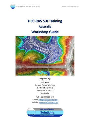
Chapter 1GRIT Manual – v. 2.0Table 1: FIRST HARMFUL EVENT FIXED-OBJECT FATALITIESBY OBJECT TYPEFIXED OBJECT20082008Tree/Shrub48%4182Utility Pole12%1029Guardrail/Longitudinal Barrier8%686Embankment6%544Highway Sign ng2%173Bridge Piers2%173Wall2%156Light Support1%125Other7%610100%8623TOTAL FATALITIESPage 1-2We Keep Virginia Moving!
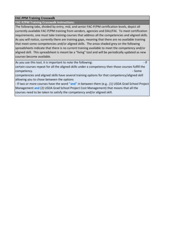
Chapter 1GRIT Manual – v. 2.0Table 2: CLEAR ZONE DISTANCES (IN FEET FROM EDGE OF DRIVING LANE)DesignSpeedDesignADT40 MPHorless45-50MPH55MPH60MPH65-70MPHFORESLOPESUnder 750750-15001500-6000Over 60006:1 orflatter7-1010-1212-1414-165:1 to4:17-1012-1414-1616-18Under 750750-15001500-6000Over 600010-1214-1616-1820-22Under 750750-15001500-6000Over 6000BACKSLOPES7-1012-1414-1616-184:1 to5:17-1012-1414-1616-186:1 820-2222-24Under 750750-15001500-6000Over 6000Under 750750-15001500-6000Over 6000*Where a site specific investigation indicates a high probability of continuing accidents, or suchoccurrences are indicated by accident history, the designer may provide clear zone distances greaterthan 30 feet as indicated. Clear zones may be limited to 30 feet for practicality and to provide aconsistent roadway template if previous experience with similar projects or designs indicatessatisfactory performance.**Since recovery is less likely on the unshielded, traversable 3:1 slopes, fixed objects should not bepresent in the vicinity of the toe of these slopes. Recovery of high speed vehicles that encroachbeyond the edge of shoulder may be expected to occur beyond the toe of slope. Determination of thewidth of the recovery area at the toe of slope should take into consideration right of way availability,environmental concerns, economic factors, safety needs, and accident histories. Also, the distancebetween the edge of the travel lane and the beginning of the 3:1 slope should influence the recoveryarea provided at the toe of slope.Page 1-3We Keep Virginia Moving!
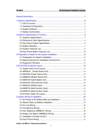
Chapter 1GRIT Manual – v. 2.0C.BARRIER WARRANTSSince guardrail itself is a hazard, it should be used only as a last resort. Consideration shouldfirst be given to alternative measures to try to avoid the need for guardrail.1. The first priority should be to eliminate the hazardous situation. Many items such astrees, boulders and jagged rock cuts can be removed, thereby eliminating the need forguardrail.2. Re-grade steep slopes and ditches, and modify drainage structures, to make themtraversable and fill in depressions.3. Relocate signs and signals supports, utility poles and endwalls by placing them,as a minimum, outside of the clear zone and preferably in an area where theycannot be easily struck.4. New structures should be designed so that headwalls, piers and abutments are outsideof the clear zone.5. Make necessary features within the clear zone of a yielding or breakaway design.Typical features that warrant consideration of barrier installation when inside theclear zone include:1. Bridge abutments, piers and parapet ends generally require shielding.2. Severe longitudinal and transverse ditches, such as ditches with front slopes steeperthan 4:1 and back slopes of 2:1 or steeper, generally warrant guardrail.3. Non-breakaway sign supports, luminaire supports and high mast lighting poles.4. Permanent bodies of water more than 2' deep.5. Fill slopes steeper than 3:1 with a height of 7' 6" or more (see Figure 1). (See RoadDesign Manual, Section A-3-Traffic Barrier Installation Criteria).6. Innocent bystander warrants such as playgrounds, schools, etc.7. Rough rock cuts and boulders are usually an engineering judgment decision.8. Retaining walls, culverts, endwalls and pipe ends are an engineering judgment basedon slopes and distance from the road.Page 1-4We Keep Virginia Moving!
Chapter 1GRIT Manual – v. 2.09. Trees with a diameter of 4" or more at maturity if they cannot be removed.10. Traffic signal supports and railroad warning devices in rural areas on high speedroadways.11. Utility poles on a case-by-case basis.Figure 1: COMPARATIVE RISK WARRANTS FOR EMBANKMENTSSHOULDERTRAVELED WAYFILL SECTION EMBANKMENTb1HEIGHTa1FILL SECTIONSLOPE (b1/a1)(RECIPROCAL)FILL SECTIONSLOPE (b1/a1)11/2:10.6BARRIER WARRANTED0.52:10.421/2:3:10.34:10.25:1BARRIER NOT WARRANTED FOR EMBANKMENT.HOWEVER, CHECK BARRIER NEED FOR OTHERROADSIDE OBSTACLES.6:10.10.0102030405060FILL SECTION HEIGHT (FT)Page 1-5We Keep Virginia Moving!
Chapter 1GRIT Manual – v. 2.0D. FLARE RATEFlare rate is the rate at which a barrier moves from a larger offset to a closer offset from theedge of traveled way as a vehicle moves downstream. For one-directional roadways, thedownstream flare rate, as the barrier moves away from the traveled way, is not restricted.Although it is desirable to flare the barrier system as far from the traveled way and as quicklyas possible, there are two criteria that must be satisfied. First, in order to keep the angle ofimpact with the barrier from being too severe, the flare rate is limited to the values shown inTable 3 which are based on speed and the stiffness of the barrier system. Second, the barriershould only be flared if it is on 10:1 or flatter slopes.Table 3: DESIGN PARAMETERS FOR ROADSIDE BARRIER
1. Cable Terminals (GR-3) . 4-1 2. Weak Post W-beam Terminals (GR-8 Type II). 4-2 3. Strong Post W-beam (GR-6, GR-7, GR-9). 4-2 4. Median Barrier Terminal (GR-9). 4