Transcription
RADIANT COOLING SYSTEMSOPPORTUNITIES FOR RADIANT COOLING IN NORTH AMERICAN CONSTRUCTIONDALE HANSCOMB, REHAU Sales Manager Building try
LEARNING OBJECTIVES OF THIS COURSEBY THE END OF THIS COURSE, PARTICIPANTS SHOULD BE ABLE TO:1. Explain the basic principles of radiant cooling systems and the factors that affect theoutput capacities2. Define the meaning of a “hybrid” HVAC system and how it can be optimized to addressthe concern of condensation3. Discuss how a hybrid HVAC system using radiant cooling leads to an improved buildingenvironment4. Describe how a hybrid HVAC system using radiant cooling can reduce initial investmentcosts5. Explain how a hybrid HVAC system using radiant cooling can reduce operating coststhrough reduced energy consumption and maintenance6. Demonstrate how a hybrid HVAC system using radiant cooling can affect the net presentvalue of the investment7. Summarize the advantages of having a radiant system from an specifier’s perspective21-Sep-15 - Page 2
PROLOGUE: RADIANT COOLING SYSTEMSCORE COMPONENTS USED IN RADIANT HEATING AND COOLING INSTALLATIONS- Crosslinked polyethylene (PEX) pipes- Distribution manifolds21-Sep-15 - Page 3
CROSSLINKED POLYETHYLENE (PEX) PIPESINTRODUCTIONHistory- Development work started in Germany in1968 for the first PEX pipes- Series production began in 1972 for PEXpipes for radiant heating applications- PEX pipes are now used for multiple fluidbased applications around the globeCapabilities of PEX pipes- Toughness to withstand jobsite conditions- High pressure and thermal capabilities- High flexibility for making tight bends- Wide range of diameters and coil lengths- Proven long life with more than 40 yearsexperience21-Sep-15 - Page 4PEXa molecule
CROSSLINKED POLYETHYLENE (PEX) PIPESAVAILABLE SIZES- Sizes 3/8, 1/2, 5/8 and 3/4 in. are mostcommonly used as radiant heating andcooling pipes* within floors, walls or ceilings- Larger sizes 1, 1 1/4, 1 1/2 and 2 in. areused to supply heated or cooled fluid todistribution manifolds and other hydroniccomponents* Note: Radiant cooling applications are mostcommonly designed with 5/8 or 3/4 in.diameters21-Sep-15 - Page 5
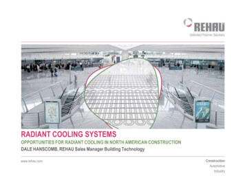
DISTRIBUTION MANIFOLDSREQUIRED IN ALL RADIANT SYSTEMS FOR CONTROL OF DISTRIBUTION PIPING- A typical circuit of radiant pipe covers 150 to 250 ft² (14 to 23 m²); typical project usesmany circuits of pipe- Circuits are connected to factory-assembled distribution manifolds to control flow- Examples:21-Sep-15 - Page 6
1. PRINCIPLES OF RADIANT COOLINGBASIC PHYSICAL PHENOMENAWhenever there is a temperature difference between two objects, both objects will attempt toequalize the temperature. The energy transfer required to approach equivalent temperaturesoccurs through radiation.Radiant energy travels from “hot” to “cold” through a space, without heating the space itself.21-Sep-15 - Page 7
PRINCIPLES OF RADIANT COOLINGBASIC PHYSICAL PHENOMENAMODES OF HEAT TRANSFER FROM OUR BODIESConduction – Direct contact- Ex: Hand on a hot plate, feet on a cool floorEvaporation – Energy transfers with the vapor associated from perspiration and breathing- Ex: Moisture lost through sweating in warm conditionsConvection – A fluid transfers the energy (air is a fluid)- Ex: Air being heated by a warm floor becomes buoyant; warm air gently rises while coldair fallsRadiation – Warm objects radiate heat waves to cooler objects in line of sight- Ex: Sun heating the earth or people warmed near a bonfire; no air is involved21-Sep-15 - Page 8
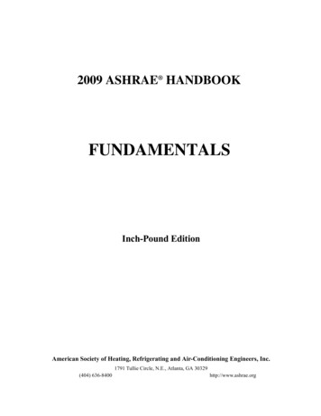
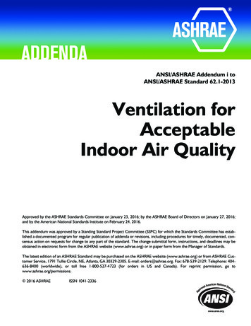
PRINCIPLES OF RADIANT COOLINGBASIC PHYSICAL PHENOMENAHUMAN COMFORT- Heat emission from the human body occursthrough four modes of transfer:- Conduction ( 5%)- Evaporation ( 20%)- Convection ( 30%)- Radiation ( 45%)- Our bodies radiate heat to any surface in line of sightwhich is cooler than our bodies’ surface temperature of85 to 90 F (29 to 32 C)- Reducing surrounding surface temperatures drawsmore heat from our bodies via radiation- Humans feel most comfortable when they can regulateat least 45% of their heat emission through radiationImage courtesy of RPA21-Sep-15 - Page 9
PRINCIPLES OF RADIANT COOLINGOVERVIEW OF RADIANT COOLING SYSTEMSHEAT TRANSFERIn a radiant heating system, warm fluid circulatesthrough PEX pipes which are integrated in the floorstructure- Heat radiates up from the warmed floor,providing a comfortable environment by warmingpeople and objects- Warm air also rises due to natural convectionFloor CoveringPEX PipeWARMED CONCRETE SLABFloor CoveringA radiant cooling system works with the reverseenergy transfer process, providing a comfortableenvironment by absorbing heat from the space- Heat transferred through the floor is removedfrom the space via the circulating fluid- In cooling mode, the same network of pipes isused as in the heating mode- In some applications pipes can be embeddedinto the ceiling or even the wall21-Sep-15 - Page 10PEX PipeCOOLED CONCRETE SLABPEX PipeCOOLED CONCRETE SLABCeiling Exposure
PRINCIPLES OF RADIANT COOLINGOVERVIEW OF RADIANT COOLING SYSTEMSINSTALLATION TYPESThermally Activated BuildingSystem (TABS)- a.k.a. TAS, BATISO, BKT- Without insulation underneath tocondition the space above andbelow- Heated/cooled floor and ceiling- Bi-directionalRadiant Floor Cooling and FloorHeating (FC/FH)- With insulation underneath tocondition the space above- Heated/cooled floor- Uni-directional21-Sep-15 - Page 11
PRINCIPLES OF RADIANT COOLINGTHERMALLY ACTIVATED BUILDING SYSTEM EXAMPLE WITH EXPOSED DUCTWORK AND CEILINGSWOODBRIDGE, ONTARIO21-Sep-15 - Page 12
PRINCIPLES OF RADIANT COOLINGTEMPERATURE SET POINTSFrom years of adjusting thermostats, we have been conditioned to believe that air temperature alonetranslates to comfort, but this is not necessarily true.We have to consider:1. Air temperatureSpace’s air temperature, monitored by thermostat as “set point temperature”2. Mean radiant temperature (MRT)Average temperature of surrounding surfaces3. Operative room temperatureWeighted average of mean radiant temperature and the conditioned space’s air temperatureThe operative temperature is what we perceive on our skin in a room and what is most important toconsider when specifying a radiant system.Higher air temperature set points during the cooling season and lower set points during the heating seasonare possible with radiant systems.21-Sep-15 - Page 13
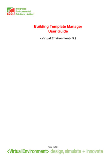
PRINCIPLES OF RADIANT COOLINGTEMPERATURE SET POINTSTHE EFFECTS OF MEAN RADIANT TEMPERATURE ON COMFORTHotPink area isthe approximatecomfort zoneColdMean Radiant Temperature ( F)MRT comfort graph originally published in Architectural Forum, January 193921-Sep-15 - Page 14
PRINCIPLES OF RADIANT COOLINGTEMPERATURE SET POINTSSpaces with 100% forced-air systems have highermean radiant temperatures due to solar gains andoffice equipment- Occupant turns down the air set point, trying tocounter radiant loads using cooler air- This requires more air movement, inefficientlycountering MRTWith an air-based system in combination with aradiant cooling system, surface temperatures arelower- This increases the heat emitted from theoccupant to surrounding surfaces via radiation- Occupant feels comfortable within the space,which removes the need for a lower airtemperature and/or increased air flow- Most efficiently counters heat loads21-Sep-15 - Page 15
PRINCIPLES OF RADIANT COOLINGRADIANT COOLING CAPACITIESTHEORYSpecific heating/cooling capacity in W/m² or Btu/(h·ft2)Heat transfer coefficientAverage surface temperatureAir temperature(q& HTC T TSURFACEAIRCoolingCeiling 1.9 Btu/(h· ft² F)Floor 1.2 Btu/(h· ft² F)Ceiling 1.1 Btu/(h· ft² F)Floor 1.9 Btu/(h· ft² F))- 60% more output from ceiling coolingsystem vs. floor cooling system- Reverse for heating modeHeatingHeat transfer coefficient (HTC) values can be approximatedbased on values from DIN EN 1264 and 1537721-Sep-15 - Page 16
FACTORS AFFECTING OUTPUT CAPACITIESRADIANT COOLING CAPACITIESPERFORMANCE OF RADIANT FLOORS AND CEILINGSFor comfort, ASHRAE Standard 55 limits floor temperature range to:- Greater than 66 F (19 C) in cooling mode- Less than 84 F (29 C) in heating modeTypical capacities based on setpoints adjusted for radiant systems:FloorTSURFACEOUTPUTHeating78-84 F19-31 Btu/(h·ft2)Cooling66-70 F8-12 Btu/(h·ft2)Heating78-84 F11-17 Btu/(h·ft2)Cooling66-70 F15-24 Btu/(h·ft2)CeilingCeilings are not limited by the ASHRAE 55floor limit; ceiling values are used only toshow capacity comparisonObtaining a designed surface temperature from a radiant floor system depends on factorssuch as average fluid temperature, pipe spacing, pipe placement, floor covering, roomset point temperature21-Sep-15 - Page 17
PRINCIPLES OF RADIANT COOLINGRADIANT COOLING CAPACITIESPERFORMANCE OF RADIANT FLOORS- Obtaining a designed surface temperature from a radiant floor system depends on factorssuch as insulation, pipe spacing, floor construction, floor covering, room set pointtemperature- Floor surface temperatures less than 66 F (19 C) should be avoided for comfort reasons,according to ASHRAE Standard 55- Under optimal design conditions, floor cooling capacities of up to 16 Btu/(hr·ft²) can beachieved*, with more typical capacities in the 8-12 Btu/(h·ft²) range*Olesen,Bjarne. Radiant Floor Cooling Systems, ASHRAE Journal, September 2008Compared with the same floor system in radiant heating mode:- Floor surface temperatures over 84 F (29 C) should be avoided for comfort reasons- Capacities of up to 32 Btu/(hr·ft²) can be achieved under optimal design conditions21-Sep-15 - Page 18
2. ADDRESSING CONCERN OF CONDENSATIONDESIGN CONSIDERATIONSHUMIDITY AND CONDENSATIONUnderstanding the basic principles of radiant systems starts to reveal where their manybenefits can be found. Many are convinced that radiant heating systems contribute tosustainable building, but still have reservations about radiant cooling.Radiant cooling needs a slightly more sophisticated design approach compared to radiantheating due to solar gains, occupant loads and resulting moisture management issues,which for most climates of North America pose concerns for specifiers.When a surface temperature is lower thanthe dew point, condensation can form21-Sep-15 - Page 19
ADDRESSING CONCERN OF CONDENSATIONDESIGN CONSIDERATIONSHUMIDITY AND CONDENSATIONCooling projects located outside aridclimates demonstrate that results are drivenby successful design, not climate- Controls are available to avoid uncomfortable anddangerous condensationSee DOE sponsored research: Radiant Cooling in US OfficeBuildings: Towards Eliminating the Perception of ClimateImposed Barriers, C.Stetiu (1998): Lawrence BerkeleyNational LaboratorySampling of radiant cooling projects in NA21-Sep-15 - Page 20Also noteworthy, usage of radiantcooling in “very cold” regions- Where specifiers have chosen radiant heating,they can easily take advantage of the coolingpotential in the existing PEX network- Addition of radiant cooling minimally increases theinitial cost and has many advantages duringoperation
ADDRESSING CONCERN OF CONDENSATIONDESIGN CONSIDERATIONSHYBRID SYSTEMSSuccessful radiant cooling projects center around understanding the correct balanceof an air handling unit (AHU) working in conjunction with a radiant system. These arereferred to as “hybrid HVAC systems.”Note: “AHU” is used to indicate any forced-air system used to condition a space (e.g., fancoil, packaged rooftop unit, DOAS).The radiant system and the AHU work together as a hybrid HVAC system, optimizingsystem design and performance by decoupling the following portions of the system:1. Hydronic and air-based2. MRT and air temperature3. Sensible (dry) and latent (humid) cooling21-Sep-15 - Page 21
ADDRESSING CONCERN OF CONDENSATIONDESIGN CONSIDERATIONSHYBRID SYSTEMSAlthough hydronic conditioning systems have many benefits, they usually can notwork alone in commercial applicationsHybrid HVAC systems must have an air-based component for several reasons:1. AHU is required to meet the building’s fresh air requirements, staying consistent withincreased building environment standards (e.g., ASHRAE 62.1, LEED)2. Downsized forced-air components must exist to counter humidity from outside air andfrom occupants within a building (latent cooling)21-Sep-15 - Page 22
ADDRESSING CONCERN OF CONDENSATIONDESIGN CONSIDERATIONSHYBRID SYSTEMSThe key to preventing condensation lies in a three specific areas:1. Infiltration- First and foremost, use a tight building envelope to reduce loads associated with nonmechanical infiltration2. Surface Temperature- Control surface temperatures by designing cooled surfaces to operate at specific supplytemperatures to prevent the surface from reaching dew point, which might lead tosurface condensation3. Relative Humidity- Control the level of humidity in a building with the AHU to keep the dew point lower thanthe cooling slab’s operating temperatures- Spaces are typically designed for about 50% maximum relative humidity during peakcooling periods21-Sep-15 - Page 23
ADDRESSING CONCERN OF CONDENSATIONDESIGN CONSIDERATIONSBUILDING CONTROL STRATEGY- Outdoor temperature sensor on thenorthern side of the building, not exposedto direct sunlight- Humidity and temperature sensor(s)in each zone to monitor dew pointsand set points- Floor temperature sensor in the upperlevel of the thermal mass- Supply and return fluid temperaturesensors in the piping network21-Sep-15 - Page 24
3. HYBRID HVAC SYSTEMS FOR IMPROVED BUILDING ENVIRONMENTTHERMAL COMFORTRadiant cooling and heating systems are integral in creating hybrid systems that reachhigher levels of thermal comfort than their 100% forced-air system counterparts.- This finding is supported in detail through a research study- Concrete Core Temperature Control Systems, 2008 by the University of Nuremberg,Germany- Study evaluates seven common and uncommon heating and cooling systems under NorthAmerican conditions for a fully simulated commercial building21-Sep-15 - Page 25
HYBRID HVAC SYSTEMS FOR IMPROVED BUILDING ENVIRONMENTCONTENT AND PURPOSE OF STUDYThe study compared several types of commercial heating/cooling systems on thefollowing attributes:- Thermal comfort (learning objective 3)- Initial investment cost (learning objective 4)- Operating costs: energy demand maintenance costs (learning objective 5)The study considers the following conditions:- North American and local building codes and standards (e.g., ASHRAE Title 24 CaliforniaStandards and Energy Code)- North American construction techniques- North American energy and investment costs including material and labor- North American climate21-Sep-15 - Page 26
HYBRID HVAC SYSTEMS FOR IMPROVED BUILDING ENVIRONMENTBASIS OF STUDY1,375Example of construction type simulated-Project type: Four-story poured commercial constructionLocation: Sacramento, CaliforniaOutside design temperatures: 100 F / 31.5 F (0.4% / 99.6%)Effective area: Approximately 14,500 ft² total area on four floorsHeaviness of construction: 160 lb/ft², cast-in-place construction21-Sep-15 - Page 27
HYBRID HVAC SYSTEMS FOR IMPROVED BUILDING ENVIRONMENTBASIS OF STUDYTHE REFERENCE OFFICE ROOMThe study focused on a typical occupied officeSupply AirReturn AirInterior loads:Office dimensions:Floor Area:Volume:- Heat loss per person: 132 W- Heating load from work wquipment: 11 W/m²- Heating load from lighting: 12 W/m²17.7 ft x 18.5 ft x 9.8 ft328 ft²3,210 ft³Lighting182.5 WPC100 WPC100 WPrinter50 WTFT42.5 WPerson132 WOccupancy:Heat emission per person:2 persons450 Btu/h (seated, office work)Electrical equipment:Lighting:3.5 Btu/(h·ft²)3.8 Btu/(h·ft²)Normal office hours:Operating hours of heatingand cooling systems:7:30 am to 6:00 pm on weekdays21-Sep-15 - Page 286:00 am to 6:00 pm on weekdaysTFT42.5 WPerson132 WLighting182.5 W
HYBRID HVAC SYSTEMS FOR IMPROVED BUILDING ENVIRONMENTCOMPARED SYSTEMS - OVERVIEW100% Forced AirSystem (AHU)Floor Radiant System(FCH) downsized AHUCeiling Radiant System(CHC) downsized AHUThermally ActivatedSlab (TAS) downsized AHUThe three hybrid HVAC systems shown above include a downsized air handling unit (AHU) todecouple and optimize the space’s cooling requirements.The University of Nuremberg’s study compares seven systems, three of which are not verycommon in North America so they are excluded from this presentation.21-Sep-15 - Page 29
HYBRID HVAC SYSTEMS FOR IMPROVED BUILDING ENVIRONMENTCOMPARED SYSTEMS - OVERVIEW100% Forced AirSystem (AHU)Floor Radiant System(FCH) downsized AHU- VAV’s positioned in corridorplenum feed the space withconditioned air- Fresh air supply requirements aremet by the air handling unit (AHU)- Supply air is conditioned to ensurerequired temperature and humidity21-Sep-15 - Page 30Ceiling Radiant System(CHC) downsized AHUZoneZoneLoads:Loads:Persons450BTU/h22personsat a450Btu/hElectrical Equipment:3.5 BTU/(hft²)3.5 Btu/h·ft²Lighting: 3.8 BTU/(hft²)Electrical Equipment:Lighting: 3.8 Btu/h·ft²External Wall:U 0.16 Btu/(h·ft²R)ExtenalWall:U 0.16BTU/(hft²R)Window:U 0.46Btu/(h·ft²R)Window:U 0.46 BTU/(hft²R)Frame:Frame:U 0.55U 0.55BTU/(hft²R)Btu/(h·ft²R)PercentageFrame: 10U 10%%Percentage Frame:Glazing:U 0.45BTU/(hft²R)Glazing:U 0.45 Btu/(h·ft²R)g 0.26g 0.26Blinds:z 0.75Blinds:z 0.75Thermally ActivatedSlab (TAS) downsized AHU
HYBRID HVAC SYSTEMS FOR IMPROVED BUILDING ENVIRONMENTCOMPARED SYSTEMS - OVERVIEW100% Forced AirSystem (AHU)Zone Loads:Floor Radiant System(FCH) downsized AHUZone Loads:22personsat 450Btu/hPersonsa ting: 3.83.8Btu/h·ft²External Wall:U 0.16Btu/(h·ft²R)ExtenalWall:U 0.16BTU/(hft²R)Window:U 0.46BTU/(hft²R)Window:U 0.46Btu/(h·ft²R)Frame:U 0.55BTU/(hft²R)Frame:U 0.55Btu/(h·ft²R)PercentageFrame:10%Percentage Frame: U 10%Glazing:U 0.45 BTU/(hft²R)Glazing:U 0.45 Btu/(h·ft²R)g 0.26g 0.26Blinds:z 0.75Blinds:21-Sep-15 - Page 31Ceiling Radiant System(CHC) downsized AHUz 0.75Thermally ActivatedSlab (TAS) downsized AHU
HYBRID HVAC SYSTEMS FOR IMPROVED BUILDING ENVIRONMENTCOMPARED SYSTEMS - OVERVIEW100% Forced AirSystem (AHU)Zone Loads:Floor Radiant System(FCH) downsized AHUZone Loads:2at 450Btu/h2 personsPersonsa 450BTU/hElectrical ft²)3.5Lighting:3.8BTU/(hft²)Lighting: 3.8Btu/h·ft²ExternalExtenalWall:Wall:U 0.16Btu/(h·ft²R)U 0.16BTU/(hft²R)Window:Window:U 0.46Btu/(h·ft²R)U 0.46BTU/(hft²R)Frame:U 0.55BTU/(hft²R)Frame:U 0.55 Btu/(h·ft²R)PercentageFrame:10%Percentage Frame: U 10%Glazing:U 0.45 BTU/(hft²R)Glazing:U 0.45 Btu/(h·ft²R)g 0.26g 0.26Blinds:z 0.75Blinds:21-Sep-15 - Page 32Ceiling Radiant System(CHC) downsized AHUz 0.75Thermally ActivatedSlab (TAS) downsized AHU
HYBRID HVAC SYSTEMS FOR IMPROVED BUILDING ENVIRONMENTCOMPARED SYSTEMS - OVERVIEW100% Forced AirSystem (AHU)Floor Radiant System(FCH) downsized AHUZone Loads:2 Persons a 450 BTU/hElectrical Equipment:3.5 BTU/(hft²)Lighting: 3.8 BTU/(hft²)21-Sep-15 - Page 33Ceiling Radiant System(CHC) downsized AHUExtenal Wall:U 0.16 BTU/(hft²R)Window:U 0.46 BTU/(hft²R)Frame:U 0.55 BTU/(hft²R)Percentage Frame: 10 %Glazing:U 0.45 BTU/(hft²R)g 0.26Blinds:z 0.75Thermally ActivatedSlab (TAS) downsized AHU
HYBRID HVAC SYSTEMS FOR IMPROVED BUILDING ENVIRONMENTTHERMAL COMFORTThermal comfort has a special standing concerning productivity in a work environment.ASHRAE Standard 55 Thermal Environmental Conditions for Human Occupancy- “Thermal comfort is that condition of mind which expresses satisfaction with the thermalenvironment.”The following factors must be considered whenthermal comfort is defined:-Clothing insulationMetabolic rateAir temperatureAir speed / draftHumidityRadiant temperature21-Sep-15 - Page 34Creates a broad range ofperceived “comfort”
HYBRID HVAC SYSTEMS FOR IMPROVED BUILDING ENVIRONMENTTHERMAL COMFORTASHRAE Standard 55 Thermal Environmental Conditions for Human OccupancyBoundaries for thermal comfort according to Standard 55- Operative temperature:- Summer period @ 50% RH:75-80 F- Winter period @ 30% RH:70-77 F66-84 F- Range of the floor temperature:- Radiant temperature asymmetry:- Warm ceiling: 9 F- Cool ceiling: 25 F- Warm wall: 41 F- Cool wall: 18 F- This is the so called comfort area, where the percentage of people who are comfortableis optimized. Less than 10% dissatisfied.21-Sep-15 - Page 35
HYBRID HVAC SYSTEMS FOR IMPROVED BUILDING ENVIRONMENTBASIS OF STUDYDESIGN TEMPERATURESThe study used:- Cooling period:- Heating period:- Minimum floor temperature:- Maximum floor temperature:21-Sep-15 - Page 3675 F68 F66 F84 F
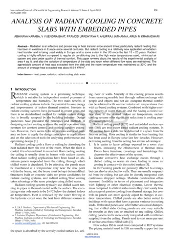
HYBRID HVAC SYSTEMS FOR IMPROVED BUILDING ENVIRONMENTRESULTS OF STUDYOPERATIVE ROOM TEMPERATURES DURING SIMULATED SUMMER WEEKIndoor operative temperature felt by office occupants during simulated week in summer100.0Operative Temperature ( 100% FORCED AIR21-Sep-15 - Page 38TUESDAYTuesdayFLOOR SYSTEM AHUWEDNESDAYWednesdayTHURSDAYThursdayCEILING SYSTEM AHU6:00 PM12:00 PM6:00 AM6:00 PM12:00 PM6:00 AM6:00 PM12:00 PM6:00 AM6:00 PM12:00 PM6:00 AM6:00 PM12:00 PM6:00 AM50.0FridayFRIDAYTAS SYSTEM AHU
HYBRID HVAC SYSTEMS FOR IMPROVED BUILDING ENVIRONMENTHEATING AND COOLING LOAD CALCULATIONHeating/cooling systems are specified and designed for “worst case scenario” withrespect to outdoor weather conditions.- What if the indoor environment is given “worst case scenario” conditions?Example: The interior loads were doubled on highest cooling load period- Assumed room was used for a meeting Wednesday afternoon from 12:00 pm to 6:00 pm- Assumed twice the occupancy and corresponding equipment loads (e.g., computers,projectors)21-Sep-15 - Page 39
HYBRID HVAC SYSTEMS FOR IMPROVED BUILDING ENVIRONMENTRESULTS OF STUDYOPERATIVE ROOM TEMPERATURES DURING SIMULATED SUMMER WEEKHybrid systems handled the doubled interior loads during Wednesday afternoon‘s meetingbetter than the 100% forced-air system100.0Operative Temperature ( 100% FORCED AIR21-Sep-15 - Page 40TUESDAYTuesdayFLOOR SYSTEM AHUWEDNESDAYWednesdayTHURSDAYThursdayCEILING SYSTEM AHU6:00 PM12:00 PM6:00 AM6:00 PM12:00 PM6:00 AM6:00 PM12:00 PM6:00 AM6:00 PM12:00 PM6:00 AM6:00 PM12:00 PM6:00 AM50.0FridayFRIDAYTAS SYSTEM AHU
HYBRID HVAC SYSTEMS FOR IMPROVED BUILDING ENVIRONMENTRESULTS OF STUDYTHERMAL COMFORT COMPARISON FOR VARIOUS METRICS100Air Quality9080Avoidance of Elevated AirSpeedFloor TemperatureRadiant TemperatureAsymmetryScaled Thermal ComfortCompliance to HumiditySetpoints706050403020Vertical TemperatureGradientsCompliance to TemperatureSetpoints21-Sep-15 - Page 41100AHUFCH AHUCHC AHUTAS AHU
4. REDUCED INVESTMENT COSTSOVERVIEWA radiant cooling system has significant benefits when used in a hybrid HVAC system toincrease economic efficiency for a building.The study compared the following cost components:- Initial investment costs- Operating costs including energy demand and maintenance (learning objective 5)- Net present value (NPV) (learning objective 6)21-Sep-15 - Page 42
REDUCED INVESTMENT COSTSRESULTS OF STUDYCOOLING LOAD CALCULATION FOR SIZING EQUIPMENT- Calculated using comprehensive DOEsoftware Energy Plus- Specific cooling load of 23.6 Btu/(h·ft²)for the office space- Air change rate of 7.5 (incl. 1.5 externalair change) was necessary for handling100% of the calculated cooling load- Radiant cooling systems cover part of thecooling load and allow for a significantreduction on the air handling side21-Sep-15 - Page 43Type ofRequired Air EquivalentHeating/Cooling Change Rate cfm for 327SystemPer Hourft2 OfficeEquivalentcfm forOfficeBuilding100% Forced Air(AHU)7.5 ACH400 cfm16,850 cfmRadiant Floor AHU5.0 ACH268 cfm11,230 cfmRadiant Ceiling AHU4.0 ACH214 cfm8,990 cfmTAS AHU4.0 ACH214 cfm8,990 cfm
REDUCED INVESTMENT COSTSRESULTS OF THE STUDYINITIAL MATERIAL INVESTMENT COSTS- Specific unit pricing for the geographic region of Sacramento, CA was considered- A survey of engineers and contractors yielded the following unit pricingUnitPriceUnitMachine LifeService andMaintenance (%)Heat generation (gas-fired boiler incl. main manifold; pipes incl. insulation, pumps, control system,exhaust system, valves)0.15 /(Btu/h)203.5Cooling production (piston water set, recooling plant, pipes incl. insulation, control system, pumps,valves)0.38 /(Btu/h)153AHU as mixed air system incl. AC device with four thermodynamic air treatment functions, ductsystem with insulation, outlets, built-in parts such as fire protection valves etc., control system0.8 /(ft³/h)153.55 /ft²301Sub-distribution FH/FC incl. control system, pipes incl. insulation, pumps, sub-distribution manifold,valves4.5 /ft²201.5Concrete core temperature control incl. connection3.5 /ft²301Sub-distribution concrete core temperature control incl. control system, pipes incl. insulation, pumps,sub-distribution manifolds, valves5.5 /ft²201.5Chilled ceiling incl. connection25 /ft²201.5Sub-distribution chilled ceiling incl. control system, pipes incl. insulation, pumps, sub-distributionmanifolds, valves5 /ft²201.5ComponentUnder floor heating / under floor cooling incl. connection21-Sep-15 - Page 44
REDUCED INVESTMENT COSTSRESULTS OF STUDYINITIAL INVESTMENT COST COMPARISON100PEX pipes, manifolds,valves, pumps, sensors,control units, etc.Radiant SystemCeiling panels,connections, insulation,installation, etc.AHUAll air equipment, ducting,controls, humidificationCooling ProductionChilled fluid generation,control unit, connectionsScaled Initial Investment CostRadiant Sub-distribution90-21%80-29%-31%70605040302010Heat ProductionBoiler, pumps, controlunit, valves, etc,21-Sep-15 - Page 450AHUFCH AHUCHC AHUTAS AHU
5. REDUCED OPERATING COSTSOVERVIEWHybrid HVAC systems incorporating a radiant system can aid in reducing energyconsumption- The study compared the following categories of energy demand:- Heat generation- Cooling production- Auxiliary air handling components (i.e., fans for air distribution)- Auxiliary radiant components (i.e., circulator pumps for fluid distribution)21-Sep-15 - Page 46
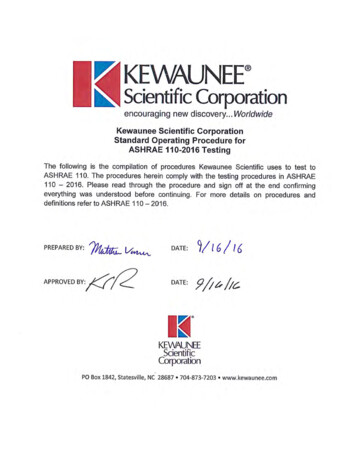
REDUCED OPERATING COSTSRESULTS OF STUDYFINAL ENERGY DEMAND COMPARISON60,000Auxiliary Radiant incl.DistributionAuxiliary AHU incl.DistributionCooling Production forRadiantCooling Production forAHUAnnual Energy Demand Btu/ft250,000-30%40,000-38%30,00020,000Heat Production forRadiant10,000Heat Production forAHU0100% AHUFHC AHUCHC AHUFinal energy demand correlates directly with building owner’s operating costs21-Sep-15 - Page 47-40%TAS AHU
REDUCED OPERATING COSTSRESULTS OF STUDYMAINTENANCE COST COMPARISON3.00Pumps, miscellaneousRadiant SystemMiscellaneous servicingAHUFilter replacement, blowerfan motors, miscellaneousservicingCooling ProductionPumps, chillermaintenanceHeat ProductionPumps, boilermaintenance21-Sep-15 - Page 49Annual Maintenance Costs ( /sq ft)Radiant 00100% AHUFCH AHUCHC AHUTAS AHU
6. NET PRESENT VALUE CALCULATIONOVERVIEWThe net present value (NPV) is defined as the total present value (PV) of a timeseries of cash flows.- Present value is the value on a given date of a future payment or series of futurepayments, discounted to reflect the time value of money and other factors such asinvestment riskThe comparison was made with the following assumptions:- The rate of interest is calculated to be 3.8%- The price increases for natural gas and for electricity are set to 4% annually- The term of investment is 15 years, the estimated life of major components of theAHU system21-Sep-15 - Page 50
NET PRESENT VALUE CALCULATIONRESULTS OF STUDYNET PRESENT VALUE WITH CONVENTIONAL ENERGY SUPPLY150140100% AHUSee legend onleft for eachsystem’s savingsat year 15130FCH AHU-30%CHC AHU-27%TAS AHU-35%NPV ( /sq ft)1201101009080706050012345678Years9101112131415- High-cost components of an AHU are estimated to need major servicing after year 15- This indicates that a system running for longer periods of time (e.g., 30 years) would illustratehuge advantages for the hybrid radiant systems if the NPV were extended to look at a building’slife time21-Sep-15 - Page 51
7. ADVANTAGES TO SPECIFIERSOVERVIEWThe study compared the following parameters for the four systems:1. Thermal comfort2. Initial costs3. Energy demand4. Maintenance costsThe comparison lead to an overall score based on the following weighted values:CategoryWeighted AverageThermal comfort30%Initial costs20%Energy demand40%Maintenance costs10%Total:100%21-Sep-15 - Page 52
ADVANTAGES TO SPECIFIERSRESULTS OF STUDYOVERALL EVALUATIONSystems scored on four main parameters100Energy Demand80Evaluation %Maintenance Costs60Intial Costs40Thermal Comfort200100% ForcedAir21-Sep-15 - Page 53FCH AHUCHC AHUTAS AHU
ADVANTAGES TO SPECIFIERSFROM EXPERIENCEThe study and also the experience from hundreds of radiant cooling projects realizedthroughout the world prove the advantages of these systems.Increased Thermal Comfort- Radiant cooling optimizes the surface temperatures of the occupants’ surroundings,providing a comfortable environment- The human body feels most comfortable when it can regulate at least 45% of its heatemission via radiation achieved through a radiant system- Comfortable cooling is provided with reduced ventilation air and little to no flow noises21-Sep-15 - Page 54
ADVANTAGES TO SPECIFIERSFROM EXPERIENCEThe study and also the experience from hundreds of radiant cooling projects realizedthroughout the world prove the advantages of these systems.Reduced Investment Costs- Radiant cooling can lead to a significant investment reduction in forced-air systemcomponents and ductwork- Radiant cooling systems have lower operating costs due to the superior heat transferproperties of water compared to air- A 1 in. water pipe carries same thermal energy as 10 in. x 18 in. rectangular duct- A 60 watt circulator can de
- Under optimal design conditions, floor cooling capacities of up to 16 Btu/(hr ·ft²) can be achieved*, with more typical capacities in the 8-12 Btu/(h ·ft²) range *Olesen, Bjarne. Radiant Floor Cooling Systems, ASHRAE Journal, September 2008 Compared with the same floor system in radiant heating mode: