Transcription
International Journal of Scientific & Engineering Research Volume 9, Issue 4, April-2018ISSN 2229-5518238ANALYSIS OF RADIANT COOLING IN CONCRETESLABS WITH EMBEDDED PIPESABHINAVA KARABA, V VIJENDRA BHAT, PRAMOD UPADHYAYA R, ANUPRAJ JATHANNA, ARUN M KRAMADHARIAbstract— Radiation is an effective and proven way of heat transfer since ancient times; particularly radiant heating thathas been in existence in Europe since several centuries. But radiant cooling is a relatively new application of radiationheat transfer and is being used widely in Europe and to some extent in the US since the last 15 – 20 years. Radiantcooling is highly efficient compared to regular air conditioning due to the high water temperatures used, minimized airsystem and also better quality of thermal comfort. This paper reviews about the results of the experimental analysis ofarea 4 sq. ft. and also the variation of temperature of the slab and room when different flow rates are maintained. Theappreciable amount of heat was extracted from the slab and the room temperature was maintained at 32 C and the2amount of average heat extracted was about 0.5-1 kW/m .Index terms— Heat, power, radiation, radiant cooling, slab, water.—————————— ——————————1 INTRODUCTIONRADIANT cooling system is a promising technique,which is suitable for independent control processes oftemperature and humidity. The two main benefits ofradiant cooling systems include the potential to save energyand improvement of indoor thermal comfort. Interests inradiant cooling systems have increased in recent years andthere is no standardized method for radiant system designthat is broadly accepted by the building industry. Designguidelines have provided the principles and methods ofdesigning radiant cooling systems, the use of operative temperature for comfort control, and cooling capacity estimation. However, there seems to be no obvious source of guidance on how to apply the design principles to applicationsand on the selection of tools for analyzing performance andoptimizing design. [1].Radiant cooling cools a floor or ceiling by absorbing theheat radiated from the rest of the room. When the floor iscooled, it is often referred to as radiant floor cooling; coolingthe ceiling is usually done in homes with radiant panels.Most radiant cooling applications have been based on aluminum panels suspended from the ceiling, through whichchilled water is circulated. To be effective, the panels mustbe maintained at a temperature very near the dew pointwithin the house, and the house must be kept dehumidified.Structures built on concrete slabs are prime candidates forradiant cooling systems, and radiant ceiling/floor coolingtakes advantage of the same principle using chilled water.Radiant cooling systems typically use chilled water running in pipes in thermal contact with the surface. The circulating water only needs to be 2-4 C below the desired indoorair temperature. Heat is removed by the water flowing inthe hydronic circuit once the heat from different sources ining, floor or walls. Majority of the cooling process resultsfrom removing sensible heat through radiant exchange withpeople and objects and not air, occupant thermal comfortcan be achieved with warmer interior air temperatures thanwith air based cooling systems. Combined with higher cooling capacity of water than air, and the having a cooled surface close to the desired indoor air temperature, radiantcooling systems offer significant reductions in cooling energy consumption [2].Radiant ceiling panel (RCP) and embedded surface system (ESS) are two water based radiant cooling systems. InESS cooling from a slab can be delivered to a space from thefloor or ceiling. Floor cooling is similar to floor heating thathas been used in Europe since last few decades. However,delivering cooling from the ceiling has several advantages:1. It is easier to leave ceilings exposed to a room thanfloors, increasing the effectiveness of thermal mass.Floors have furniture, coverings and furnishings thatdecrease the effectiveness of the system.2. Greater convective heat exchange occurs through achilled ceiling as warm air rises, leading to more aircoming in contact with the cooled surface [3].In RCP cooling panels are generally attached to ceilings,but can also be attached to walls. They are usually suspended from the ceiling, but can also be directly integrated withcontinuous dropped ceilings. Modular construction offersincreased flexibility in terms of placement and integrationwith lighting or other electrical systems. Lower thermalmass compared to chilled slabs means they can’t easily takeadvantage of passive cooling from thermal storage, but controls in panels can more quickly adjust to changes in outdoor temperature. Chilled panels are also better suited tobuildings with spaces that have a greater variance in coolingloads. Perforated panels also offer better acoustical dampening than chilled slabs. Ceiling panels are also very suitablefor retrofits as they can be attached to any ceiling. Chilledceiling panels can be more easily integrated with ventilationsupplied from the ceiling. Panels tend to cost more per unitof surface area than chilled slabs [3].Now a days ESS is used more compared to RCP systems.The piping material used in ESS are usually copper but —— 1,,3,4,5 Students, Department of Mechanical Engineering, ShriMadhwa Vadiraja Institute of Technology and Management, Bantakal,Udupi- 574114, India. 2 Assistant Professor, Department of Mechanical Engineering, ShriMadhwa Vadiraja Institute of Technology and Management, Bantakal,Udupi- 574114, India. navabhi.marali@gmail.com, 91 9483927493the space is absorbed by the actively cooled surface i.e., ceil-IJSER 2018http://www.ijser.org
International Journal of Scientific & Engineering Research Volume 9, Issue 4, April-2018ISSN 2229-5518to its high cost and difficulty in embedding it inside concrete, it has been replaced by the cross linked polythene(PEx) as it is cheaper and durable compared to copper piping [4].2 LITERATURE REVIEWSeveral authors discuss thermal comfort in spaces with aradiant cooling ceiling. A few papers published in conference proceedings and scientific journals describe computermodelling of the system with cooling ceiling. Some of thepublished papers are,Takehito Imanari along with Toshiaki Omori andKazuaki Bogaki described an experimental investigation ofthermal comfort and the numerical simulation of energyconsumption in 1999. The purpose of this study was to investigate various characteristics of radiant ceiling panel system and its applications [5].Fariba Alamdari (1998) presents the room air distribution and thermal environment of combined displacementventilation and cooled ceiling systems. A field flow modelbased on computational fluid dynamics (CFD) was used tosimulate comparative environmental performance of displacement ventilation with and without cooling ceiling [6].Guruprakash Shastry, Senior manager – Green Initiatives, Infosys reviews the radiant cooling system present in abuilding at Hyderabad Infosys Campus and states that theradiant cooling system consumed 33% less energy whencompared to the conventional air-conditioning system forthe period April 2011 - March 2012. The building has a totalbuilt-up area of about 24000 sq. m. distributed into east andwest wings of 11600 sq. m. each and a central wing of about800 sq. m. About 85% of the total building area is airconditioned office area and the total occupancy of the building is about 2500. The most significant feature of the building is that it is split into two symmetric halves. One half iscooled by conventional (but very efficient) air conditioningand the other half by radiant cooling [7].Bjarne W. Olesen reviews that for well-designed buildings these types of system are capable of providing a comfortable indoor climate both in summer and in winter in different climatic zones. Various control concepts and corresponding energy performance are presented. To removelatent heat, these systems may be combined with an air system. This air system can, however, be scaled down with thebenefit of improved comfort (noise, draught) compared tofull air-conditioning. An added benefit can be added by reducing building height. Finally, surface heating and coolingsystems use water at a temperature close to room temperature. This increases the possibility of using renewable energy sources [8].Lin Su et al., reviews that Concrete ceiling panel coolingsystem had advantages of comfort and energy saving. Thisstudy presented heat transfer and cooling characteristics ofthe concrete ceiling radiant cooling panel. Two dimensionalmathematical model of steady state heat transfer was developed by using finite difference method. Heat transfer in theconcrete panel was numerically simulated. Temperatures ofinterior and surface of the concrete panel were obtained.According to calculated results, temperature distribution ofthe concrete panel was analyzed under the condition of different supply water temperatures and distances of tubes,and the numerical model was accurate enough by the exper-239iment. Actual operation characteristics of concrete ceilingpanel cooling system were analyzed according to measureddata. The cooling capacity of the concrete panel was influenced by supply water temperature, distance of tubes andwater flow rate [9].Zhen Tian and James A. Love described that through integrated field measurements and building simulation withEnergy Plus, it was found that the building energy performance could be improved by reducing conflicts betweensystems, especially simultaneous heating and cooling. Control strategies to coordinate air and radiant system operationare crucial to improve the overall building energy performance. Use of “low quality” cooling sources with radiantslab cooling was also considered [10].Tomas Mikeska carried out theoretical investigationswith a CFD model of the test room. The aim of the development of the CFD model was to allow for a deeper understanding of the diffuse ceiling inlet and wall radiant systemand to facilitate efficient and economical optimization of thedesign taking into account various parameters. The resultsof the investigations presented show that a diffuse ceilinginlet can successfully ventilate and cool the room with ahigh density of occupants using supply air at an averagetemperature of 21 C. The resulting cooling power was 23W/m2 at a flow rate of 5.8 l/s·m2 of floor area. The averageair temperature in the test room was 24.5 C. The coolingpower of 32 W/m2 was available at a flow rate of 8.0 l/s·m2of floor area, which resulted in an average air temperature inthe test room of 24 C. This creates a comfortable indoor environment without draughts. Sufficient mixing was obtainedmainly as a result of the interaction of incoming air and heatsources situated in the test room. The diffuse ceiling inletcan therefore be considered a well-performing alternative tothe traditional means of mechanical ventilation in spaceswith a high density of occupants. The results also show thatplastic capillary tubes integrated in a layer of high performance concrete can provide the energy needed for coolingbetween 29 W/m2 and 59 W/m2 of floor area with coolingwater temperatures between 22 C and 18 C. This resulted inindoor air temperatures of 24.5 C and 22 C, respectively,and a draught-free indoor environment. The relatively highreaction speed of the designed system of radiant cooling wasachieved as a result of the slim construction of high performance concrete. Measured values were used to validate adeveloped CFD model, with the aim of achieving a preciseCFD model which can be used to evaluate indoor comfortnumerically. The results show that transient calculationsusing Large Eddy Simulation turbulent models can give agood prediction of temperatures and air flow velocity magnitude in a room ventilated using a diffuse ceiling inlet.However, steady-state turbulent models needed to be applied to obtain adequate predictions in the rooms equippedwith a wall radiant cooling system [11].IJSER3 EXPERIMENTAL SETUPThe experimental setup or model is based on the typicalbuilding. The slab of 4 sq. ft. area was pre-casted and thenwas placed on the room of 3 sq. ft. area with the wall thickness of 150mm. A window of area 150 x 150 mm2 and a ventilation of area 200 x 70 mm2 was provided for the room forcontinuous circulation of air inside the room.Another slab was pre-casted along with the copper tub-IJSER 2018http://www.ijser.org
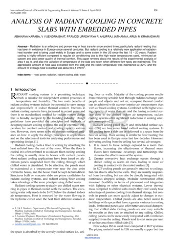
International Journal of Scientific & Engineering Research Volume 9, Issue 4, April-2018ISSN 2229-5518ing of 3mm diameter embedded in it. This slab placed abovethe room. A 12.5 mm thick hollow box was prepared fromGalvanized Iron sheets and inlet and outlet provisions forcirculation of water was given in it. Also a solar water heatermodel was prepared of size 4 sq. ft. for further heating ofwater with a black glass on top of it.The slab with copper tubing was placed on top of theroom and then the box of GI sheet was placed on top of it.Also the arrangement for further heating of water wasplaced on top of the GI sheet box with an insulating layer inbetween them. The piping for inlet and outlet of water andthe temperature sensors were placed at inlet to slab, inlet toGI sheet, outlet from slab, outlet from GI sheet, inside theroom. Figure 1 shows the schematic block diagram of thesetup. Figure 2 shows the slab with the copper tube embedded in it.Fig. 2. Piping inside the slab4 METHODOLOGYThe water is made to flow through the piping and thenflow rate (ṁ₁ and ṁ₂) was measured separately at the outletfrom slab and outlet from the GI sheet. Also the temperaturewas noted down at different inlets and outlets (T₁, T₂ andT₃). The water from both the outlets was then combined andsupplied to the top most layer for further heating of waterfrom solar radiation. From the obtained readings theamount of heat extracted from the slab (Q) is calculated using the Heat and Mass transfer formulae.IJSER1.Fig. 1. Block diagram of the experimental setupTable 1: List of components240Heat extracted from the slab with respect to embeddedtubes,Watt . (1)Where,Q₁ Heat extracted from the slab with respect to embeddedtubes (W)ṁ₁ Mass flow rate of water through the embedded tubes(kg/s)CP Specific heat of water at avg. temp of T₁ and T₂ (J/kgK)T₂ Outlet temperature of water from the tubing (K)T₁ Inlet temperature of water in to the tubing (K)2.Heat extracted from slab by GI sheet box,Watt (2)3.1 WorkingThe water is supplied to the copper piping inside the slaband the GI sheet box simultaneously. Once the water starts flowing through the piping and the box it starts absorbing heat fromthe slab through conduction from both inner (piping) and outer(box) layers, thus reducing the temperature of the slab. Thus theroom gives away the extra heat to the chilled slab by means ofconvection which in turn results in the temperature drop insidethe room. The heated water from both piping and the box is thensent to the top most layer for further heating by solar radiation.This hot water can be then utilized for the domestic as well aspower generation.Where,Q₂ Heat extracted from the slab by GI sheet box (W)ṁ₂ Mass flow rate of water through the GI sheet box (kg/s)CP Specific heat of water at avg. temp of T₁ and T₃ (J/kgK)T₃ Outlet temperature of water from the tubing (K)T₁ Inlet temperature of water in to the tubing (K)3.Total amount of heat extracted from the slab,Qₐ [(Q₁ Q₂)/ Area of the slab] W/m2 . (3)5 EXPERIMENTAL RESULTSExperiment was carried out on the setup and resultswere obtained for four different cases. In all the four casesvariation of the room temperature with respect to time wasobserved and noted. Also the heat extraction from the slaband by the solar radiation was calculated. This heat extraction from the slab also resulted in the reduction of roomtemperature. The results of the various cases are,IJSER 2018http://www.ijser.org
International Journal of Scientific & Engineering Research Volume 9, Issue 4, April-2018ISSN 2229-5518CASE 1: Slab without any flow of water.In this case there was no flow of water inside the embedded tubes and the slab is kept open to the direct solarradiation. It is the same condition as that of the normalbuilding. Here the room temperature will be almost equal tothat of ambient temperature because there is no cooling process taking place. Also the slab temperatures will be highand they will radiate the heat absorbed from the sun into theroom. Table 2 shows the temperature readings in case 1.241kW/m2. This was due to the presence of the GI box. TheTable 4 and Table 5 show various readings of case 3.Table 4: Temperature readings of case 3.Table 2: Readings of Case 1.Table 5: Heat extracted in case 3.All the cases was studied with an average watertemperature of 32 C. Each case was studied from 9.00AM to4.30PM.CASE 2: Slab with flow of water.In Case2 water was passed only through embeddedpipes and the temperature distribution was noted down.The room temperatures decreased as a result of heat extraction from the slab. The heat inside the room was then absorbed by the chilled slab. Here the cooling effect can beincreased by decreasing the inlet water temperature. Table 3shows that the room temperature can be maintained by varying the temperature of water as well as the flowrate of water. Average heat extracted was 0.131 kW/m2. The roomtemperature was maintained at an average of 32 C.IJSERTable3: Readings and heat extracted in Case 2.CASE 3: Slab with water flow in addition with water flowinside GI box.In case 3 along with embedded tubes, a GI box is placeddirectly above the slab and water is passed through it. ThisGI box extracts heat from the upper layer of the slab andalso partially insulates the solar radiation falling on the slab.On the day of experimentation, the weather was slightlyforecast. So the water temperature exiting the GI box waslow and since there was lesser air movement in the atmosphere, the room temperature was slightly more than expected. If the air movement is good then the temperature ofthe room will reduce since some amount of heat is carriedaway by the air. The average heat extracted was 0.59CASE 4: Slab with water flow along with water flowthrough GI box and solar water heater with insulation inbetween.Compared to all the previous cases this one is the bestsuited case for cooling the room. The slab here is completelyinsulated from the solar radiation because of two layers present above the slab. Also there is an insulating layer betweenthe solar water heater and GI box. The only heat entering theroom will be through the walls and via air flow taking placebetween the room and environment. In order to cool theroom the water temperature must be lower than that of ambient temperature.The heat extraction here will be more since solar waterheater is used in this case. The heat obtained in this case is atan average of 1 kW/m2. Table 6 and Table 7shows differentreadings of case 4 and also imply that room temperature hasnotably lower compared to other cases. Also the water getsheated from solar radiation along with the heat extractionfrom the slab. Maximum temperature of water that can beobtained from the solar radiation is about 60 C (by using flatplate collector). This temperature can be furthermore increased up to 90 C by using parabolic mirrors or using blacktubes. The temperature obtained can be utilized for domesticpurposes as well as power generation.Table 6: Temperature readings of case 4.Table 7: Heat extracted in case 4.IJSER 2018http://www.ijser.org
International Journal of Scientific & Engineering Research Volume 9, Issue 4, April-2018ISSN 2229-5518242CFD simulations can be performed to validate the test results and optimization of the flow parameters, the fluidproperties can be performed to improve the performance ofthe radiant cooling systems [12].REFERENCES[1]5.1 GRAPHSASHRAE Handbook. HVAC systems and equipment. Chapter 6. Panelheating and Cooling design.[2] es- radiant-coolingwork/[3] of- radiant-coolingsystems/[4] Radiant cooling Design Manual, First Edition (2013), published by Uponor,Inc.[5] Imanari, T., Omori, T., Bogaki, K., Thermal comfort and energy consumption of the radiant ceiling panel system. Comparison with the conventionalall-air system, Energy and Buildings 30, pp 167 – 175, 1999.[6] Alamdari, F., Displacement ventilation and cooling ceilings, Proceedings ofRoom vent ‘98, pp. 197-204, Stockholm 1998.[7] Guruprakash Sastry, First radiant cooled commercial building in India –critical analysis of energy, comfort and cost.[8] Bjarne W Olesen, Radiant Heating and Cooling by Embedded water basedSystems, Technical University of Denmark, 2008[9] Lin Su, Nianping Li, Xuhan Zhang, Yeyao Sun, Jiawei Qian (2015) Heattransfer and cooling characteristics of concrete ceiling radiant cooling panel.[10] Zhen Tian, James A. Love, An integrated study of radiant slab coolingsystems through experiment and building simulation, Ninth InternationalIBPSA Conference Montreal, Canada ,August 15-18, 2005.[11] Tomas Mikeska, Energy performance of ventilation, heating and coolingsystems integrated in sandwich panel of high performance concrete.[12] S. M. Masutani and P. K. Takahashi, Ocean Thermal Energy Conversion(OTEC).IJSERFig. 3. Variation of Room Temperature Vs Time.Figure 3 shows the variation of room temperature withtime. From the graph it is noted that case 4 is most efficientcompared to all cases. Also comparison of case 3 and case 2cannot be done due to changes in weather but can be concluded that those two cases yield almost same results withhigher heat extraction in case 3. The graph also implies thatwithout any setup for cooling (case 1) the room temperatureis same as that of the ambient temperature. This comparisontells that the room cooling has been done in all other cases.6CONCLUSIONVarious experiments have been conducted using the radiant cooling technique using embedded copper tubes in theconcrete slab. It has been noticed that there the water circulated in the embedded tubes had an increase of temperatureof 2-5 C during the test. This increase in temperature leadsto extraction of an average of 0.5-1kW/m2 out of the concrete slab which would have otherwise caused in the increase of the room temperature. During the test the roomtemperature was constant at an average temperature of 32 Cand the slab temperature was maintained at 34 C. This is aconfirmation of the radiant cooling. The effectiveness of theradiant cooling system can be increased by using sub-cooledwater.The hot water obtained from the top layer can be usedfor domestic purposes if the surface area for heating issmaller i.e. in houses. If the surface area is large enough sayindustries then one can go for power generation. The currentwork can be extended to generate power to improve theoverall performance of the radiant cooling system. FurtherIJSER 2018http://www.ijser.org
tem (ESS) are two water based radiant cooling systems. In ESS cooling from a slab can be delivered to a space from the floor or ceiling. Floor cooling is similar to floor heating that has been used in Europe since last few decades. However, delivering cooling from the ceiling has several advantages: 1.