Transcription
Building Template ManagerUser Guide Virtual Environment 5.9Page 1 of 24
Contents1.2.Introduction.3Building Template Manager Window .42.1.Project Template File .42.2.Template Types.52.3.Import Templates .52.3.1.Copy To Project.62.3.2.Browse Template Databases .72.4.Add Template .72.5.Remove Template .72.6.Save .72.7.OK .72.8.Cancel .73.Template Types.83.1.Room Attributes.83.1.1.Lettable Floor Area .83.1.2.Circulation Floor Area.83.2.Constructions .83.2.1.Opaque .93.2.2.Glazed .93.2.3.Apache Constructions Database.93.3.MacroFlo Opening Types .103.4.Thermal Conditions .103.4.1.Building Regulations.103.4.2.Room Conditions .113.4.3.System.123.4.4.Casual Gains. .143.4.5.Air Exchanges .173.4.6.Apache Profiles Database .193.5.Electric Lighting .203.5.1.Lighting General .203.5.2.Lighting Luminaires .213.6.Radiance Surface Properties .223.6.1.Opaque .223.6.2.Glazed .223.6.3.Radiance Surfaces Database.22Page 2 of 24
1. IntroductionThe Building Template Manager (BTM) is the room template manager for the VE programs. It allows for easy designation of common zone features andconditions when constructing a VE model.Page 3 of 24
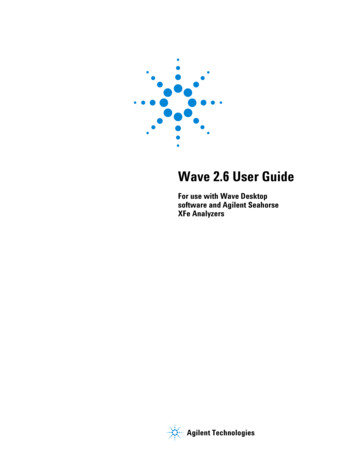
2. Building Template Manager WindowThe Building Template Manager window can be opened by selecting Templates Building Template Manager from the VE menus. The following window willthen be displayed:2.1. Project Template FileFor each modelling project, a project specific template file is created with theextension *.mtd. This holds the template(s) used by the modelling project.Page 4 of 24
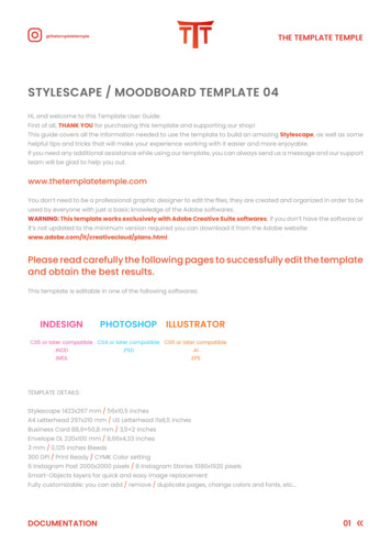
2.2. Template TypesThere are 6 template types and these are: Room Attributes – data relating to lettable area.Constructions – thermophysical properties of building elements.MacroFlo Opening Types – air flow characteristics of doors, windowsand ventilation louvres.Thermal Conditions – room heating and cooling plant, casual gains andventilation.Electric Lighting – electric lighting properties.Radiance Surface Properties – default properties/colours for radiancesurfaces.The template types are explained in more detail later in the user guide.2.3. Import TemplatesThis button produces the following window which allows the user to browse thetemplate database:Page 5 of 24
There are currently four template database files: CommercialDomesticEducationalMedicalWhen a database file is opened, the following window will appear:Note the window which appears is dependent on the template type currentlyselected. Therefore if it is a room attributes template which the user is afterthen the user must first select the Room Attributes template type. This appliesto all template types.2.3.1. Copy To ProjectUse this button to copy the selected template to the project.Page 6 of 24
2.3.2. Browse Template DatabasesPress this button to begin browsing the template databases again.2.4. Add TemplateThis button adds a template to the project model template type currently active.It is then available for editing.2.5. Remove TemplateThis button removes a template from the project model template type currentlyactive.2.6. SaveClick the save button to save any changes made in the BTM.2.7. OKClick the OK button to exit the BTM once changes have been made andsaved.2.8. CancelClick the cancel button to exit from the BTM without saving any changes.Page 7 of 24
3. Template TypesThe Building Template Manager is split up into 6 template types: Room AttributesConstructionsMacroFlo Opening TypesThermal ConditionsElectric LightingRadiance Surface PropertiesEach is described in detail below.3.1. Room AttributesThis contains data relating to lettable area.3.1.1. Lettable Floor AreaThis is the percentage of the floor area that is lettable.3.1.2. Circulation Floor AreaThis is the percentage of the floor area that is classed as circulation.3.2. ConstructionsThis section is where the opaque and glazed constructions are specified fortemplates.Page 8 of 24
3.2.1. OpaqueThis section contains drop down lists for the following which are used to select thedesired construction: RoofCeilingExternal WallInternal PartitionGround FloorDoor3.2.2. GlazedThis section contains drop down lists for the following which are used to select thedesired construction: RooflightExternal GlazingInternal Glazing3.2.3. Apache Constructions DatabasePressing this button opens up APcdb to allow for creation/removal/editing ofconstructions. See the APcdb User Guide.Page 9 of 24
3.3. MacroFlo Opening TypesThis section is where the MacroFlo opening types are assigned to templates.The opening types available are: RooflightExternal GlazingInternal GlazingDoor3.4. Thermal ConditionsThis section is where room thermal conditions are assigned to templates.There are four tabs for thermal conditions data: HeatingCoolingCasual GainsAir Exchanges3.4.1. Building RegulationsThis tab allows the template to be associated with an NCM activity template forBuilding Regulations compliance. See the Building Regulations user guides for moreinformation.Page 10 of 24
3.4.2. Room ConditionsThis tab contains controls for setting default room heating attribute data.3.4.2.1. Heating ProfileThis user can set the percentage profile group that defines the operation of the heatingsystem.Note that for heating to operate, the percentage profile must exceed 50%.In most cases, prior to creating a template, the user should define profiles using APpro.These profiles will then appear in this and any other Percentage Profile Group dialoguebox.3.4.2.2. Simulation Heating SetpointThis is the setpoint for heating control. This value must be less than or equal to theSimulation Cooling Setpoint at all times. The heating setpoint can be constant or it canfollow a timed profile which can be defined using APpro.3.4.2.3. Heating ZoneThis allows you to set a default heating zone to which spaces will be assigned for thepurposes of thermal calculations.3.4.2.4. Cooling ProfileHere you can set the percentage profile group that defines the operation of the coolingsystem.Note that for cooling to operate, the percentage profile must exceed 50%.Page 11 of 24
In most cases, prior to creating a template, the user should define profiles using APpro.These profiles will then appear in this and any other Percentage Profile Group dialoguebox.3.4.2.5. Simulation Cooling SetpointThis is the setpoint for cooling control. This value must be greater than or equal to theSimulation Heating Setpoint at all times. The cooling setpoint can be constant or it canfollow a timed profile which can be defined using APpro.3.4.2.6. Cooling ZoneThis allows you to set a default cooling zone to which spaces will be assigned for thepurposes of thermal calculations.3.4.2.7. Solar Reflected FractionThis is the fraction of solar radiation which, once transmitted by the glazing room, is then rereflected out of the window. The value of solar fraction lost depends primarily on internalsurface emissivity and room geometry. As a general rule, windows which have a high roomview factor will have higher solar re-reflected fractions. For ApacheCalc only.3.4.2.8. Furniture Mass FactorIn ApacheSim the thermal mass of the air in a room is calculated as the product of the roomvolume, the air density and the air specific heat capacity at the room conditions. See theApache User Guide for more information.3.4.3. SystemPage 12 of 24
This tab contains controls for setting default room cooling attribute data3.4.3.1. HVAC SystemThis is where the system that controls the room and supply air condition (set in ApacheSystems) is chosen for the current template. This choice dictates the efficiency and primaryenergy use of the system chosen for heating, cooling, air supply, extraction and anyauxiliary mechanical ventilation.3.4.3.2. Auxiliary SystemThis is where the system that controls the supply air condition for any auxiliary ventilation(set in Apache Systems) is chosen for the current template. This choice dictates theefficiency and primary energy use of the system chosen for heating, cooling, supplying andextracting the auxiliary system air.3.4.3.3. DHW SystemThis is where the system that controls the domestic hot water (set in Apache Systems) ischosen for the current template. This choice dictates the efficiency and primary energy useof the system chosen for heating.3.4.3.4. Heating Plant Radiant FractionThis is the fraction of radiant heat given out by the heat emitter, e.g. 0.0 for forced warm airheaters and 0.9 for high temperature radiant heaters.3.4.3.5. Simulation Heating Unit CapacityThis is used in dynamic thermal simulation only and the user can choose either unlimitedplant capacity or can set a limit.3.4.3.6. Cooling Plant Radiant FractionThe Cooling Device Radiant Fraction is the cooling that is seen as radiant energy, e.g. 0.0for an air system.3.4.3.7. Simulation Cooling Unit CapacityThis is used in dynamic thermal simulation only and the user can choose either unlimitedplant capacity or can set a limit.3.4.3.8. Minimum Percentage SaturationThis is the minimum saturation to be maintained during the hours of plant operation. If thepercentage saturation in the space falls below the value entered here during the time ofplant operation, humidification will occur to meet this set-point.3.4.3.9. Maximum Percentage SaturationThis is the maximum saturation to be maintained during the hours of plant operation. If thepercentage saturation in the space rises above the value entered here during the time ofplant operation, dehumidification will occur to meet this set-point.Page 13 of 24
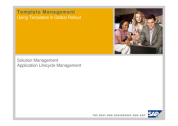
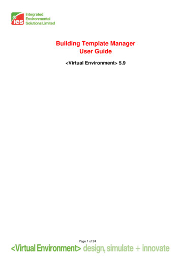
3.4.3.10. System Outside Air Supply Minimum Flow RateThe supply air condition is set in the Apache Systems dialog. It is the air supply that will betempered by the system plant and the results will be seen separately form the room load.3.4.3.11. System Air Supply Variation ProfileThis is the variation profile that will be applied to the system air supply. The modulatingprofile can be set in APpro.3.4.3.12. Additional Free Cooling Flow CapacityThis indicates the maximum intake of outside air that is available for free cooling. In thecase of a naturally ventilated room, a value of 5 ach would be typical to model ventilation bywindow opening. In the case of an air conditioned room, where the outside air is brought in2via the system, it would be usual to express the value in l/(s·m ) and a value of 0.5 in2l/(s·m ) would be typical. Note that this figure represents the additional outside air intakeover and above the minimum ventilation level.3.4.4. Casual Gains.This tab is used for entering default room casual gain settings such as people(occupancy), tungsten lighting, fluorescent lighting, machinery, miscellaneous,cooking and computers. The data shown here will depend on the type of casual gaincurrently selected.Page 14 of 24
To add a casual gain click the Add/Edit button and the following window will appear:This window lists all the casual gain types that have been created for a project. Toadd a casual gain to a template, for that gain click on the cell in the column Add ToTemplate. A green tick will appear and click OK. The window will close and thecasual gain will appear in the Casual Gains tab list. More than one gain can beadded at a time by selecting the appropriate cells to display a green tick. The SelectAll and Deselect All buttons can be used to make this process easier.3.4.4.1. ReferenceThe reference name which the user can enter for a casual gain. Clicking on the columnheader will allow the column to be sorted alphabetically or reverse alphabetically.3.4.4.2. TypeThere are seven types of casual gains available for selection: Fluorescent lighting Tungsten Lighting Machinery Miscellaneous Cooking Computers PeopleClicking on the column header will allow the column to be sorted alphabetically or reversealphabetically.Page 15 of 24
3.4.4.3. Gain UnitsThe units by which internal gains are defined. W/m2 or W for all gains other than Peoplewhich is set a W/P or W. Lighting gains have the additional option of lux. Holes andwindows added on a surface will reduce the floor area to be used in a W/m2 calculation.Using the W option can be used to bypass this procedure, specifically for high level zoneswhere a floor may be set as a 100% hole.3.4.4.4. Maximum IlluminanceWhen lux is specified as the gain units, the maximum illuminance can be specified in lux.3.4.4.5. Installed Power DensityThe W/m2/100lux figure used to specify a maximum sensible lighting gain and maximumpower consumption in conjunction with maximum illuminance.3.4.4.6. Maximum Sensible GainThis is the value used to calculate the sensible heat gain per square metre of floor area forthe casual gain type. Typical values can be found in CIBSE Guide A7. Clicking on thecolumn header will allow the column to be sorted numerically or reverse numerically.3.4.4.7. Maximum Latent GainThis is the value used to calculate the latent heat gain per square metre of floor area for thecasual gain type. Typical values can be found in CIBSE Guide A7. Clicking on the columnheader will allow the column to be sorted numerically or reverse numerically.3.4.4.8. Occupant DensityThis value is used to calculate the number of people per room. Clicking on the columnheader will allow the column to be sorted numerically or reverse numerically.3.4.4.9. Maximum Power ConsumptionThis is the default peak rate of energy (or fuel) consumption of the device being described.Most casual gains (such as lights and small machines) consume energy (or fuel) as well asemitting heat. Clicking on the column header will allow the column to be sorted numericallyor reverse numerically.3.4.4.10. Radiant FractionThis represents the amount of sensible gain that is released as radiant heat (the remainderis assumed to be convective). Typical values are listed in CIBSE Guide A7. Clicking on thecolumn header will allow the column to be sorted numerically or reverse numerically.3.4.4.11. FuelWhere the default casual gain being defined has an associated power, or fuel consumption,this item defines the type of fuel that it uses. For example, lights would normally useelectricity, but cooking might use gas or electricity. There are a number of choices. The fuelcarbon emission factor can be viewed within the Apache View.Page 16 of 24
3.4.4.12. Variation ProfileThis contains a control to set the modulating profile group reference that describes thevariation of the heat gain throughout the year.3.4.4.13. Dimming ProfileThis contains a control to set the modulating profile group reference that describes thedimming operation of the lighting gain throughout the year.3.4.5. Air ExchangesThis tab is used for entering default room air exchange settings (infiltration, naturalventilation and mechanical ventilation). To add an air exchange to a template, forthat air exchange click on the cell in the column Add To Template. A green tick willappear and click OK. The window will close and the air exchange will appear in theAir Exchanges tab list. More than one air exchange can be added at a time byselecting the appropriate cells to display a green tick. The Select All and Deselect Allbuttons can be used to make this process easier.Page 17 of 24
3.4.5.1. Exchange ReferenceThe reference name which the user can enter for an air exchange. Clicking on the columnheader will allow the column to be sorted alphabetically or reverse alphabetically.3.4.5.2. TypeThere are three types of air exchange available for selection: Infiltration Natural Ventilation Auxiliary VentilationClicking on the column header will allow the column to be sorted alphabetically or reversealphabetically.3.4.5.3. Variation ProfileThis contains a control to set the modulating profile group reference that describes thevariation of the selected air exchange type throughout the year.3.4.5.4. A/C Rate UnitsThe units of an air exchange can be selected by the user from the drop down list.3.4.5.5. Maximum A/C RateThis value is the maximum number of air changes for a given profile group, i.e. the airchange rate assumed at those times when the defined profile has a value of 100%, or whenthere are no profiles used (as in Apache Heat Loss calculations).Page 18 of 24
3.4.5.6. Adjacent ConditionThis sets the default adjacency condition for the current air exchange type. The conditionmay be set to either: External Air – air at outside temperature. External Air Offset Temperature – air at outside temperature plus a temperatureoffset. Temperature From Profile – a fixed temperature defined by a temperature profile.3.4.5.7. Temperature OffsetThis sets the offset temperature to be used in conjunction with the outside air temperaturefor the associated adjacent condition. This setting is only displayed if the adjacent conditionis set to External Air Offset Temperature.3.4.5.8. Temperature ProfileThis contains a control to set the absolute temperature profile group for the associatedadjacent condition. This setting is only displayed if the adjacent condition is set toTemperature From Profile. A pull-down menu enables the required absolute profile for theventilation air temperature to be selected.3.4.6. Apache Profiles DatabasePressing this button opens APpro allowing for creation/removal/editing of projectprofiles. See the APpro User Guide.Page 19 of 24
3.5. Electric LightingThis section allows electric lighting data to be assigned to templates used byprograms within the VE Lighting section.3.5.1. Lighting General3.5.1.1. Illuminance LevelThis is the standard maintained illuminance to be provided on the working plane. Units arein lux. Recommended illuminance levels are included in Part 2 of the CIBSE InteriorLighting Code.3.5.1.2. Limiting Glare IndexIf you enter a value for the limiting glare index then the program will perform a glare check,provided that glare data exists for the luminaire. Recommended values for limiting glareindex may be found in the CIBSE Interior Lighting Code.3.5.1.3. Working Surface HeightThe working surface height is the level of the illuminated plane.3.5.1.4. Mounting HeightThis is the vertical distance between a luminaire and the working plane.3.5.1.5. Luminaire Maintenance Factor (LMF)The lumen output from a luminaire decreases with time because of dirt deposition on and inthe luminaire. The luminaire maintenance factor quantifies this decline, being a proportionof the initial light output from the luminaire that occurs after a set time, allowance havingbeen made for the decline in light output from the lamp.Page 20 of 24
3.5.1.6. Room Surface Maintenance Factor (RSMF)The room surface maintenance factor is the proportion of the illuminance provided by thelighting installation in a room, after a set time, compared with that which occurred when theroom was clean. Allowance is made for the depreciation in lumen output of lamps and theeffect of dirt deposition on the luminaires.3.5.1.7. Lamp-Lumen Maintenance Factor (LLMF)This category is used to assess the depreciation in light output from the lamp over a giventime. This has a two-fold functionality. Either the LLMF can be obtained from the curveusing the replacement period which can be defined or by entering the LLMF itself as avalue no greater than 1 by unticking the box in this section.3.5.1.8. Lamp Survival Factor (LSF)This category is used to assess the proportion of lamps that have not failed after a set time.This has a two-fold functionality. Either the LSF can be obtained from the curve using thereplacement period which can be defined or by entering the LSF itself as a value no greaterthan 1 by unticking the box in this section.Lamp-survival factors may be obtained from manufacturers’ data. Typical lamp survivalfactors are shown in the CIBSE Code for Interior Lighting.3.5.2. Lighting LuminairesThis contains controls for setting luminaire, lamp and lamp colour combinations. TheSelect button opens the Light Fitting dialogue box. The user can only select datawhich is held in the system database or has from a custom database which has hadits path already defined within the lighting program which will be used. See theLighting user guides for more information.The Light Fitting dialogue box contains three list boxes for the selection ofluminaires, lamps and lamp colours: Luminaire - used to select the required luminaire.Lamp - used to select the required lamp.Lamp Colour - used to select the required lamp colour.The lists are linked so that only valid lamps are listed for the currently selectedluminaire and similarly only valid lamp colours are listed for the selected lamp. Aftermodifying the light fitting settings, click on Save to update the settings or Cancel tokeep the current settings.Page 21 of 24
3.6. Radiance Surface PropertiesThis section is where the Radiance surface properties are assigned totemplates.3.6.1. OpaqueThis section contains drop down menus for the following which are used to select thedesired surface: RoofCeilingExternal WallInternal PartitionGround FloorDoor3.6.2. GlazedThis section contains drop down menus for the following which are used to select thedesired surface: RooflightExternal GlazingInternal Glazing3.6.3. Radiance Surfaces DatabasePage 22 of 24
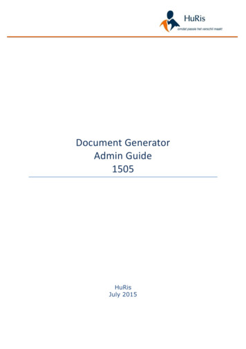
Pressing this button opens up the Radiance database manager to allow forcreation/removal/editing of surfaces:3.6.3.1. OpenThe Radiance database manager allows a user to open up a previous database (*.rdb fileextension) or to edit the current surfaces.Page 23 of 24
3.6.3.2. Add New SurfaceFor a new surface, the material category and a surface description must be added.3.6.3.3. Surf ColourThis allows for more detailed control of the Red, Green and Blue colour fractions for asurface.Page 24 of 24
3.4.3.5. Simulation Heating Unit Capacity This is used in dynamic thermal simulation only and the user can choose either unlimited plant capacity or can set a limit. 3.4.3.6. Cooling Plant Radiant Fraction The Cooling Device Radiant Fraction is the cooling that is seen as radiant energy, e.g. 0.0 for an air system. 3.4.3.7. Simulation Cooling .