Transcription
MEASUREMENTS OF THE D-REGION PLASMA USING ACTIVE FALLING PLASMAPROBESC. Baumann1 , H. Asmus2 , J. Schumacher3 , T. Staszak4 , N. Karow4 , A. Fencik4 , P. Schünemann4 , and B.Strelnikov21Deutsches Zentrum für Luft- und Raumfahrt, Institut für Physk der Atmosphäre, Oberpfaffenhofen, Germany2Leibniz-Institute for Atmospheric Physics, University of Rostock, Germany3Chair of Technical Electronics and Sensor Techniques at the University of Rostock, Germany4University of Rostock, Faculty of Mechanical Engineering and Marine Technology, GermanyABSTRACT1.MEDUSA is the acronym for MEasurements of the Dregion plasma USing Active falling plasma probes. Thescientific scope of MEDUSA is measuring small scalefluctuations in the plasma density of the D-region. Themeasurements enable investigations on the physics of theatmospheric phenomenon of polar mesospheric winterechoes (PMWE), which are radar echoes in the range of55-80 km. To observe the turbulence in that height region, we measure positive ion density and neutral density with our experiment. The MEDUSA experiment, asa part of the REXUS/BEXUS project, develops a newin-situ technique probing the lower ionosphere plasmaby two free falling units (FFU). These identical FFUscontain a sensitive structure that is exposed to the atmosphere. This structure consists of a grid, which surroundsan ion collector that is connected to a electrometer. Thecollector has a negative potential, the measured current atthe electrometer is proportional to the ion density measurements. The positively charged grid shields the collector from ambient electrons. Acceleration sensors inside each payload can be used to derive neutral gas density profiles from the FFU’s equation of motion. Theseneutral density profiles can be used to investigate possible correlations with the plasma densities. From thisdensity profile, assuming hydrostatic equilibrium one canintegrate a temperature profile. A GPS receiver on eachFFU provides in-situ horizontal information of all threephysical quantities (ion, neutral density and temperature)that has not been available in this scientific field before.During the REXUS 15/16 campaign a sounding rocketwill bring the two probes up to approximately 90 km,which are then ejected from the main payload. Duringdescend, the FFU will measure the ion density. The datawill be stored on the FFU directly and will also be sentto a ground station in case a recovery of the probe is notpossible. The rocket launch is supported by ground basedinstruments and model studies at winter polar latitudes.The Earth atmosphere is mostly influenced by solar radiation. It drives dynamical, chemical micro and macrophysical processes like turbulence and ionization in thewhole atmosphere. In the field of atmospheric researchthe polar summer mesopause region holds a prominantposition since it is the coldest place in the Earth’s atmosphere. Here, the phenomena noctilucent clouds (NLC)and polar mesospheric summer echoes (PMSE) are observed by ground based [e.g. 3] and in-situ measurements [e.g. 6]. The ionospheric state in this altitude region plays an important role for the PMSE phenomenaand other effects which are associated with enormous interest in nowadays geophysics. Besides the resonablyknown NLC and PMSE the small-scale structure of thelower D-region plasma at the high latitude ionosphere isconnected to the phenomena of polar mesosphere winter echoes (PMWE). PMWE are radar echoes which occur in the altitude range from 55-85 km during the polarwinter. The formation process is not fully understood,but theoretical approaches explain the formation by either turbulent or non-turbulent conditions. High electrondensities are likely to be essential for the echo formationprocess. These conditions are often fulfilled during highsolar activity causing enhanced ionization in the atmosphere [e.g. 2, and references therein]. Since at least ionsare connected to neutral gas dynamics [7], it is believedthat breaking gravity waves and the resulting shear windsand turbulence play an important role in the formation oflocal high plasma densities [4].Key words: FFU; Rocket Payload; Mesosphere; Turbulence; D-Region; Ion Density.INTRODUCTIONMEDUSA (Measurements of the D-region plasma usingactive falling plasma probes) is an experiment which isgoing to be flown on the REXUS 15 rocket in March2014.The aim of MEDUSA is to get a better understandingof turbulent processes in the mesosphere. In case ofPMWE conditions during the rocket flight we can actually gain information about the role of turbulence inPMWE physics. Ground based radar measurements willgive reasonable information if these conditions are ful-
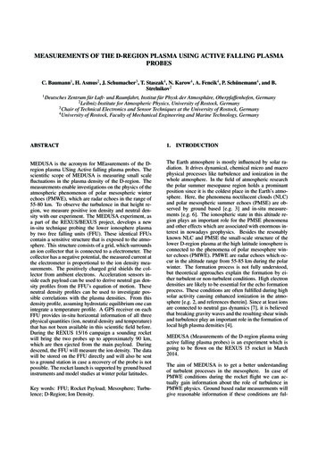
filled. The MEDUSA experiment consists of two autarcfree falling units (FFU). By applying two probes it is alsopossible to gain information about the horizontal dimensions of turbulence and PMWE.This paper covers the description of the MEDUSA experiment design and its components. In the following sections we present the concept of the experiment, the usedsensors, the mechanical design and the electronics.2.In Tab. 1 a timeline of our experiment during the rocketflight is shown. The main reason to eject our FFU beforethe apogee is that the tumbling of the rocket is minimalin this timeframe. During ejection we need to have a veryupright rocket orientation, since our sensors, situated inthe front of our FFU, has to point downwards to performreliable measurements.Table 1. Timeline for countdown and flightEventTime (T t)Monitoring-600sLift-off 0.00sBurn-out 26.00sYo-Yo despin 75.00sHatches open 76.00sExperiment Ejection 76.50sStart measurement 77.00sActivate wireless modem 79.00sMotor Separation 80.00sApogee 140.00sParachute release 270.00sSwitch Off System 730.00sLanding 800.00sCONCEPT OF THE EXPERIMENTThe concept of the MEDUSA experiment is described inthis section. See Fig. 1 for the conceptional overview.The MEDUSA experiment consist of two autarc freefalling units (FFU) mounted inside a REXUS module.These FFUs will be transported inside of the rocket payload up to an altitude of 80 to 90 km. Here the ejectionmechanism will be activated and both FFU will leave theREXUS rocket payload. Just after ejections of the FFUsAfter the successful flight, we aim at a successful recovery of both FFU by a helicopter team. Since we canhand over the latest received GPS data, we expect a goodchance of finding the landed FFU.3.SENSORSTwo main sensors are used inside of each FFU. Firstlywe use an electrostatic probe for the measurement of theion density in the D-region. Secondly, we use a three axisaccelerometer in each FFU to measure the atmosphericdrag.Figure 1. Concept drawing of the MEDUSA experimentthey start their measurements. Both FFUs carry identicalsensors, in order to receive receive horizontally resolvedmeasurements. Due to the fact that we can only measureduring the downleg of the rocket flight, it is crucial to obtain all data from both FFUs. Since a recovery of the FFUafter landing is not 100 percent secure, we use a telemetry system inside the FFU to send our data to the ground.For reasons of redundancy the data is also saved onboard.Below 30 km the FFU will leave the region of scientificinterest, since this altitude region below is also accessibleby balloon systems. The FFU recovery system will release a parachute at an altitude of approximately 5 km. Toreduce possible drift of the FFU due to the atmosphericwind, we will initiate the recovery system at this low altitude. The time for data transmission in this case is limited, since we expect to loose the telemetry signal at analtitude of approximately one kilometer.The electrostatic probe consists of a spherical grid arounda solid electrode. The grid is biased on payload potential while the electrode is biased negatively, thus the gridshields the electrode from ambient electrons and negativeions. At the same time positive ions are attracted by theelectrode. The current of positive ions reaching the electrode is proportional to the positive ion density [e.g. 7].This current is measured by a highly sensitive electrometer inside the FFU.The used accelerometer applies a capacitive method tomeasure the atmospheric drag. By solving the equation ofmotion of the FFU one can derive the atmospheric neutraldensity ρ.ρ 2m(az g)CD · A · v · Vz(1)Here, m is the mass of one FFU, az is the acceleration inz direction, g is the gravitational acceleration, CD is the
FFU s drag coefficient, A is the effective FFU crosssection, v the is the FFU s absolute velocity and Vz the FFUvelocity in vertical direction only. Under the assumptionof hydrostatic equilibrium one can also integrate the temperature profile along the flight path of both FFU.4.MECHANICSIn this section we describe the mechanical design of theMEDUSA experiment. In Fig. 2 the assembly of theMEDUSA experiment is shown. Since both FFUs areFigure 3. Fixation mechanism of the FFU inside of therocket moduleFigure 2. Experiment FFU mounted inside a rexus modulemounted inside a REXUS rocket module, an ejectionmechanism is used to liberate the FFU from the rocketmodule. Each FFU has a cylindrical form with a diameterof 80 mm and a length of 220 mm. The FFU frameworkhas bolts on the outside that fit into the channel of the riffled barrel that covers each FFU. For ejection we use aspring that pushes the FFU out of the module. While thespring acts, the bolts are guided along the channels of theriffled barrels. In that way the spring forces the FFU togain translational and rotational speed at the same time.Since the spring cannot rotate, there is a bearing betweenthe spring and FFU. The strength of the spring is designedthat after ejection the FFU has a spinning frequency of 12Hz and absolute speed of 1.8 m/s. The FFU are pointingdownwards with an limb angle of 27 , because we wantthat the electrostatic probe to point downwards while theFFU falls to the ground. Pointing downwards reduces theturbulent influence on the positive ion density measurement.Each FFU is fixed inside the rocket by three stamps (seeFig. 3). These stamps are locked by a wire around thecomplete FFU. At the point of ejection the wire is cut bya pyrocutter. Now a spring pushes the stamps out of thegrooves in the FFU hull.Since the rocket has to be sealed during takeoff, we havealso designed a system that allows to open a hatch so thatthe FFU to leave the rocket module (see Fig. 4). Thehatch opening system works as follows. There is a hatchon each side of the rocket module, one for each FFU.The hatches are locked during the start of the rocket, toavoid aerodynamical disturbances. The lock mechanismFigure 4. Ejection mechanism of the hatches, which coverthe holes in the rocket module, the lock mechanism is realised by a wire locking the hatches until ejection of theFFUis again realized by a wire that holds both hatches againstthe rocket module wall. This wire is cut by a pyrocutterjust before the FFU are released. Then springs, which aremounted right behind the hatches, can push the hatchesout of the rocket modules outer structure.4.1.Finite element method analysisDuring a rocket flight the experiments are exposed toaccelerating forces that are in the order of 20 times thegravitational acceleration. This extreme force during therocket’s liftoff puts an immense stress on the FFU andthe inner structure parts of our experiment. To test thestability of our experiment during a rocket flight we haveapplied an finite element method (FEM) analysis. FEMis a numerical technique that can be used to simulate thestress on a structure generated by a disruption, e.g. arocket start. In Fig. 5 we show the results of a FEManalysis where the FFU is mounted on the rocket payload.The force that acts on the module and FFU has been set to20 g, comparable to the force that act during an ImprovedOrion start. The derived quantity is the tension acting onthe FFU and rocket module during the rocket start. Thetension is colorcoded and given in units of MPa.The tension on the wall mounted brackets holding the
ion probebatterypackPCBsantennaframeworkGPS receiverparachuteFigure 6. Inner structure of the FFU, batteries in thefront, electronics on circuit boards and parachute in therear of the FFUFigure 5. Finite elements method analysis of the rocketmodule and the FFU, applied acceleration force is 20 g,result is the tension of the structure in MPaexperiments bulkhead is about one order of magnitudehigher than the tension acting on the FFU. The tensionon the brackets is apporximately 230 MPa which is a thelimit what steel can withstand. Further investigations onmore robust material is needed. On the contrary, the tension on the FFU stamps is only in the order of 10 MPa.This is due to the very light weight design of the FFU,resulting in a minimum of stress on the FFU structure.5.ELECTRONICSIn this section we describe the electronical system thatcontrols the MEDUSA experiment. At first there is a Onboard Communication Unit (OCU) mounted on the bulkhead of the rocket module. The OCU has the purposeto communicate with the REXUS service module and tocheck the status of the FFU. Another part of the OCU is agyroscope which monitors the attitude of the rocket. Weneed the attitude of the rocket during the moment of ejection, since the knowledge about the fall direction of theFFU is crucial for the MEDUSA experiment.Each FFU itself contains overall six sensors. The mainsensors are the positive ion probe, the accelerometer andthe GPS module. Onboard each FFU we have also anaddtional gyroscope, temperature sensors and a pressuresensor. In Fig. 6 you can see the inner parts of the probecovered by the glas fiber. We use glas fiber as cover material since it is transparent to the electro-magnetic telemetry signal. This material is necessary since we want tosend our data down to a groundstation by telemetry.The ion density sensor is primarily a sensitive two channel current to voltage converter circuit. It amplifies currents from a couple of nano amps up to 50 micro amps.The measuring range covers the typical ion currents mea-sured by electrostatic probes in the lower ionosphere. Thetwo channels provide two different amplifications of themeasured current. The output voltage will be convertedby analog digital converter (ADC) and the digital signalwill then be processed and send to the ground station bytelemetry as well as stored onto a flash drive on board theFFU.The accelerometer is assembled on a circuit board insidethe FFU (green plates in Fig. 6). Details on the performance and the details of the control electronics of the sensor can be found in [5].The GPS module will be used, to get the actual position of the probes, which is needed, to reconstruct thetrajectory for the flight results. Additionally, the position will be used to track the satellite during its fall withthe telemetry antenna of the ground station. This tracking achieves the best possible signal strength for the datacommunication. Caused by the CoCom formalities, mostGPS-receiver are limited in speed, acceleration and altitude that can be measured. That is why a module mustbe chosen that can be unlocked by the manufacturer, towork in the desired altitude of 30 km to about 80 km andvelocities of more than 500 m/s. The OEM615 by Novatel fulfils these requirements. It is a combined L1/L2receiver with an update rate of up to 50 Hz. Due to its dimension, it has to be mounted vertically into the system.The module can stand accelerations of up to 40 g and vibrations up to 7.7 grms. Additionally it can be operatedin a temperature range of -40 C to 85 C.Temperature sensors will be used on different pointswithin the system, e.g. near the batteries and the accelerometer. Monitoring the temperature is an importantpart of analyzing the housekeeping data. Using thesesensors, e.g. the charging of the batteries can be interrupted if they get too warm. Additionally, by loggingthis value, the temperature dependance of the sensors canbe corrected while analyzing their data. For that purposethe ”ADT7310” from ”Analog Devices” has been chosen.This sensor uses a SPI-Interface, which makes it easiy tobe integrated into the MEDUSA system. Additionally it
guarantees an accuracy of 0.5 and can interrupt the supervised part of the experiment if it exceeds a pre-definedtemperature limit.The pressure sensor will be used for the control of theparachute release. In cas of a failure of the GPS module,the measurement data of the pressure sensor will be usedto open the parachute in a predefined altitude. An absolute pressure sensor will be chosen to measure the atmospheric pressure. Its data will be compared with a lookup-table that contains the air pressure in relation to thealtitude and is stored in the microcontroller. ”FreescaleSemiconductors” offers a wide range of pressuresensorsthat could be used for that application. Their pressuresensors can be operated in a temperature range of -40 Cto 85 C minimum and have a digital output. Their measurement range start from 200 hPa, which corresponds toapproximately 10 km altitude.6.CONCLUSION AND OUTLOOKWe present the MEDUSA experiment design for theREXUS 15/16 student sounding rocket campaign, whichwill be flown in March 2014. This experiment includestwo autonomous FFU which will be ejected from therocket payload at maximum altitude. These FFU will beable to measure ion and neutral density in the altituderange from 80 - 50 km. The experiment focusses on theturbulent processes in the mesosphere and D-region ionosphere. Within that scope, we want to improve the understanding of processes in the mesosphere, like PMWE,which need further investigation on dynamics and coupling between the plasma and the neutral state of the atmosphere.Our experiment consists of a mechanism, that ejects theFFU from the rocket payload, a positive ion sensor, anacceloremter and a GPS module. By combining all threemeasured quantities, the positive ion density, neutral density and position information we can gain an insight intothe nature of the processes of the mesosphere. To gainhorizontal information about the turbulence is a major advance in this field. Horizontal changes in the turbulentstructure of neutral and charged ionosphere hasn’t beenanalyzed in the studies of [7], [1] and others. We wantto focus on these horizontal changes with our MEDUSAexperiment.ACKNOWLEDGMENTSThe authors acknowledge the opportunity given by theREXUS/BEXUS programme to fly the MEDUSA experiment on a rocket. We are also indebted to the financialsupport and help of the Leibniz Institute of AtmosphericPhysics in Kühlungsborn, the Institute of AtmosphericPhysics at the DLR in Oberpfaffenhofen and the electricaland mechanical engineering faculties of the University ofRostock.REFERENCES[1] TA Blix, EV Thrane, and Ø Andreassen. In situ measurements of the fine-scale structure and turbulencein the mesosphere and lower thermosphere by meansof electrostatic positive ion probes. Journal of Geophysical Research, 95(D5):5533–5548, 1990.[2] A. Brattli, T. A. Blix, O. Lie-Svendsen, U.-P. Hoppe,F.-J. Lübken, M. Rapp, W. Singer, R. Latteck, andM. Friedrich. Rocket measurements of positive ionsduring polar mesosphere winder echo conditions. Atmos. Chem. Phys., 6:5515–5524, 2006.[3] N Kaifler, G Baumgarten, J Fiedler, R Latteck,FJ Lübken, and M Rapp. Coincident measurementsof PMSE and NLC above ALOMAR (69 N, 16 E) byradar and lidar from 1999–2008. Atmos. Chem. Phys,11:1355–1366, 2011.[4] F.-J Lübken, B. Strelnikov, M. Rapp, W. Singer,R. Latteck, A. Brattli, U.-P Hoppe, and M. Friedrich.The thermal and dynamical state of the atmosphereduring polar mesosphere winter echoes. AtmosphericChemistry and Physics, 6(1):13–24, 2006.[5] J. Schumacher. High precision drag decelerationmeasurement system touse onboard active fallingspheres. Proc. ‘21th ESA Symposium on EuropeanRocket and Balloon Programmes and Related Research’, 2013.[6] B. Smiley, M. Rapp, T.A. Blix, S. Robertson, M. Horanyi, R. Latteck, and J. Fiedler. Charge and size distribution of mesospheric aerosol particles measuredinside NLC and PMSE during MIDAS MaCWAVE2002. Journal of Atmospheric and Solar-TerrestrialPhysics, 68:114 – 123, 2006.[7] E. V. Thrane and B. Grandal. Observations of finesclae structure in the mesosphere and lower thermosphere. Journal of Atmospheric and TerrestrialPhysics, 43:179–189, 1981.
the FFU to leave the rocket module (see Fig. 4). The hatch opening system works as follows. There is a hatch on each side of the rocket module, one for each FFU. The hatches are locked during the start of the rocket, to avoid aerodynamical disturbances. The lock mechanism Figure 3. Fixation mechanism of the FFU inside of the rocket module Figure 4.