Transcription
ISO/CD 19880-6: Draft 17 June 2020ISO TC 197/WG 23Secretariat: SCCGaseous hydrogen -- Fuelling stations -- Part 6: FittingsCD stageWarning for WDs and CDsThis document is not an ISO International Standard. It is distributed for review and comment. It is subject tochange without notice and may not be referred to as an International Standard.Recipients of this draft are invited to submit, with their comments, notification of any relevant patent rights ofwhich they are aware and to provide supporting documentation.
ISO 19880-6: Draft (a) ISO 2018All rights reserved. Unless otherwise specified, no part of this publication may be reproduced orutilized otherwise in any form or by any means, electronic or mechanical, including photocopying, orposting on the internet or an intranet, without prior written permission. Permission can be requestedfrom either ISO at the address below or ISO's member body in the country of the requester.ISO copyright officeCase postale 56 CH-1211 Geneva 20Tel. 41 22 749 01 11Fax 41 22 749 09 47E-mail copyright@iso.orgWeb www.iso.orgPublished in Switzerland.2 ISO #### – All rights reserved
ISO 19880-6: Draft (a)ContentsForeword . 5Introduction. 51 Scope. 7Figure 1 —Hose assembly and fitting . 82 Normative references . 83 Terms and definitions .104 General Requirements.114.1 General. 114.2 Intended Use. 114.3 Material Requirements. 125 General Test Methods .135.1 General. 135.2 Test Conditions. 145.3 Design Qualification Tests . 155.3.1 General. 155.3.2 External Leak Test . 155.3.3 Hydrostatic Burst Test. 165.3.4 Hydraulic Cyclic Endurance Test . 175.3.5 Gas Cyclic Endurance Test . 175.3.6 Rotary Flex Test . 195.3.7 Explosive Decompression. 205.3.8 Make and Break Test . 205.3.9 Cold Gas in Warm Fitting Test . 21Table 1. Hydraulic Cyclic Endurance Test Requirements .23 ISO #### – All rights reserved3
ISO 19880-6: Draft (a)6 Marking.246.1 Marking Information . 246.2 Marking Methods. 247 Component Literature .24Bibliography .244 ISO #### – All rights reserved
ForewordISO (the International Organization for Standardization) is a worldwide federation of nationalstandards bodies (ISO member bodies). The work of preparing International Standards is normallycarried out through ISO technical committees. Each member body interested in a subject for which atechnical committee has been established has the right to be represented on that committee.International organizations, governmental and non-governmental, in liaison with ISO, also take part inthe work. ISO collaborates closely with the International Electrotechnical Commission (IEC) on allmatters of electrotechnical standardization.The procedures used to develop this document and those intended for its further maintenance aredescribed in the ISO/IEC Directives, Part 1. In particular the different approval criteria needed for thedifferent types of ISO documents should be noted. This document was drafted in accordance with theeditorial rules of the ISO/IEC Directives, Part 2. www.iso.org/directivesAttention is drawn to the possibility that some of the elements of this document may be the subject ofpatent rights. ISO shall not be held responsible for identifying any or all such patent rights. Details ofany patent rights identified during the development of the document will be in the Introduction and/oron the ISO list of patent declarations received. www.iso.org/patentsAny trade name used in this document is information given for the convenience of users and does notconstitute an endorsement.For an explanation on the meaning of ISO specific terms and expressions related to conformityassessment, as well as information about ISO's adherence to the WTO principles in the TechnicalBarriers to Trade (TBT) see the following URL: Foreword - Supplementary informationThe committee responsible for this document is ISO/TC 197.IntroductionThis document will facilitate the development of hydrogen infrastructure that is needed to pave a wayfor the widespread deployment of hydrogen-fuelled vehicles. The successful commercialization ofhydrogen vehicle technologies requires codes and standards pertaining to fuelling stations, vehicle fuelsystem components, and the global homologation of standards requirements for technologies with thesame end use. Essentially this will allow manufacturers to achieve economies of scale by producing oneproduct for use globally.International harmonization contributes to reducing technical barriers and stimulates related markets.The development of a suite of standards that address hydrogen gas vehicles and fuelling stations isrequired. These standards will provide internationally homologized minimum safety performancecriteria at the component level, thus providing a foundation to build a safe “fuelling system.”5
This International Standard provides requirements for gaseous hydrogen fittings used in fuellingstation service.This document is based on the Canadian Standards Association reference CSA HGV 4.10 Fittings forcompressed hydrogen gas and hydrogen rich gas mixtures. This document is not intended to exclude anyspecific technologies that meet the performance requirements herein.This document is to be applied in conjunction with other International Standards relevant to hydrogenfuelling stations and components.6
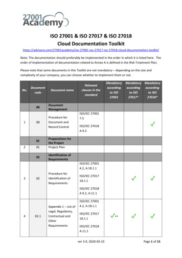
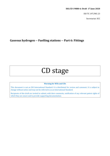
Gaseous hydrogen -- Fuelling stations -- Part 6: Fittings1 ScopeThis document specifies uniform methods for testing and evaluating the performance of fittings,including connectors and stud ends for ports, used with compressed hydrogen gas in hydrogen fuellingstation applications. It does not address special requirements for liquid and slush hydrogen.In this document, the term “fittings” includes fittings, connectors, and stud ends for ports. See Figure 1.This document does not apply to stand alone components, such as:1. Quick Action couplings, (i.e., quick connects);2. Fittings which are integral to stand-alone components, e.g., valves described in ISO 19880-3;devices covered in SAE J2600; Compressed Hydrogen Surface Vehicle Refueling ConnectionDevices; ISO 17268, Gaseous hydrogen land vehicle refuelling connection devices; andANSI/CSA HGV-4.4, Breakaway devices for compressed hydrogen dispensing hoses andsystems3. Flanges; or4. Welded or brazed joints.Fittings which are integral to stand-alone components are qualified per the specification for the standalone component.Example: Hose assembliesNOTE 1ISO 19880-5 has been developed primarily for hoses and hose assemblies for dispensing high pressure hydrogenfrom refuelling dispensers to hydrogen vehicles. Hose assemblies include the hose with connectors on each end(see Figure 1). Each connector has two basic functional elements that are addressed as described below:1)Coupling to hose. This function is defined by requirements and verified (along with the hose itself) byperformance-based tests in this document.2)Fitting for transition and connection to the piping system or equipment. This function is addressed byreference to appropriate hydrogen equipment standards and piping codes.7
Key1234567hose assemblymechanical jointfittingnipplecouplingcrimped sockethoseFigure 1 —Hose assembly and fittingThis document applies to newly manufactured fittings. It does not apply to fittings previously qualifiedfor hydrogen service by other relevant Nationally Recognized standards or regulations such as AFNOR,BSI, CGA, JIS, etc.All references to pressure throughout this document are to be considered gauge pressures, unlessotherwise specified.All dimensions used in this document are in metric units [International System of Units (SI)], unlessotherwise specified. If a value for a measurement, as given in this document, is followed by anequivalent value in other units, the first stated is to be regarded as the specification.2 Normative referencesThe following documents, in whole or in part, are normatively referenced in this document and areindispensable for its application. For dated references, only the edition cited applies. For undatedreferences, the latest edition of the referenced document (including any amendments) applies.Unless otherwise noted, the latest publications of the referenced documents8
shall be used.ASTM F1387-2005 Performance of Piping and Tubing Mechanically Attached FittingsIEC 60204-1:2016: Safety of machinery - Electrical equipment of machines - Part 1: General requirementsISO 6605 Hydraulic fluid power – Test Methods for hoses and hose assembliesISO 6743-4 Lubricants, industrial oils and related products (class L) -- Classification -- Part 4: Family H(Hydraulic systems)ISO 14687-2:2012: Hydrogen fuel -- Product specification -- Part 2: Proton exchange membrane (PEM) fuelcell applications for road vehiclesISO 19880-1: Gaseous Hydrogen – Fuelling Stations — Part 1: General requirementsISO 19880-3: Gaseous Hydrogen – Fuelling Stations – Part 3: ValvesISO 19880-5: Gaseous Hydrogen – Fuelling Stations – Part 5: Hoses and Hose Assemblies9
3 Terms and definitionsFor the purpose of this document, the terms and definitions given in ISO 19880-1 and the followingapply.3.1normal cm3/hrvolume measured over time measured at normal conditions of 0degC and 1 atmosphere, in cubiccentimeters per hour.3.2fittingdevice that connects tubes, hoses, or pipes to each other or to other system components3.3fitting assemblyfitting assembled to a mating tube, pipe, hose, or system component3.4hydrogen test gasgas whose composition complies with SAE J2719, or ISO 14687, used as the test medium3.5pipehollow tubular product conforming to the dimensional requirements for nominal pipe size (NPS) astabulated in ANSI B36.10 Welded and Seamless Wrought Steel Pipe, Table 23.6rated pressurethe manufacturer’s specified in-service internal pressure assigned to a mechanically attached fittingassembly. This value includes a maximum and minimum pressure. If no minimum pressure is stated, itis assumed to be atmospheric pressure3.7rated pressure/temperature envelopethe manufacturer’s specified in-service pressure and temperature operating ranges assigned to a fittingassembly3.8rated temperaturethe manufacturer’s specified in-service temperature assigned dependent on the temperature envelopeto a fitting assembly. This value includes a maximum and minimum temperature. If no minimumtemperature is stated, it is assumed to be -40 C. If no maximum temperature is stated, it is assumed tobe 85 C.3.9system componentindividual unit (for example, cylinder, valve, filter, but excluding piping) comprising one or more partsdesigned to be a functional part of a fluid system10
3.10test pressurea selected pressure used during testing that is based on the rated pressure of the fitting assembly, thepipe, or tube; whichever is lower, multiplied by the factor specified for each test3.11test samplea fitting assembly used for testing4 General Requirements4.1 GeneralThe requirements of this standard may be superseded by an application specific standard.The construction of parts not covered by this document shall be in accordance with reasonableconcepts of safety, substantiality and durability.All specifications as to construction may be satisfied by the requirements prescribed herein or in such away as to provide at least equivalent performance.Requirements for end fittings attached to hoses (hose assemblies) are found in ISO 19880-5.4.1.1 Safety AnalysisDesign safety analysis, such as Failure Modes and Effects Analysis (FMEA) and Process Failure Modesand Effects Analysis, shall be performed for fittings. The documents shall be made available for reviewon request to the certifying body.NOTE: FMEA is a methodology used in industry to identify potentially hazardous failure modes of safetydevices and recommend changes in design, manufacturing, inspection, and/or testing that eliminatesuch failure modes or minimize their effects. FMEA is applied to both device design and to themanufacturing and assembly process to identify corrective actions that improve device reliability andsafety. Available references include SAE J1739, “Potential Failure Mode and Effects Analysis in Design(Design FMEA), Potential Failure Mode and Effects Analysis in Manufacturing and Assembly Processes(Process FMEA), and Potential Failure Mode and Effects Analysis for Machinery (Machinery FMEA)”.4.2 Intended Use4.2.1 Hydrogen fuel qualityThe quality of hydrogen fuel dispensed to vehicles is defined in ISO 14687. The design, manufacture andoperation of fittings constructed in accordance with this document shall not introduce contamination tothe hydrogen passing through or in contact with them.4.2.2 Pressure ratingThe pressure rating of the fittings shall be equal to or above the dispenser pressure ratings. For further11
information regarding the relationships between pressure terms, see ISO 19880-1.4.3 Material Requirements4.3.1 GeneralMaterials shall be selected to minimize the risk of significant change in performance due to hydrogenembrittlement, stress corrosion, or hydrogen-induced fatigue failure during the service life of the fitting.4.3.2 Material restrictionsThe following materials shall not be used:Cast iron, malleable iron, and gray iron due to possibility of porosity of these materials in the context ofthe permeability of hydrogen,Aluminium.”Note 1:Aluminium is typically used for other components such as hydrogen ambient air vaporizers, cylinderbosses or valve bodies.Note 2:Contact between dissimilar metals should be avoided to prevent galvanic corrosion. When anelectrolyte is expected to be present, dissimilar metals between tubing, fittings and other componentsshould not be used. Anodic metals should not contact cathodic metals. Metal fittings should becompatible with metal tubing materials.4.3.3 Electrical BondingThe selection of materials and design shall ensure electrical bonding per IEC 60204-1.4.4 Product Quality4.4.1 GeneralThe manufacturer shall establish production processes with quality control measures to ensure thatproduction fittings meet requirements established in this document. As part of this requirement, ahydraulic proof pressure test at 150 % of the component pressure rating shall be conducted.Alternatively a gas leak test at 125 % of the component pressure rating may be conducted.4.4.2 Manufacturing and Production TestsManufacturing and production tests are intended to provide minimum quality control standards for thefitting.4.4.3 RecordsThe manufacturer shall establish documentation which describes the programs and proceduresspecified in Sections 4.4.4, and 4.4.5. The records shall be kept by the manufacturer in accordance with12
the manufacturers’ quality measures described in Section 4.4.1.4.4.4 TraceabilityThe manufacturer shall use a program to qualify raw materials, parts, assemblies and purchasedcomponents and provide traceability of all components (manufacture or purchased) used in theproduction of devices.4.4.5 Sampling PlanA sampling plan, selection of tests, and the frequency of the tests, shall be mutually agreed upon by themanufacturer and the certifying agency.4.4.6 Test MethodsThe manufacturer’s test method(s) shall specify the applicable tests described in this document.4.4.7 ResultsThe results of these tests and the program outlined in Section 4.4.2 shall be recorded and maintained bythe manufacturer for review by the certifying agency.5 General Test Methods5.1 General5.1.1 Testing periodsTests shall be conducted on the initial design and at any time changes are made in the design, material,or manufacturing process that could degrade the performance of mechanically attached fittings.5.1.2 AcceptanceAll fittings evaluated for continuous operation shall perform as intended without failure for therequired number of cycles.5.1.3 AgreementUnless otherwise specified, the number of samples and order of applicable tests shall be mutuallyagreed upon by the manufacturer and the certifying body.5.1.4 WaiversTests specified to establish the acceptance of a material for use in a fitting may be waived by thecertifying body when acceptable evidence in the form of a declaration, supplied by the manufacturer ofthe material, to substantiate its suitability for use in the expected environment, is submitted by the13
applicant.5.2 Test ConditionsAll tests shall be conducted over the range of sizes being qualified by the manufacturer. Interpolation ofsizes bounded by fitting sizes previously tested with similar design and appropriate calculations shallbe permitted.5.2.1 Test Sample5.2.1.1 Assembly InstructionsA fitting assembly shall be assembled in accordance with manufacturer’s instructions.5.2.1.2 Intermediate Fitting SizesAt least one intermediate size shall be tested if the minimum and maximum pipe or tube outsidediameter to be tested is equal to or greater than two.” Through reasonable interpolations betweenfitting sizes tested, all other sizes of fittings within the same type, grade (or combination of grades), andclass shall be considered acceptable if the fittings pass all of the testing requirements specified.5.2.2 PressureFittings shall be tested at the pressures to which they are rated. The ratings shall be stipulated in themanufacturers’ literature.5.2.3 Normal test temperatureFittings shall be tested at the temperatures to which they are rated. The ratings shall be stipulated inthe manufacturers’ literature.5.2.4 Specified test temperatureUnless stated otherwise, the tests specified herein shall be conducted at 20 C 5 C.5.2.5 Test Media5.2.5.1 GeneralUnless otherwise specified, tests shall be conducted using hydrogen as the test gas.Proper care should be exercised when working with hydrogen gas.5.2.5.2 PurgingPrior to testing with hydrogen gas, the fitting assembly shall be purged with nitrogen, helium, oranother non-reactive gas and then seal.14
5.2.6 Test sequenceThe test sequence shall be as agreed between supplier and testing agency.5.3 Design Qualification Tests5.3.1 GeneralDesign Qualification Tests are one-time tests used to qualify the design for a specific size, material,operating temperature, and pressure envelope.NOTE: The term “Type Test” is sometimes used to mean one-time design qualification test.If there is evidence of a fault in carrying out a test or an error in measurement, another test shall beperformed. If the results of this test are satisfactory, the results of the prior test shall not be a basis forrejection.5.3.2 External Leak Test5.3.2.1 ObjectiveThe objective of this test is to demonstrate the ability of the fitting assembled upon the tube or pipe tocontain the test gas.5.3.2.2 Method of Test5.3.2.2.1 Pre TestPrior to conditioning, purge the fitting assembly with nitrogen, or another non-reactive gas and thenseal it at 30 percent of rated pressure using the hydrogen test gas.Allow the test sample and test gas to stabilize to 20 C 5 C.The test sample shall either be bubble free or have a leakage rate less than 10 normal cm3/hr, (cubiccentimeter normal per hour); (0.6 cu.in. N/hr) (cubic inches normal per hour).5.3.2.2.2 Test ConditionsThree samples shall be tested. Each sample shall be tested at three sets of test conditions, definedbelow.The test is to be conducted at two pressures for each of three temperatures in the order shown below:A.Laboratory ambient temperature, 20 C 5 C: 10 bar (145 psi) or 10 percent of rated pressure, whichever is less; and 150 percent rated pressure.15
B.Low Temperature - minimum rated temperature or -40 C: 10 bar (145 psi) or 10 percent of rated pressure, whichever is less; and 150 percent rated pressure.C.High Temperature - maximum rated temperature, or 85 C: 10 bar (145 psi) or 10 percent of rated pressure, whichever is less; and 150 percent rated pressure.The test is conducted by:1.Placing the test sample into a temperature chamber and allowing the assembly to stabilize at theappropriate test temperature, as described above.2.Pressurizing test sample with test gas to the test pressure, as described above.3.Within five minutes, using a leak detecting fluid or hydrogen gas detector or other equallysensitive method, verify that the leak rate is in accordance with 5.3.2.3, Acceptance Criteria.5.3.2.3 Acceptance CriteriaThe acceptable leak rate shall be less than 10 normal cm3/hr., or no bubble formation for eachpressure/temperature set tested.5.3.2.4 Disposition of ComponentsParts used for this test may be used for other testing, used for actual service, or returned to stock.5.3.3 Hydrostatic Burst Test5.3.3.1 ObjectiveThe object of this test is to demonstrate the ability of a fitting assembly to withstand a minimum of four(4) times the rated pressure without failure.5.3.3.2 Method of Test5.3.3.2.1 Pre TestThere are no pretest conditioning activities.5.3.3.2.2 Test ConditionsThree fitting assemblies shall be used for this test. The test is to be conducted with the fluid as specifiedin Table 1, Hydraulic Cyclic Endurance Test Requirements by pressurizing16
each test sample to four (4) times the rated pressure.The pressure shall be increased at a rate not to exceed 16 percent of the fittings rated pressure persecond.5.3.3.3 Acceptance CriteriaNo rupture, burst, tearing or shearing of metal or catastrophic failure shall occur at four (4) times ratedpressure.5.3.3.4 Disposition of ComponentsParts used for this test shall not be used for other tests, used for actual service, or returned to stock.5.3.4 Hydraulic Cyclic Endurance Test5.3.4.1 ObjectiveThis test is to demonstrate the ability of a fitting to function as designed after 1 000 000 cycles at 133percent of the rated pressure.5.3.4.2 Method of Test5.3.4.2.1 Pre TestThere are no pretest conditioning activities.5.3.4.2.2 Test ProcedureThree fitting assemblies shall be used for this test.The hydraulic endurance test shall be conducted in accordance with the requirements specified in5.3.4.2.2, and Table 1, Hydraulic Cyclic Endurance Test Requirements.5.3.4.3 Acceptance CriteriaThe test sample shall be examined to demonstrate there is no rupture, burst, tearing or shearing ofmetal.After completion of 1 000 000 cycles the test sample shall pass section 5.3.2, External Leak Test.5.3.4.4 Disposition of ComponentsFollowing this test, including the External Leak Test described in section 5.3.2, parts used for this testshall not be used for other tests, used for actual service, or returned to stock.5.3.5 Gas Cyclic Endurance Test5.3.5.1 Objective17
This test supplements the 5.4, Hydraulic Cyclic Endurance Test, by adding a test that addresses theunique effects of testing with a gas (e.g. hydrogen versus with a hydraulic fluid). It tests only the highend of the pressure range, which has previously been viewed to be the “worst case”, and by keeping thepressure ratio to less than 2:1, it eliminates the explosive decompression testing issue caused byextremely rapid gas pressure cycling.Note: hydraulic cycling does not address explosive decompression.5.3.5.2 Method of Test5.3.5.2.1 Pre TestSee section 5.3.4.2.1 Pre Test.5.3.5.2.2 Test ProcedureThree fitting assemblies shall be tested.Each fitting assembly shall be tested using hydrogen, for 100 000 cycles of continuous operation.Cycling pressure shall be from 0,7 times rated pressure to 1,33 times rated pressure at a rate not toexceed 20 cycles per minute.1.Room Temperature Cycling:The fitting assembly shall be operated through 96 percent of the total cycles.2.High Temperature Cycling:The cycling procedure shall be repeated with the part stabilized at the appropriate maximumtemperature of 85 C, or the maximum rated temperature for 2 percent of the total cycles.3.Low Temperature Cycling:The cycling procedure shall be repeated with the part stabilized at -40 C for 2 percent of the totalcycles.5.3.5.3 Acceptance CriteriaThe test sample shall be examined to demonstrate there is no rupture, burst, tearing or shearing ofmetal.After completion of 100 000 cycles, the test sample shall pass section 5.3.2, External Leak Test.5.3.5.4 Disposition of ComponentsFollowing testing described in section 5.5, including the External Leak Test described in section 5.3.2,parts used for this test shall not be used for other tests, used for actual service, or returned to stock.18
5.3.6 Rotary Flex Test5.3.6.1 ObjectiveThis test shall determine if a fitting assembly can withstand a specified vibration without leakage orcomponent failure.Note: The vibration modelled is similar to the vibration mode expected with rotating equipment.5.3.6.2 Method of Test5.3.6.2.1 Pre TestSee section 5.3.2.2.1 Pre Test.5.3.6.2.2 Test ProcedureThree fitting assemblies shall be tested.A test sample shall conform to that described in ASTM F1387 -2005 Performance of Piping and TubingMechanically Attached Fittings, test procedure listed in section A10 Rotary Flex Test except using abending moment equivalent to 45 percent of actual tubing yield stress of the tubing material in sectionA10.4.3.Pressurize each test sample with hydrogen to 10 percent of rated pressure, but not to be less than 34KPa (5 psi).Apply a bending load to the end of the tube until the combined axial stress is 45 percent of the actualyield strength of the tubing material.Submit the test sample to a vibration or reverse bending moment of 30 5 Hz until failure or 1 000 000cycles, whichever comes first.5.3.6.3 Acceptance CriteriaThe fitting assembly shall be examined to demonstrate there is no rupture, burst, tearing or shearing ofmetal.Any leakage or failure of any component prior to completion of 1 000 000 cycles shall be considered afailure.After completion of 1 000 000 cycles the test sample shall pass
safety. Available references include SAE J1739,"Potential Failure Mode and Effects Analysis in Design (Design FMEA), Potential Failure Mode and Effects Analysis inManufacturingand Assembly Processes (Process FMEA), and Potential Failure Mode and Effects Analysis for Machinery (Machinery FMEA)". 4.2 Intended Use 4.2.1 Hydrogen fuel quality