Transcription
USING GNSS RAWMEASUREMENTS ONANDROID DEVICESWHITE PAPERTowards better location performancein mass market applications
2U S I N G G N S S R AW M E A S U R E M E N T S O N A N D R O I D D E V I C E SAbout the authors: The GSA GNSS Raw Measurements Task ForceLaunched in June 2017 and coordinated by the European GNSS Agency (GSA), the GNSS Raw Measurements TaskForce (Task Force) aims to share knowledge and expertise on Android raw measurements and its use, including itspotential for high accuracy positioning techniques relevant to mass market applications. The Task Force includesGNSS experts, scientists and GNSS market players, all of whom are dedicated to promoting a wider use of theseraw measurements.This white paper has been jointly drafted by the following Task Force members: European GNSS Agency (GSA) European Space Agency (ESA) Nottingham Geospatial Institute, University of Nottingham Airbus Defence and Space GmbHThe following Task Force members contributed with test results, revisions and comments: European Commission Joint Research Centre (JRC) European Satellite Service Provider (ESSP) French Civil Aviation University (ENAC) GNSS Centre of Excellence (GCE) Rokubun University of Rijeka University of Zagreb The French Institute of Science and Technology for Transport, Development and Networks (IFSTTAR) The Swedish Research Institute (RISE) WaysureThe authors would like to convey their thanks to all Task Force members, the full list of which canbe found at: sk-force.Special thanks also goes to Google for the valuable comments they provided.More information on the European Union is available on the Internet (http://europa.eu).Luxembourg: Publications Office of the European Union, 2017ISBN 978-92-9206-033-6doi: 10.2878/449581Copyright European GNSS Agency, 2017This document and the information contained in it is subject to applicable copyright and other intellectual property rights under the lawsof the Czech Republic and other states. Third parties may download, copy, print and provide the document in its entirety to other thirdparties provided that there is no alteration of any part of it. Information contained in the document may be excerpted, copied, printedand provided to third parties only under the condition that the source and copyright owner is clearly stated as follows: “Source: WhitePaper on using GNSS Raw Measurements on Android devices, copyright European GNSS Agency, 2017”.No part of this document, including any part of information contained therein, in whichever format, whether digital or otherwise, may bealtered, edited or changed without the European GNSS Agency’s prior express permission in writing to be requested under http://www.gsa.europa.eu/contact-us, clearly stating the element (document and/or information) and term of use requested. Should you becomeaware of any breach of the above terms of use, please notify the European GNSS Agency immediately, also through the above mentioned contact site. Any breach of these terms of use may be made subject to legal proceedings, seeking monetary damages and/or aninjunction to stop the unlawful use of the document and/or any information contained therein.By downloading, forwarding, and/or copying this document or any parts thereof, in whichever format, whether digital or otherwise, theuser acknowledges and accepts the above terms of use as applicable to him/her.The Android robot is reproduced or modified from work created and shared by Google andused according to terms described in the Creative Commons 3.0 Attribution License.
U S I N G G N S S R AW M E A S U R E M E N T S O N A N D R O I D D E V I C E STABLE OF CONTENTSTABLE OF CONTENTS3EXECUTIVE SUMMARY5DOCUMENT STRUCTURE61GNSS BASICS NEEDED FOR UNDERSTANDING RAW MEASUREMENTS71.11.21.31.47IntroductionGlobal Navigation Satellite SystemGNSS Receiver ArchitectureTime1.4.1 Introduction1.4.2 Reference times1.5 Navigation Message and Tracking Status1.6 Pseudorange Generation1.7 Position Estimation1.7.1 Single-GNSS constellation1.7.2 Multi-GNSS constellation288891013141415HOW TO ACCESS GNSS RAW MEASUREMENTS USING ANDROID APIS162.12.22.32.416IntroductionLocation API Before Android 7 - android.gsm.locationLocation API in Android 7Using GNSS Raw Measurements2.4.12.4.22.4.32.4.42.4.52.4.637GPS time generationPseudorange generationCarrier phase measurementsDopplerSatellite IDConstellation1617182020222324242.5 Raw Data Architecture2.6 Existing Applications and Devices24OPPORTUNITIES AND PRACTICAL USE OF GNSS RAW MEASUREMENTS273.1 Mobile A-GNSS Chipsets Overview3.2 Baseline Performance – Code Positioning3.3 Improving Position283.3.1 Multiple constellations3.3.2 Using information inside chipsets - Doppler smoothing of the code observables3.4 Taking It Beyond The Phone - Differential Observations3.4.1 Duty cycle3.4.2 Sensor fusion3.5 Educational and Scientific Applications3.6 High Integrity Solutions262930303133343737383
4U S I N G G N S S R AW M E A S U R E M E N T S O N A N D R O I D D E V I C E S4THE NEED AND USE CASES FOR HIGHER ACCURACY INTHE MASS MARKET4.1 Main Application Areas to Benefit from Improved Location Accuracy394.1.1 Mobile applications4.1.2 Safety-related applications4.1.3 Semi-professional applications39404041LIST OF FIGURES42LIST OF TABLES43ACRONYMS44REFERENCE DOCUMENTS45
U S I N G G N S S R AW M E A S U R E M E N T S O N A N D R O I D D E V I C E SEXECUTIVE SUMMARYIn May 2016, Google announced the availability of GNSS raw measurements from Android 7. For thefirst time, developers could access carrier and code measurements and decoded navigation messagesfrom mass-market devices.There are several advantages of using GNSS raw measurements on smartphones. Their use can lead toincreased GNSS performance, as it opens the door to more advanced GNSS processing techniques that,until now, have been restricted to more professional GNSS receivers. These benefits have been demonstrated through Code Based Positioning, Code Aided Positioning, Differential Positioning and PrecisePoint Positioning. Although in normal conditions the position calculated from GNSS raw measurementsmay not be as optimal as a typical chipset output, in certain cases, when applying external corrections,using GNSS raw data may lead to improved accuracy of the solution. Several application areas standto profit from this increased accuracy, such as augmented reality, location-based advertising, mobilehealth and asset management. The raw measurement allow also to optimise the multi-GNSS solutions,and to select the satellites based on their performances or differentiators. This is particularly relevantfor Galileo, that is operational since December 2016 and still completing the full deployment, butoffers already today excellent performances and signal advantages, such as the second frequency E5,and will offer soon differentiators such as the authentication on the Open Signal E1 and the PrecisePoint Positioning. For example, during the testing done to prepare this paper, it was possible to obtainGalileo-only positioning.The availability of raw measurements is interesting also from a technological innovation point of view.It enables more detailed testing and post-processing, which in turn serves as a great educationaltool. GNSS raw measurements may also support internal smartphone integrity by providing additionalsources of information and allowing for the exploitation of receiver autonomous integrity monitoringalgorithms.Despite these advantages and opportunities, using GNSS raw measurements was however not asstraightforward as it at first seemed. One year after the Google announcement only a few smartphoneapps were making use of Android GNSS raw measurements. Two main reasons could explain thislimited uptake. First, the GNSS experts may require assistance in understanding the specifics of rawmeasurements on Android. For example the standard formats, such as RINEX or NMEA, are not available on the Android platform. Secondly, the Java developers that are very familiar with the Androidenvironment, don’t usually understand the details of GNSS positioning.In order to address this knowledge gap, the white paper makes a link between the GNSS raw measurements and their implementation on the Android platform1. It presents useful information on generatingGNSS reference time and also step-by-step approach for deriving the pseudoranges from Android. Italso highlights the results of several testing activities, which showcase working solutions based onGNSS raw measurements and in particular Galileo.The White Paper is the combined work of several universities, public organisations and GNSS companies. The group, set up and coordinated by the European GNSS Agency (GSA), is known as the GNSS RawMeasurement Task Force.1The basic concepts of the raw measurements within this document are inspired by the Frank van Diggelen ION GNSS 2016’s Android 7GNSS raw measurements tutorial.5
6U S I N G G N S S R AW M E A S U R E M E N T S O N A N D R O I D D E V I C E SDOCUMENT STRUCTUREThe document is structured as follows: The first chapter provides a basic overview of GNSS, i.e. receiver architecture, GNSS time references,pseudoranges, navigation messages and position estimation. This introduction is focused on thenecessary theoretical basics that are needed to reconstruct GNSS raw measurements using Android. Chapter 2 describes how to access the raw measurements and the first steps for using them, e.g.generation of pseudoranges and Doppler. Raw measurements bring a new spectrum of accuracy techniques to Android devices, includingRTK and PPP. Chapter 3 depicts the most promising techniques and highlights the results collectedfrom different sources. Moreover, the benefits and limitations of each technique are detailed. The last chapter presents the use cases that may benefit from the increased accuracy and integrityobtained with the use of GNSS raw measurements.
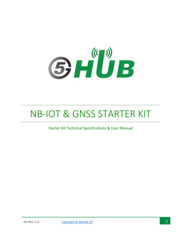
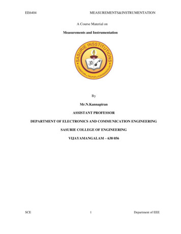
U S I N G G N S S R AW M E A S U R E M E N T S O N A N D R O I D D E V I C E S1 GNSS BASICS NEEDED FORUNDERSTANDING RAW MEASUREMENTS1.1 IntroductionThis section introduces the basic concepts of GNSS that are essential for understanding raw measurements and their use.This is primarily a synthesis of existing academic literature [RD-03, RD-04, RD-05]. Experienced GNSS users are recommended to move directly to Chapter 2.1.2 Global Navigation Satellite SystemThe GNSS space segment consists of various constellations of satellites orbiting Earth in MEO orbit, at an altitude of approximately 20 000 km and translating to the transmission delay of about 65 ms. There are currently four GNSS constellationsin operation or in deployment phase: GPS (USA), GLONASS (Russia), BeiDou (China) and Galileo (Europe) [RD-02]. These arecomplemented by several regional GNSS and augmentation systems.A user’s position is estimated using the distance measurements (pseudoranges) between the user’s receiver antennaand the position of at least four satellites. Both are determined by the receiver, which evaluates the satellite’s signal andnavigation message, respectively. This information is required by the PVT solution, which provides the user’s position andtime anywhere on the globe.213p2rp1rp3rrFigure 1: Intersecting spheres[RD-03]To determine the geometric range, all GNSS signals are modulated with a specific, few milliseconds long, Pseudo-RandomNoise (PRN) code that uniquely identifies the satellite. The receiver continuously compares and aligns a local copy of thePRN code with the received satellite signal. The measured delay of the received PRN code is equal to the transmission timeif the transmitter and receiver clocks are perfectly synchronised. The PRN code is superimposed by the navigation data bitscontaining the position of the transmitting satellite. Knowing one satellite position, the receiver position lies somewhereon a sphere around the satellite with a radius equal to the range. If the range measurements of three satellites are available, the three spheres intersect at two points. Since one point is not located close to Earth surface, the second point isthe true position of the receiver. In other words, the simultaneous measurement of the ranges to three satellites enablesthe determination of a fixed three-dimensional position, as illustrated in Figure 1. Due to the impact of the receiver clock,the three spheres do not intersect at a common point. This is estimated as the fourth unknown of the positioning problem,which is why at least four visible GNSS satellites are required [RD-03, RD-04, RD-05].7
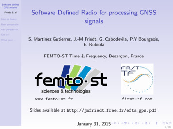
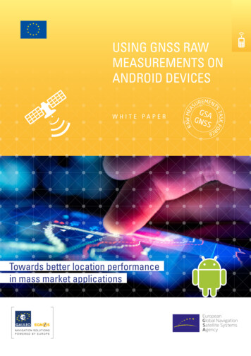
8U S I N G G N S S R AW M E A S U R E M E N T S O N A N D R O I D D E V I C E S1.3 GNSS Receiver ArchitectureA GNSS receiver process signals and provides the user with an estimated PVT solution. This PVT is based on the measuredpseudoranges, information delivered through the navigation message, and optional assistance and augmentation providedby third parties. A generic block diagram of a GNSS receiver is shown in Figure 2.The RF block (the left side of the diagram) includes the antenna and front-end, which are required for analogue signal processing. It can also include a low noise amplifier, filters and an intermediate-frequency down conversion. The final elementin the block is the Analogue-to-Digital Converter (ADC).In a smartphone, the base-band and PVT processing blocks (right side of the diagram) are software-based signal processingunits that are designed to operate on a general-purpose hardware. The baseband processing is responsible for acquiringand tracking of the GNSS signals and decoding the navigation messages. Assisted data (external information) can beprovided to reduce the time to fix.The baseband processing block provides the raw data to the PVT block, which then computes the receiver’s PVT. This processbenefits from augmentation data (e.g. EGNOS) or accelerometers (sensors fusion), improving the accuracy and availabilityin harsh environments.Raw DataNav MessageRF Front-EndADCBasebandProcessingRaw DataNav MessagePVTComputationPVTSats. InfoGNSS ChipsetExternalInformationExternalSensorsFigure 2: Generic block diagram of a GNSS receiverAndroid 7 users can use android.location Application Programming Interface (API) to access the raw data required tocalculate pseudoranges and decode navigation message (indicated by the red arrow on Figure 2). This data can be usedto explore new algorithms and applications for mass-market devices.The smartphone GNSS/navigation chip acts as a black box and only outputs the PVT and limited information from the trackedsatellites. Some highly integrated chipsets use tight integration with cellular, WiFi and Bluetooth. Some even use motion/orientation sensors for cross aiding, which improves the accuracy and availability of the final position. In most cases, it isrecommended to start your own algorithm using chipset PVT, periodically testing your solution against it.1.4 Time1.4.1 IntroductionWhile GNSS is best known for its positioning capabilities, it is also one of the most available and reliable sources ofprecise time.Time must be defined in a coherent and uniform way. Hence, transformations between the reference times used by thedifferent GNSS constellations are needed. Failing to account for this in a smartphone will lead to a reduction of the accuracy in the multi-constellation fix. Apart from a GNSS constellation’s time reference, a universal reference time systemis also defined, as further discussed in the following paragraph.
U S I N G G N S S R AW M E A S U R E M E N T S O N A N D R O I D D E V I C E S1.4.2 Reference timesThe Temps Atomique International (TAI) second duration was defined in 1967 as: The TAI second is the duration of 9 192631 770 periods of the radiation corresponding to the transition between the two hyperfine levels of the ground stateof the Caesium 133 atom.Universal Time (UT) is a solar time standard that reflects the average speed of the Earth’s rotation, its most commonlyused definition is known as UT1. Universal Time Coordinated (UTC) is the compromise between TAI and UT1. In fact, asan atomic time, UTC is as uniform as the TAI scale can be. However, in order to follow the Earth’s rotation variations, itis always kept within 0.9 seconds with respect to UT1. This is accomplished by adding or subtracting a certain numberof leap seconds to TAI.The main concepts of GNSS positioning are based on timing - a time of arrival and time of transmission of signals. EachGNSS uses its own reference time, as outlined in Table 1.Table 1: GNSS reference timesGNSS SystemGNSS reference timeGPSGPS Time (GPST)GalileoGalileo System Time (GST)GLONASSGLONASS Time (GLONASST)BeidouBeidou Time (BDT)1.4.2.1 GPS TimeGPS Time (GPST) is continuous with no leap seconds. It starts at midnight (0 h UTC) between 5 and 6 January 1980. Atthat epoch, the difference between TAI and UTC was 19 s.GPST is transmited using two parameters: Week Number (WN) and Time of Week (TOW). The first counts the weeksoccurred from the start of the GPS Time to the current week. The weeks begin at midnight on Saturday. TOW counts theseconds occurred within the current week.1.4.2.2 Galileo System TimeGalileo System Time is a continuous time scale starting 13 seconds before midnight between 21st August and 22ndAugust 1999, i.e. GST was equal to 13 seconds at 22nd August 1999 00:00:00 UTC. It was done so in order not to haveany difference between GPST and GST.1.4.2.3 GLONASS TimeGLONASS Time is generated by the GLONASS Central Synchroniser and the difference between the UTC from Russia(UTC(SU)). GLONASST should not exceed 1 ms 3 h:𝐺𝐿𝑂𝑁𝐴𝑆𝑆𝑇 𝑈𝑇𝐶(𝑆𝑈) 3ℎ 𝜏,where 𝜏 1𝑚𝑠. GLONASS implements leap seconds like UTC. GLONASST is based on the second of the day and the dayof the year.1.4.2.4 BeiDou TimeBeiDou Time (BDT) is a continuous time scale starting at 0 h UTC on 1 January 2006 and is steered towards UTC.1.4.2.5 Relationship of GNSS Reference TimesMulti-GNSS receivers can track and use different GNSS for the PVT solution. Usually, the receiver implements only oneclock based on one reference time. Table 2 presents the relationships between the GNSS reference times, the TAI, andthe relation between UTC and TAI. Figure 3 shows the time difference between the reference times and TAI.9
U S I N G G N S S R AW M E A S U R E M E N T S O N A N D R O I D D E V I C E STable 2: Relationships between Reference TimesSystemsRelationship𝑇𝐴𝐼 𝐺𝑃𝑆𝑇 19𝑠GPST - TAI𝑇𝐴𝐼 𝐺𝑆𝑇 19𝑠GST - TAI𝑇𝐴𝐼 𝐺𝐿𝑂𝑁𝐴𝑆𝑆𝑇 3ℎ NASST - TAI𝑈𝑇𝐶 𝑇𝐴𝐼 𝑙𝑒𝑎𝑝𝑠𝑒𝑐𝑜𝑛𝑑UTC-TAIUTC - TAI𝑇𝐴𝐼 𝐵𝐷𝑇 33𝑠BDT-TAIThe time difference in seconds between UTC and TAI is defined as leapsecond𝑈𝑇𝐶-𝑇𝐴𝐼. However, GNSS community describesthe leap second term as the time difference between UTC and GPS. The difference, at the time of writing, can be expressed as𝑙𝑒𝑎𝑝𝑠𝑒𝑐𝑜𝑛𝑑 ��-𝑇𝐴𝐼 19𝑠403530Time Difference 2020Figure 3: Time difference between reference timesGNSS receivers usually provide GNSS time in GPS System Time, which requires a conversion of GLONASS measurements –𝐺𝑃𝑆𝑇 𝐺𝐿𝑂𝑁𝐴𝑆𝑆𝑇 3ℎ 𝑙𝑒𝑎𝑝𝑠𝑒𝑐𝑜𝑛𝑑, to generate the GLONASS pseudoranges based on the Android raw data.1.5 Navigation Message and Tracking StatusThe receiver needs to synchronise with the satellite transmitted signal. Currently, GPS transmits four different signals in L1[RD-09], with the Coarse/Acquisition (C/A) code signal being the most important and most often used signal for mass-marketdevices. The PRN code is based on a 1-ms length code at a chipping rate of 1.023 chips per ms. A local replica of the C/Acode is generated with the proper delay and Doppler. Figure 4 shows a perfect synchronisation between the periodical C/Acode, transmitted by the satellite (repeated every 1 ms), and its local replica generated by the receiver (in blue).At this stage, the receiver is not able to provide the full transmitted time, and only fractional pseudoranges are available.For instance, at 𝑡0, the receiver can only provide the relative delay to the beginning of the C/A code period. In the same way,at 𝑡1, the receiver provides the delay to the beginning of the current C/A code. The number of entire C/A codes between 𝑡0and 𝑡1 is unknown.
U S I N G G N S S R AW M E A S U R E M E N T S O N A N D R O I D D E V I C E SIf the receiver is only synchronised with the C/A code, the valid range of the transmitted time is from 0 to 1 ms, makingthe computation of the travel-time ambiguous.C/A CodeC/A Code1 ms1 msSatelliteSignal1 ChipLocalReplicaSatellite/GNSS timeFigure 4: Synchronisation with the C/A codeTo solve this time ambiguity, the receiver can exploit the navigation message structure. Figure 5 shows the different synchronisation stages required by the receiver to obtain the satellite time: Code Lock: the receiver is locked to the C/A code. The valid range is 0–1 ms.Bit Sync: the receiver is synchronised with the bits. The valid range is 0–20 ms.Subframe Sync: the receiver is synchronised with the subframes. The valid range is 0–6 s.TOW Decoded: all the subframes contain the TOW. Therefore, once the TOW is decoded, the valid range is 0–1 week.Existing literature describes more advanced algorithms capable of computing the PVT solution using only fractional pseudorange. This navigation solution is known as a coarse-time navigation problem [RD-10]. Furthermore, A-GNSS receiverscan also obtain the TOW through external systems and do not need to decode the broadcasted message.In the case of GPS, five consecutive subframes construct a frame, with a navigation message formed by 25 frames. Moreinformation related to the GPS message structure can be found in [RD-09].1 Sub-frame5 Sub-frame TOW6sSub-frame Sync1 Bit300 Bit 20 msBit Sync1 C/A20 C/A 1 msCode Lock1 Chip 1023 ChipsFigure 5: GPS L1 C/A code and navigation message structure11
12U S I N G G N S S R AW M E A S U R E M E N T S O N A N D R O I D D E V I C E SGalileo uses the E1 Open Service (OS) modulation - the multiplexing of two components: E1B: the E1 OS Data component. It is generated from the I/NAV navigation data stream and the primary code (E1BC). E1C: the E1 OS Pilot component. It is composed of the primary code (E1BC) and the secondary code (E1C 2nd).Figure 6 shows the structure of both the E1B and E1C components. The first is based on a primary code E1BC with a lengthof 4 ms, with the symbols of the same length as the E1BC code. The pages (I/NAV service) are composed of 500 symbols,including the TOW. A sub-frame is composed of 15 pages. The full I/NAV message is composed of 34 subframes.The pilot component is composed of a primary code with a length of 4 ms and with a secondary code E1C 2nd placed ontop of it. It is 25 chips long, with each chip lasting 4 ms. The full secondary code has a length of 100 ms. Since there is nonavigation message in the pilot component, the receiver can track the signal coherently for longer periods, allowing it toreceive a much weaker signal. Many receivers track the pilot component when the ephemerides and clocks are obtainedthrough external sources or decoded from the navigation message.Once the receiver is synchronised with the satellite signal and it has obtained GNSS time, the unambiguous transmittedtime can be computed. GNSS time can also be obtained from external sources, but these methods is outside the scopeof this document. Tracking the secondary Galileo code results in a time ambiguity of 100 ms. As the time that the signaltravels from the satellite to the receiver is 70 ms, the full pseudorange can be easily generated, unlike the GPS one.E1B Galileo Component(Data)I/NAV page 1E1C Galileo Component(Pilot)I/NAV Page 15 TOW2sE1B page Sync1 SymbolE1C 2nd Code100 msE1C 2nd Code Lock500 Symbol 1 E1BC Code1 E1BC CodeE1C 2nd Code 4 msE1BC Code Lock500 E1BC Code 25 E1BC Code 4 msE1BC Code Lock1 Chip 1 Chip4092 Chips4 092 Chips Figure 6: E1B Galileo component (left side) and E1C Galileo component (right side)The structure of Beidou and GLONASS navigation messages and the tracking status are similar to GPS. Table 3 summarisestime ambiguity and the tracking status for the four main constellations.Table 3: Time ambiguity based on the tracking statusGPSGALILEOGLONASSBeiDouSync StatusTimeSync StatusTimeSync StatusTimeSync StatusTimeC/A code1 msE1BC code4 msC/A code1 msC/A code1 msBit20 msE1C 2nd code100 msBit20 msBit20 msSubframe sync6sE1B page2sString2sSubframe sync6sTOW1 weekTOW1 weekTime of Day1 dayTOW1 week
U S I N G G N S S R AW M E A S U R E M E N T S O N A N D R O I D D E V I C E S1.6 Pseudorange GenerationAlthough the concept of the pseudorange is simple, its generation is anything but straightforward, as this measurement ofdistance is obtained through time measurements. GNSS receivers process the received signals to obtain the transmitted(𝑡𝑇𝑥) and received time (𝑡𝑅𝑥). The difference of both is the signal’s time of travel from the satellite to the receiver (assumingno extra delays due to ionosphere, troposphere and other elements). The pseudorange can be computed as𝜌 (𝑡𝑅𝑥 𝑡𝑇𝑥) 𝑐,where 𝑐 is the speed of light in vacuum. 𝑡𝑇𝑥 is also needed to compute the satellite position.Pseudorange generation and PVT computation can be implemented through two different methods: common receptiontime or common transmission time [RD-11]. In the following paragraphs, pseudorange generation is based on the commonreception time method.Common reception time is known as the measurement time (). Four satellites transmit the signals at the same time,with the same TOW being transmitted by all the satellites at the same time epoch (left side of Figure 7). Due to differentpropagation paths, the four signals arrive at the receiver with different delays. The receiver then computes the time offsetbetween the TOW and the current time at the epoch. This is known as the measurement time (). As a result, the transmitted satellite times (provided in GNSS system time) at measurement time can be expressed aswhereis the transmitted TOW andTowSatellite 1TowSatellite 2TowSatellite 3TowSatellite 4is the delay between the TOW and the measurement time.TowTowTowTowGNSS TimeRx timeFigure 7: Pseudorange computation based on common reception timeBefore it computes the first PVT and decodes the TOW from at least one satellite, the receiver has no information about theGNSS time. Thus, it must make assumptions in order to generate the Rx time and to compute the first set of pseudoranges.The first satellite signal to arrive is used as a reference. The received time () is the transmitted time plus a referencepropagation time (). A standard value between 65 and 85 ms is usually assumed. Therefore, the first measured timecan be computed as:13
14U S I N G G N S S R AW M E A S U R E M E N T S O N A N D R O I D D E V I C E SAll other pseudoranges are generated relative to the first one. As constant error to all the satellites is present (sincehas been fixed, not estimated), a bias between the GNSS and the received time is introduced ( ). The measurement time,in GNSS reference time, can be expressed as:where is the -th measurement time. Once the first set of pseudoranges has been computed and the first PVT obtained,is determined and used for all the following sets of pseudoranges. However, the receiver computes and updates theclock bias in all PVT sets. Therefore, the following sets of pseudoranges can be computed as:where is the speed of light in vacuum. Some receivers can provide theand an offset.as the sum of the measurement time1.7 Position Estimation1.7.1 Single-GNSS constellationNeglecting further impacts on the pseudorange, the range measurement between the receiver antenna and the -thsatellite consists of the real range and the receiver clock error multiplied by the speed of light in vacuum:The aim is to estimate the receiver antenna coordinatesand the clock offsetfrom a set of pseudorange measurements . Knowing the positionof the -th satellite obtained from the transmitted navigation message orother external sources, the pseudorange can be rewritten as:The simultaneous range measurements to at least four satellites in view is sufficient to solve the problem. As the equationdefines a non-linear system, we solve it with an iterative linearization, starting from an approximate positionof the receiver:whereand the approximate solutionmatrix notation as:andis the computed range to satellite based on its coordinatesof the receiver’s position. The equation system can be expressed inTo solve for the four unknowns, at least four satellites in view are necessary. As the pseudorange contains various sourcesof error (Figure 8), it is beneficial to use all available pseudorange measurements to estimate the position.For more than four satellites (n 4), an over-determined system is obtained, which can be solved using the non-linearleast-squares (or related Kalman filter) estimation procedure. After solving the equation, the updated estimate of thereceiver coordinates is:In a consecutive step, this pseudorange equations can be linearized again using the updated receiver position.These steps are repeated until the difference between two consecutive iterations is below a given threshold. Furtherdetails regarding positioning are given in [RD-12, RD-13, RD-14].
U S I N G G N S S R AW M E A S U R E M E N T S O N A N D R O I D D E V I C E S 300 mEmissionReceptionSatellite clock offsetup to hundreds of kmRelativistic clock correction 13 mSatellite instrumental delay mPseudorangeGeometric range: 𝑝𝑝 20.000 kmIonospheric delay 2 - 30 mTropospheric delay 2 - 30 mReceiver clock offset 300 kmReceiver instrumental delay mFigure 8: Sources of GNSS pseudorange measurement errors[RD-05]1.7.2 Multi-GNSS constellationMultiple GNSS constellations can be used to solve the position solution. In harsh environments, a combination of
2 HOW TO ACCESS GNSS RAW MEASUREMENTS USING ANDROID APIS 16 2.1 Introduction 16 2.2 Location API Before Android 7 - android.gsm.location 16 2.3 Location API in Android 7 17 2.4 Using GNSS Raw Measurements 18 2.4.1 GPS time generation 20 2.4.2 Pseudorange generation 20 2.4.3 Carrier phase measurements 22 2.4.4 Doppler 23