Transcription
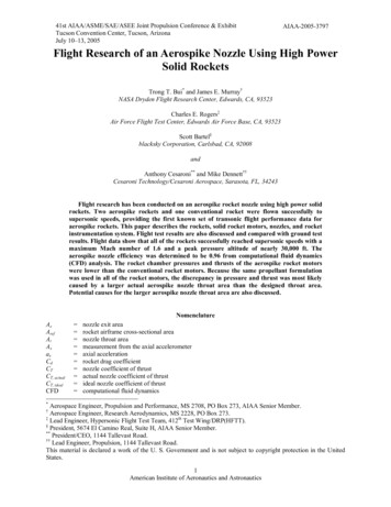
41st AIAA/ASME/SAE/ASEE Joint Propulsion Conference & ExhibitTucson Convention Center, Tucson, ArizonaJuly 10–13, 2005AIAA-2005-3797Flight Research of an Aerospike Nozzle Using High PowerSolid RocketsTrong T. Bui* and James E. Murray†NASA Dryden Flight Research Center, Edwards, CA, 93523Charles E. Rogers‡Air Force Flight Test Center, Edwards Air Force Base, CA, 93523Scott Bartel§blacksky Corporation, Carlsbad, CA, 92008andAnthony Cesaroni** and Mike Dennett††Cesaroni Technology/Cesaroni Aerospace, Sarasota, FL, 34243Flight research has been conducted on an aerospike rocket nozzle using high power solidrockets. Two aerospike rockets and one conventional rocket were flown successfully tosupersonic speeds, providing the first known set of transonic flight performance data foraerospike rockets. This paper describes the rockets, solid rocket motors, nozzles, and rocketinstrumentation system. Flight test results are also discussed and compared with ground testresults. Flight data show that all of the rockets successfully reached supersonic speeds with amaximum Mach number of 1.6 and a peak pressure altitude of nearly 30,000 ft. Theaerospike nozzle efficiency was determined to be 0.96 from computational fluid dynamics(CFD) analysis. The rocket chamber pressures and thrusts of the aerospike rocket motorswere lower than the conventional rocket motors. Because the same propellant formulationwas used in all of the rocket motors, the discrepancy in pressure and thrust was most likelycaused by a larger actual aerospike nozzle throat area than the designed throat area.Potential causes for the larger aerospike nozzle throat area are also discussed.NomenclatureAeArefAtAxaxCdCTCT, actualCT, idealCFD nozzle exit arearocket airframe cross-sectional areanozzle throat areameasurement from the axial accelerometeraxial accelerationrocket drag coefficientnozzle coefficient of thrustactual nozzle coefficient of thrustideal nozzle coefficient of thrustcomputational fluid dynamics*Aerospace Engineer, Propulsion and Performance, MS 2708, PO Box 273, AIAA Senior Member.Aerospace Engineer, Research Aerodynamics, MS 2228, PO Box 273.‡Lead Engineer, Hypersonic Flight Test Team, 412th Test Wing/DRP(HFTT).§President, 5674 El Camino Real, Suite H, AIAA Senior Member.**President/CEO, 1144 Tallevast Road.††Lead Engineer, Propulsion, 1144 Tallevast Road.This material is declared a work of the U. S. Government and is not subject to copyright protection in the UnitedStates.†1American Institute of Aeronautics and Astronautics
dDFADSFxgISPMmm&PaPcpsigrTtuxU xγηtρ θ diameterexternal aerodynamic drag of the rocketflush air data systemforces in the axial directiongravitational accelerationspecific impulseMach numberrocket massrocket propellant mass flow rateambient pressurerocket chamber pressurepounds per square inch gageradiusrocket motor thrusttimerocket velocity in the axial directionfreestream velocityaxial directionspecific heat rationozzle efficiency factorfreestream densityrocket elevation angleI. IntroductionHE broad range of human and robotic space exploration missions to the Moon, Mars, and destinations beyond,as outlined in the President’s Space Exploration Vision, will benefit from advances in technology from allsystems of a space vehicle, including the propulsion system and its nozzle. Most space vehicles, including spacelaunch boosters, Moon and Mars landers, orbiters, space tugs, or deep-space interplanetary probes, rely on a nozzleto convert the energy generated in the propulsion system into the direct thrust necessary to propel them throughspace. This is true for chemical, nuclear thermal, solar-heating, and arc-heating rockets. Therefore, nozzle efficiencyand its physical size have a primary effect on the overall performance of space vehicles. Increased nozzleefficiencies and shorter nozzle lengths translate directly into less weight, more payload, longer range, and lowercosts across the entire spectrum of space vehicles.Reference 1 provides a broad review of advanced rocket nozzle technologies. In this reference, it is shown thataltitude-compensating nozzle technologies, such as the expansion-deflection nozzle, aerospike or plug nozzle, dualbell nozzle, and dual-expander nozzle, can provide significant performance gains by adapting the nozzle exhaustflow to changes in ambient pressure.One of the promising altitude-compensating nozzle technologies that has received considerable attention fromthe aerospace research community is the aerospike nozzle. A good discussion on the aerospike nozzle flow physicscan be found in reference 2. For solid rocket motors, an aerospike nozzle was designed, built, and ground tested byJohnson and Leary.3 Besnard, Chen, Mueller, and Garvey4 designed, fabricated, and ground tested an aerospikenozzle for liquid rocket engines as part of the California Launch Vehicle Education Initiative (CALVEIN). TheCALVEIN aerospike effort eventually resulted in the first known flight of a liquid-fueled aerospike rocket inDecember 2003.In addition to the altitude-compensation ability, aerospike nozzles can provide more thrust in the vacuum ofspace or on the Moon. Compared to the 50:1 ratio nozzles used on the Apollo Lunar Excursion Module descent andascent stages, as well as the Apollo Service Module, aerospike rocket nozzles with expansion ratios of 200:1 to300:1 would increase thrust and specific impulse by 5 to 6 percent. For the high Delta-V demands of orbital transfersystems, as well as the descent and ascent stages for missions to the Moon and Mars, a 5 to 6 percent increase inspecific impulse could result in an approximate 8 to 9 percent decrease in propellant mass. This significant masssavings lowers the total vehicle mass for a Moon or Mars mission and provides margin for other critical vehiclesystems or payloads. Truncated aerospike nozzles also have the advantage of being more compact than conventionalbell nozzles for in-space applications.In addition to space exploration applications, the aerospike nozzles can offer advantages in defense applicationssuch as air-to-air, ground-to-ground, and ground-to-air missile systems. Many current tactical missile systems haveT2American Institute of Aeronautics and Astronautics
fixed, non-adaptive nozzles. Yet even air-to-air missiles might be launched from a wide range of altitudes againsttargets at yet different altitudes. Also each missile trajectory might cover a wide range of altitudes during normaloperation. Altitude-compensating nozzles such as the aerospike nozzles might increase the performance of a missilesystem without the mechanical complexity of the conventional variable nozzles.Although the advantages of altitude-compensating rocket nozzle technologies are well known through analysisand ground testing, the lack of actual atmospheric flight research data has hindered the use of these nozzles incurrent as well as a next generation of space vehicles. A comprehensive flight test data base, and preferably, actualrocket flights with altitude-compensating nozzles, such as the aerospike nozzles, are necessary before these nozzlescan be seriously considered for actual application on space vehicles.The current effort addresses the lack of atmospheric flight research data on altitude-compensating rocket nozzlesby conducting transonic flight research and demonstration of an aerospike rocket nozzle using high power solidfueled rockets within the atmosphere. The research approach is described in this paper. Results from analysis,ground tests, and actual rocket flight tests are presented and discussed.Trade names and trademarks are used in this report for identification only. Their usage does not constitute anofficial endorsement either expressed or implied, by the National Aeronautics and Space Administration.II. Research ApproachRapid progress in aerospace technologies requires a constant interplay between analysis, ground testing, andflight testing activities. All three of these activities are equally important. Testing, both on the ground and in flight,keeps analysis well-grounded and relevant, while analysis provides the foundation and explains flight and groundtest results. Often, the sparks of insight gleaned from one of these activities greatly benefits the other two, if all threeactivities are done in concert, accelerating the maturation of advanced aerospace technologies.Figure 1 summarizes the approach of the current research effort. During a two-year period and with a smalldiscretionary budget, a comprehensive effort was undertaken with analysis, ground testing, as well as flight-testing,all conducted in a complementary and integrated manner. In this project, an aerospike solid-fueled rocket nozzle wasdesigned, built, ground tested, and flight tested. This aerospike nozzle was successfully used to power two solidfueled rockets to supersonic flight speeds on two consecutive flights, providing the first known set of transonic flightperformance data for aerospike rockets. A conventional conical nozzle rocket with an identical configuration wasalso flown to supersonic speeds, providing valuable baseline comparison data. Key to this effort is a cost-effective,high-speed flight research rocket vehicle utilizing consumer-grade high power rocketry techniques, procedures, andmaterials. Also, resources and personnel from the high power rocketry organizations such as the Tripoli RocketryAssociation (Orem, UT) were critical to the success of this project. Hopefully this new flight research vehicle willallow new propulsion concepts and small research payloads to take flight quickly and frequently, helping to bridgethe gap that currently exists between analysis, ground testing, and flight for advanced aerospace technologies.3American Institute of Aeronautics and Astronautics
Figure 1. Current Research Effort Includes Analysis, Ground Testing, and Flight Testing.A. Rocket Test VehicleThe Optimal 168 rocket from blacksky Corporation (Carlsbad, CA) was used as the primary rocket test vehiclefor this flight research effort. Engineering drawings of the Optimal 168 rocket are shown in figure 2 below, bothwith the aerospike rocket nozzle as well as the conventional conical nozzle. The total lift-off weight of the rockettest vehicle is just under 100 lb. The aerospike rocket is 125.32 in. long from the virtual rocket nose cone tip to theend of the aerospike nozzle plug. The conventional rocket is 120.70 in. long. The rocket airframe is a single piece ofextruded 6061 aluminum tube with a nominal outer diameter of 6.63 inches. The fiberglass nose cone is a simplecone with a total conical angle of 10 deg. This nose cone geometry was chosen because an extensive aerodynamicdatabase is available for this simple geometric shape. The rocket nose cone has a stainless steel nose tip whichhouses a total pressure port with a port inlet diameter of 0.125 in. A simple Flush Air Data System (FADS)5,consisting of a set of four wall static pressure ports on the nose cone, is used to determine the incoming freestreamflow angle. The FADS pressure ports are located 26.62 in. from the virtual nose tip and distributed circumferentiallyaround the nose cone at equal 90-deg intervals. One wall static pressure port is also located on the rocket airframe at66.54 in. from the virtual nose tip. The nose cone total pressure port and static pressure ports, as well as the airframestatic pressure port, provide the air data measurements necessary to determine the rocket flight Mach number,pressure altitude, and incoming freestream flow angles. To minimize lags in pressure measurements, all of the nosecone pressure transducers are mounted within the nose cone itself. Two other pressure transducers are mountedinside the rocket airframe: the rocket chamber gage pressure transducer and the internal reference pressuretransducer, used to provide the reference pressure for the rocket chamber gage pressure measurement.4American Institute of Aeronautics and Astronautics
Figure 2. Engineering Drawings of the Aerospike Rocket and the Conventional Rocket Used in the DrydenAerospike Rocket Test.The rocket recovery system is located directly below the nose cone, consisting of the parachute system, twoblacksky AltAcc altimeter and accelerometer data acquisition and recovery controllers, and an Advanced Retentionand Release Device (ARRD) – a pyrotechnic release device for the main chute. The parachute pack has one 5-ftdiameter drogue chute and one 12-ft diameter main chute. Actuated by the dual-redundant AltAcc onboardcontrollers, the drogue chute deploys at minimum rocket velocity (apogee). Then the main chute deploys when therocket descends to approximately 2500 ft above ground level and the ARRD is fired. Two VHF homing beaconradio transmitters with different manufacturers and frequencies are secured to the rocket chute harnesses to aid inlocating the rocket after it lands. The rocket flight data acquisition system is mounted inside the rocket airframedirectly below the rocket recovery package. The four rocket fins are formed from sheets of 5053 aluminum alloy andanodized red. From analysis, it was determined that the center-of-pressure (CP) of the rocket is always at least tworocket diameters behind its center of gravity (CG), ensuring stable flight throughout the rocket trajectory.The vast majority of the rocket systems, including the rocket hardware, flight data acquisition electronics,sensors, recovery system, and recovery electronics are commercially available and thus are low-cost, low-risk items.The aerospike nozzle is the only “new” and high-risk item in this research effort. The chance for success in a flightresearch project greatly increases if the number of “new” and high-risk items is kept to the minimum (only one inthis effort).5American Institute of Aeronautics and Astronautics
B. Solid Rocket MotorThe solid rocket motor used in this effort was developed by Cesaroni Technology Incorporated (CTI, Sarasota,FL), from the CTI Pro150 O5100 consumer high power rocketry motor. This solid rocket motor has aninterchangeable nozzle assembly so that the same rocket motor can be used with the aerospike nozzle as well as theconventional conical nozzle. The Pro150 motor was originally developed as the prototype solid-fueled booster forthe U.S. Navy Affordable Weapons Program, in which the Pro150 motor was used to launch a small turbojetpowered cruise missile. The Pro150 motor has a reusable 6061 aluminum alloy case and uses ammoniumperchlorate composite propellant (APCP). The current propellant has less aluminum metal content than the standardPro150 motor to minimize solid-gaseous multiphase flow in the aerospike nozzle. The propellant weight for allmotors used in the current effort is 28.53 0.09 lb per motor.C. Rocket Instrumentation SystemThe custom-made onboard rocket instrumentation system is based on the Tattletale Model 8 data logger (OnsetComputer, Bourne, MA) integrated with the CF-8 compact flash nonvolatile memory module (Persistor Instruments,Bourne, MA). NASA Dryden-designed power supply and signal conditioning boards provide regulated excitation,gain, offset, and low-pass anti-aliasing filtering for each sensor channel. Dual-redundant rechargeable lithiumbattery packs provide all required power.The entire rocket sensor suite consists of 14 transducers in 15 data acquisition channels. Table 1 providesinformation on the transducers used in the current research effort. Three orthogonal microelectromechanical systems(MEMS) accelerometers and three orthogonal MEMS rate gyros measure body-axis accelerations and angular rates,respectively. The rocket motor chamber pressure is measured by a stainless-steel 1000-psig pressure transducerscrewed into a one-quarter-inch National Pipe Thread (NPT) in the forward bulkhead of the rocket motor casing.Two data acquisition channels are used to record the rocket chamber pressure: one coarse-resolution and one fineresolution channel. The coarse-resolution channel has the wider measurement range, to capture any large transientsin rocket chamber pressure; while the fine-resolution channel provides a high resolution measurement at a smallerrange. A 30-psia pressure transducer inside the rocket airframe provides the reference pressure for the rocket motorchamber pressure gage measurement. The rocket airframe freestream static pressure is measured by a 30-psiapressure transducer plumbed to a flush static port on the side of the cylindrical rocket airframe. Rocket nose conetotal pressure is measured with a 100-psia pressure transducer plumbed to the pitot port at the tip of the nose cone.Four 30-psia pressure transducers are plumbed to the rocket FADS nose cone pressure ports. To minimize the lagtime in pressure measurements, each of the pressure transducers is installed near the corresponding measurementlocation. With the exception of the rocket motor chamber pressure transducer, each pressure transducer is mountedwith the acceleration-sensitive axis normal to the rocket flight direction.6American Institute of Aeronautics and Astronautics
Table 1. Instrumentation List for the Dryden Aerospike Rocket ModelRangeResolutionAccuracyASCX100AN0-100 psia0.024 psia 0.5 psiaASCX30AN0-30 psia0.007 psia 0.15 psiapsc1Nose cone totalpressureFADS 1 pressurepsc2FADS 2 pressureASCX30AN0-30 psia0.007 psia 0.15 psiapsc3FADS 3 pressureASCX30AN0-30 psia0.007 psia 0.15 psiapsc4FADS 4 pressureASCX30AN0-30 psia0.007 psia 0.15 psiapslAirframe staticpressureMotor referencepressureMotor pressure(fine)ASCX30AN0-30 psia0.007 psia 0.15 psiaASCX30AN0-30 psia0.007 psia 0.15 psiaMSP-60001K-P-3-N-10-700 psig0.17 psig 2.5 psigMSP-60001K-P-3-N-1ADXL250JQC0-1000 psig0.24 psig 2.5 psig 25 g0.012 g 0.05 gADXL105JQC 5 g0.0024 g 0.01 gADXL105JQC 5 g0.0024 g 0.01 gADXRS150EB 150 deg/s0.07 deg/s 0.15 deg/spmrpmfpmcMeasurementSpecialties,Inc.**pMotor onTransverseaccelerationRoll rateqPitch rateADXRS150EB 150 deg/s0.07 deg/s 0.15 deg/srYaw rateADXRS150EB 150 deg/s0.07 deg/s 0.15 deg/sAxAyAz******AnalogDevices Inc.***Freeport, IllinoisHampton, VirginiaNorwood, MassachusettsThe data logger is programmed in C to sample the 15 data channels at 200 samples per second and at a 12-bitresolution. The samples are double-buffered in RAM onboard the data logger and copied to the nonvolatile compactflash memory at 1.28-second intervals. Data logging is started manually prior to launch and continued throughoutflight and parachute descent. Data logging is also terminated manually after the rocket is recovered. The onboardrecorded data are then transferred to a laptop PC via a high-speed serial link for postflight processing. For a fasterdata transfer, the flight data in the compact flash memory card can be transferred directly to a laptop PC using acompact flash USB card reader.The flight data acquisition system and the battery packs are mounted inside a custom-built aluminum alloy“cage” for integration with the rocket. The integrated “cage” assembly with the flight data acquisition system wasenvironmentally qualified for the rocket flight environment through a series of thermal, pressure, and vibration testsprior to the rocket launches. The flight data acquisition system performed well during environmental ground testsand all three rocket flights.7American Institute of Aeronautics and Astronautics
III.Analysis and DesignA. Nozzle Efficiency AnalysisThe rocket nozzle efficiency, ηt, is defined as the ratio of the actual nozzle thrust coefficient divided by the idealthrust coefficient, orηt CT ,actualCT ,ideal(1)From isentropic flow theory, the ideal thrust coefficient isCT ,idealγ 1 γ 1 2γ 2 2 γ 1 Pa γ 1 (γ 1) γ 1 Pc (2)This is the maximum possible thrust coefficient delivered by an ideal nozzle with no losses and perfect flowexpansion at the nozzle exit.The actual nozzle thrust coefficient isCT ,actual TPc At(3)The rocket motor thrust, T, is measured directly by a force balance during static rocket ground firings. In-flightrocket thrust is computed from flight data. Assuming that the rocket thrust acts in the same direction as the rocketflight direction, figure 3 shows a simple force diagram of a rocket in powered flight.Figure 3. Simple Force Diagram From the Powered Rocket Flight.8American Institute of Aeronautics and Astronautics
Summation of the forces along the rocket flight direction (x-direction) gives Fx d (mu x ) dt(4)T D mg sin(θ ) ma x 0(5)T D m(g sin(θ ) a x ) 0(6)Since1ρ U 2C d Aref21D γP M 2 C d Aref2D ((7))(8)and defining the quantity Ax, the actual measurement of the rocket axial accelerometer, asAx g sin(θ ) a x(9)Solving equation (3) for thrust T, we haveT 1(γP M 2 )Cd Aref (minit m& t )Ax2(10)& , and Ax. For rockets, there is a difference betweenThe in-flight rocket thrust is thus a function of P , M , Cd, mthe power-on Cd (rocket motor thrusting) and the power-off Cd (coasting). While the rocket motor is operating, therocket plume pressurizes the rocket base region, reducing the rocket base drag. Since the rocket power-on Cd ispresently not available, the rocket power-off Cd is used in equation (7).B. Aerospike Nozzle DesignThe aerospike nozzle uses a centered Prandtl-Meyer all-external expansion design. The geometrical shape for thecentral plug was obtained using a NASA Marshall Space Flight Center FORTRAN aerospike nozzle design codefound in reference 6. Table 2 lists the design parameters for the aerospike rocket nozzle. To facilitate a directcomparison with the existing CTI conventional conical nozzle, the aerospike nozzle flow path has the same throatarea and exit area as the conventional conical nozzle. The resulting aerospike nozzle flow path is shown in figure 4.Table 2. Design Parameters for the Current Aerospike Rocket NozzleDesign ParametersValuesThroat area, At1.853 in2Exit area, Ae9.621 in2Exit area ratio, Ae/At5.192Rocket flow specific heat ratio, γ1.194Nozzle exit Mach number2.802Rocket chamber pressure500 psiaNozzle exit pressureRocket flow specific gas constant15.34 psia63.88 ft·lbf/(lbm·R)9American Institute of Aeronautics and Astronautics
Figure 4. Aerospike Nozzle Design Flowpath for the Dryden Aerospike Rocket Test.Axisymmetric inviscid computational fluid dynamics (CFD) analysis of the aerospike nozzle flow path wasconducted for both sea level static ground firing as well as a hypothetical Mach 1.95 flight condition to determinethe nozzle efficiency during static ground firing and flight test. The NASA Langley Research Center Vulcan CFDcode7 was used for the analysis. The nozzle exhaust flow was assumed to be frozen from the rocket chamberconditions. Figure 5 shows the CFD solution for the Mach 1.95 rocket flight condition. The wall pressures on thespike agree well with Prandtl-Meyer theory for both cases. The nozzle efficiency was found to be 0.96 for both thestatic ground firing and Mach 1.95 flight cases.10American Institute of Aeronautics and Astronautics
Figure 5. CFD Analysis Results for the Aerospike Rocket Nozzle at a Flight Mach Number of 1.95—MachContours.Photos of the conventional conical nozzle and the aerospike nozzle are shown in figure 6. The standardconventional conical nozzle is a single piece, compression-molded phenolic with a graphite throat insert. CTIdesigned, developed, and fabricated the new aerospike nozzle from the flow path shown in figure 4 above. Theaerospike nozzle is 2 lb heavier than the conventional conical nozzle. Both of the nozzles shown in the photos wereflown as part of the flight tests.Figure 6. Photos of the Actual CTI Conventional Conical Nozzle (Left) and Aerospike Nozzle (Right).11American Institute of Aeronautics and Astronautics
IV. Rocket Nozzle Ground TestsCTI conducted four static ground firings of the motor: one with the conventional conical nozzle and three withthe new aerospike nozzle. The first conventional conical nozzle and the aerospike nozzle firings were bothsuccessful. The first aerospike nozzle had minor erosion near the spike tip after firing. In an attempt to reduce thespike tip erosion, new elastomeric bonding materials were used in the second aerospike nozzle instead of the morerigid bonding materials used in the first aerospike nozzle. The new bonding materials allowed the hot gas to displacethe central aerospike plug, reducing the throat area and ultimately failing a portion of the annular throat during thesecond aerospike nozzle firing. The more rigid bonding materials were used again in the third aerospike nozzle, andthat nozzle was successfully fired. The third aerospike nozzle design was then used for both aerospike rocket flighttests.Table 3 summarizes the ground test results. The first aerospike nozzle has similar performance to theconventional conical nozzle. This is expected, since both nozzles have the same areas and area ratios. The nozzleefficiency of the first aerospike nozzle is 0.97, in good agreement with the CFD prediction of 0.96. The thirdaerospike nozzle has an unreasonable nozzle efficiency value of greater than 1.0. Since 1.0 is the nozzle efficiencyof an ideal, no-loss nozzle, the efficiency of a real nozzle can never exceed 1.0. In addition, the average chamberpressure and thrust of the third aerospike nozzle are significantly lower than the first aerospike nozzle and theconventional conical nozzle. The same propellant formulation was used in all of these rocket motors; therefore thelower thrust and chamber pressure in the third aerospike nozzle firing are likely to be caused by a larger actualaerospike nozzle throat area than the designed throat area. Since the designed nozzle throat area is used in the nozzlethrust coefficient calculation, a larger actual throat area would mean that the calculated nozzle thrust coefficient istoo high, resulting in nozzle efficiency value greater than one.Table 3. Results from the Rocket Nozzle Ground TestsGround TestTotalImpulse,lbf·sAverageThrust, lbfISP, sAverageChamberPressure,psiaCT, actualCT, .41.3811.4370.96Aerospike 15866812.0205.6316.21.3861.4260.97Aerospike 35827737.6204.2278.61.4291.4061.02Figure 7 plots the rocket nozzle efficiency factor as a function of rocket motor burn time for all three groundtests. Motor transients during ignition and burnout cause large oscillations in the nozzle efficiency factor near t 0 sand t 7 seconds. The nozzle efficiency factors for the conventional and the first aerospike nozzles agree well. Onthe other hand, the nozzle efficiency for the third aerospike nozzle is significantly higher than the other two nozzles.As discussed in the above paragraph, this discrepancy is likely to be the result of a larger actual aerospike throat areathan the designed throat area. The larger actual aerospike throat area could be caused by erosion in the aerospikenozzle throat area, expansion of the aerospike cowl structure under loads during motor firing, or unintentional throatdimensional change when the new aerospike nozzle was assembled.Minimizing the erosion rates inside the aerospike nozzle was an important goal from the start of this effort. Thesolid rocket propellant was formulated with low metal loading to minimize nozzle erosion rates. Also CTI has hadextensive experience with the particular grade of graphite used in both the conventional conical nozzle and theaerospike nozzle. Together with the low-metal composition of the propellant, low erosion rates inside the nozzlewere expected. The ground test aerospike nozzle numbers 1 and 3 were carefully measured both before and after theground test firings. No measurable change in dimensions was detected in the throat area for both the central spikeplug as well as the external aerospike cowl. The external aerospike cowl lip remained sharp, indicating little or noerosion.12American Institute of Aeronautics and Astronautics
Figure 7. Nozzle Efficiency Time Histories for Three Ground Test Firings.Other than erosion, the throat area of the aerospike nozzle can also be enlarged by expansion of the externalaerospike cowl structure during motor firing. The pressure and thermal stresses from the rocket motor operationmight have caused the external cowl to expand. The expansion under loads would be difficult to detect, since thisexpansion would only occur during motor firing. It is recommended that in future research aerospike nozzles beinstrumented to monitor nozzle dimensional changes during motor firing.Unlike the throat of the conventional conical nozzle, the current aerospike nozzle has a large-radius annulusthroat around the outside of the spike plug that could be highly sensitive to dimensional variations in the tolerancesin the nozzle parts as well as to the aerospike nozzle assembly procedure. Considerable care was exercised duringthe assembly of the current aerospike nozzles. However, specialized tooling, fixtures, or both of these might berequired for an increased level of assembly precision of aerospike nozzles. A study on the effects of nozzle parts andassembly tolerances on the aerospike nozzle throat area is recommended to determine a level of required precision.V. Rocket Nozzle Flight TestsThe blacksky Corporation conducted three rocket launches for the Dryden Aerospike Rocket Test Project: twoaerospike rocket launches and one conventional rocket launch. Two aerospike rockets were flown successfully ontwo consecutive flights March 30 and 31, 2004 from the King Ranch Launch Site at the Pecos County AerospaceDevelopment Corporation Flight Test Range in Fort Stockton, Texas. These rockets provided the first known set oftransonic flight performance data for aerospike rockets. A planned conventional rocket launch during this launchcampaign was postponed because there was more cloud cover than permitted
The aerospike rocket is 125.32 in. long from the virtual rocket nose cone tip to the end of the aerospike nozzle plug. The conventional rocket is 120.70 in. long. The rocket airframe is a single piece of extruded 6061 aluminum tube with a nominal outer diameter of 6.63 inches. The fiberglass nose cone is a simple