Transcription
International Journal of Scientific Research & Engineering TrendsVolume 7, Issue 3, May-June-2021, ISSN (Online): 2395-566XNumerical Simulation of Truncated Aerospike NozzleP.G Scholar Nagarajan PAsst. Prof. Thiru.D.KulandaivelDepartment of Design Engineering,Govt. College of Technology,Coimbatore, India.naga01883@gmail.comDepartment of Thermal EngineeringGovt. College of Technology,Coimbatore, India.dkvelad@gmail.comAbstract- Aerospike nozzles are being considered in the development of the Single Stage to Orbit launching vehicles because oftheir prominent features and altitude compensating characteristics. This paper presents the design of aerospike nozzles usingcharacteristic method in conjunction with streamline function, and performance study through numerical simulation usingcommercial Computational Fluid Dynamics (CFD) code ANSYS FLUENT. For this purpose nozzles with truncation lengths of10%,20%,30% 40%, 50% are choosen, because of the thermal and structural complications in the ideal aerospike nozzle.Simulation of the flow is carried out at three different altitude conditions representing Under-expansion, Ideal, and overexpansion conditions of the flow. Optimum percentage of the truncation is selected by the comparison of nozzles with differentlengths of truncation under various altitude parameters. The results show that the flow pattern of the nozzles under differentaltitude conditions are almost similar. The truncated nozzle is found to give optimum performance and it has achieved thedesired exit Mach number in all the three altitude conditions.Keywords- Aerospike Nozzle, Single Stage to Orbit (SSTO), Linear Aerospike, Truncation and Rocket Nozzle.I. INTRODUCTIONEver since jet and rocket propulsion systems haveemerged, researchers have invented and implementedmany types of nozzles, mainly to increase the thrustperformance of nozzles in off-design working conditions.Among these various designs, features of the aerospikenozzle have attracted researchers since mid-1950s. Manytheoretical studies of the aerospike nozzle have beencarried out in 1960s.In early 1970s, thermal and strength problems of theaerospike nozzle and development of more efficientmethods for fabrication of conventional nozzles led to adecline in research activities in this field. Development ofthe nozzle with the capability of producing optimumamounts of thrust in wide ranges of altitude has been asubject of continuous dedicated efforts within thecommunity of rocket propulsion.Traditional converging-diverging nozzles have a singleambient pressure at which the rocket exhaust gases areneither over-expanded nor under-expanded. As theoperating conditions move away from the design nozzlepressure ratio (NPR), a shock or an expansion fan willform at the exit plane of the converging-diverging nozzle.These result in reductions in the efficiency of the nozzle.An aerospike nozzle does not have a solid geometrydefining the outer limits of the flow path in the supersonicregion of the flow. Instead it allows the exhaust gases toexpand freely beyond the throat, via the mechanism of aPrandtl-Meyer expansion fan.III. DESIGN METHODOLOGYAn aerospike nozzle has a spike in the center of thenozzle. Aerospike nozzle can be described as an invertedbell nozzle where the flow expands on the outside of thenozzle instead of being completely constrained by thenozzle walls.Design of the aerospike nozzle mainly refers to the designof the central spike and the determination of angle of theprimary nozzle. Method of characteristics in conjunctionwith the streamline conditions of A.H.Shapiro is used forthe design of aerospike nozzle contour. A point on thecharacteristic line where it satisfies streamline conditionwill be the point on spike contour. Since the method ofcharacteristics solution is based upon a start line slightlygreater than Mach number equal to one, it is apparent thatthe complete supersonic flow field and the nozzleperformance is governed by this parameter.From the throat, the innermost streamlines of the flowfollow the contours of the spike, gradually being turned inthe axial direction. Aerospike rocket nozzles are designedfor consistent performance over a wide range of ambientpressures.The gas expansion process in the flow field of the plugnozzle is assumed to be isentropic, adiabatic, andfrictionless. The method of characteristics is logically andphysically applicable for determining pertinent parametersthroughout the flow field of a supersonic isentropic plugII. AEROSPIKE NOZZLE 2021 IJSRET1810
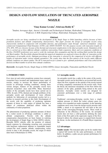
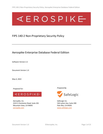
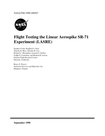
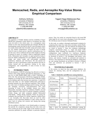
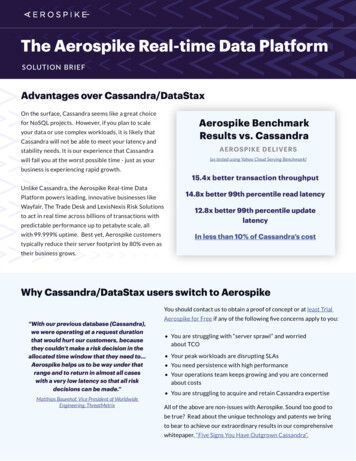
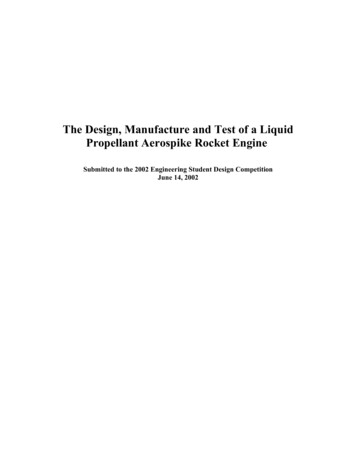
International Journal of Scientific Research & Engineering TrendsVolume 7, Issue 3, May-June-2021, ISSN (Online): 2395-566Xnozzle. Expansion process is determined by the PrandtlMeyer expansion function. From Requirements toPreliminary Design: Since the cold flow is considered, thevalues of Specific Heat Ratio (γ 1.4), gas constant ofexhaust (R 287) and chamber temperature (Ti 300K) aretaken of the values of ideal gas. For every design there hasto be minimum one parameter will be considered constantto determine the other design parameter values.measurements. And they will split faces in geometrymodel. The properties of the domain such as temperature,pressure and fluid properties need to be chosen.IV. INTRODUCTION TO CFDComputational fluid dynamics is a parameter withflexibility in nature, to show an exact results of accuracyand the measuring the applications. Then the maincategory is to be followed in 3 steps (solver, pre and postprocessor).In an modern generation it capabilities of empowersscientist and engineers they made some numericalexperiments, in a virtual flow research laboratory ( i.e.computer simulations). The fluidization is a area thatincorporate those the find in approximate results theexpression of numerical analysis relevant to the numericalcalculation of partial differential equations, it cannot becomputed precisely in the progress of physically based onmodel for those development, and the applications of theseparameters in important problem to find an fluid flow,flight dynamics and aerodynamics calculations.CFD may difficult process in that flow patterns into visionprocess in expensive or it may impossible to study usingexperimental techniques by using wind tunnels(to analysesthe flow calculations). The results of CFD simulations iscannot be completely reliable because the input parametersmay be comprise too much than appraising parameters orimprecision the mathematical model of the problem athand may be inadequate the accuracy of the results isinadequate by the available computing power .1. CFD Methods:1.1 Preprocessing: Pre-processing is define a problemand to create the geometry it's a computational domain.And moreover the preprocessing to find the moreapproach can find in to define a models, Boundaryconditions, Time scale, Domain definition, and Meshsettings. For this computational domain to generate themore number of cells for to find the accurate results.1.2 Solver: The solver deals with some governingequations in the form of incompressible flows or fluidflow equations.1.3 Post Processing: The post processing deals erpretations, Evaluation of derived values CAD Model.2. Ansys Fluent:The geometry model is created in given parameters inaerospike nozzle .The tool bodies such as surface fromsketches it may be generated in the form of someFig 1. Aerospike Nozzle.3. Mesh Region:The geometry model was generated in the form ofaerospike nozzle.Then the next process in Mesh region theAerospike nozzle was symmetrical laterally. Similarly, themesh region depends upon some conditions .Consequentlythis brings an error in CFX-Pre. A picture below shows themesh which was carried out in this analysis.Since CFD utilizes meshed as it is more commonlyreferred. The mesh has taken into the size of fine mesh.Then the mesh regions has an all set of nodes in thedomain as taken as to be in starting stage of region. In anmesh region also have some independence such asskewness and orthogonal qualities. The skewness will bein 0.85 to 0.86.Fig 2. Mesh Region.The wake formation at the end of the plug is studied. Theformation of wake at the surface of the nozzle may affectthe thrust production of the nozzle. To overcome thisproblem, the various optimized models of the sameaerospike nozzle is designed. Various models wereconsidered & compared. The Performance of Full length& optimized models were compared. 2021 IJSRET1811
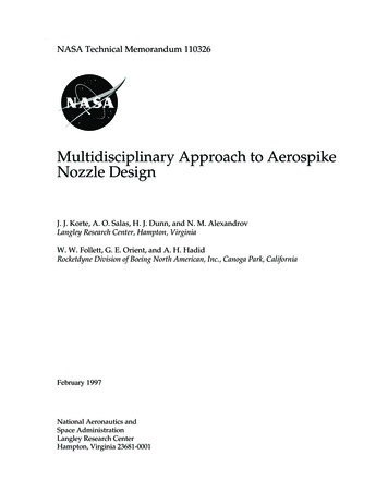
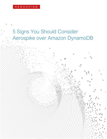
International Journal of Scientific Research & Engineering TrendsVolume 7, Issue 3, May-June-2021, ISSN (Online): 2395-566X4. CFD Setup and Solution:Table 1. CFD setup.Fig 6. 10% spike Nozzle for streamline contour.7. 20% of Spike Nozzle:5. Contours of Aerospike Nozzle:Fig 7. 20% nozzle for velocity contour.Fig 3. Full spike nozzle for velocity contour.Fig 8. 20% spike Nozzle for streamline contour.Fig 4. Full spike Nozzle for streamline contour.8. 30% of Spike Nozzle:6. 10% of Spike Nozzle:Fig 9. 30% spike nozzle for velocity contour.Fig 5. 10% spike nozzle for velocity contour. 2021 IJSRET1812
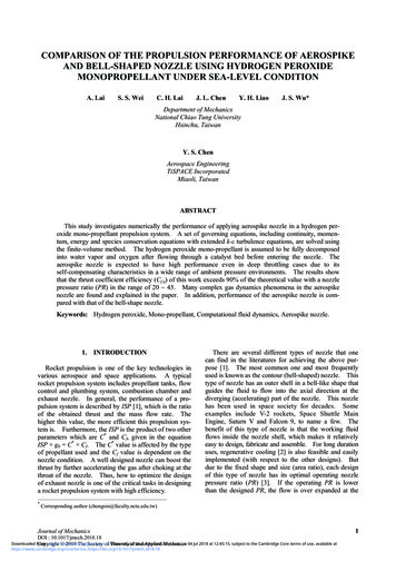
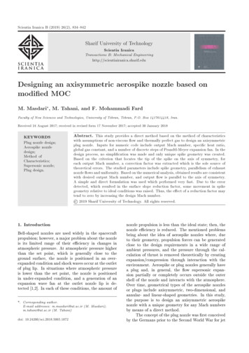
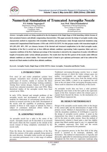
International Journal of Scientific Research & Engineering TrendsVolume 7, Issue 3, May-June-2021, ISSN (Online): 2395-566XFig 14. 50% spike Nozzle for streamline contour.Fig 10. 30% spike Nozzle for streamline contour.V. RESULTS9. 40% of Spike Nozzle:1. Tabulated Results:S.no123456Fig 11. 40% spike nozzle for velocity contour.Table 2. Calculated Results.Truncated MassThrustNozzleflow(N)rateFull spike %1.181 49726.9502. Graph For Spike Nozzle:Fig 12. 40%spike Nozzle for streamline contour.Fig 15. Graph 1: spike length vs Thrust.10. 50% of Spike Nozzle:Fig 16. Graph 2: Spike length vs Specific Impulse.Fig 13. 50% spike nozzle for velocity contour. 2021 IJSRET1813
International Journal of Scientific Research & Engineering TrendsVolume 7, Issue 3, May-June-2021, ISSN (Online): 2395-566XVI. CONCLUSIONThe 40% truncated nozzle produces only a 1.41% lesserthrust than the full-length nozzle. And comparatively thespecific impulse 10% of truncated nozzle is much lesserthan full spike nozzle. The performance of the truncatednozzle will be more effective at higher altitudes. Since, thelength of the nozzle is very less than the full-length nozzle,it produces considerable amount of performance.These findings are important when it comes to designingair and spacecraft since a nozzle with a lighter weight andequal performance is more attractive than a heavier nozzle.These nozzles need more mass flow rate, We can use thebase bleed models for high speed rocket engineapplications. The diameter of the base bleed model can bemodified based on the speed requirement. Experimentscan be done for the optimization models and comparedwith the FLUENT resultsREFERENCES[1] J. Hall, “Optimized Dual Expander AerospikeRocket”, Department of the Airforce Air UniversityAirforce Instituite of Technology, US, Ohio, (2011).[2] T. A. Ladeinde, Performance Comparison Between aFull-Length and a Truncated Aerospike Nozzle, Mscthesis Department of Mechanical and AerospaceEngineering, California State University, Long Beach,(2009).[3] M. Nazarinia, A. Naghib-Lahouti, E. Tolouei,“Design and Numerical Analysis of AerospikeNozzles with Different Plug Shapes to Compare theirPerformance with a Conventional Nozzle”, gress, Melbourne, Australia,13-17 March, (2005).[4] E. Besnard, H. Chen, T. Mueller, and J. Garvey,“Design, Manufacturing and Test of a Plug NozzleRocket Engine”, Proceedings of the 38th AIAA/ASME/SAE/ASEE Joint Propulsion Conference &Exhibit, (2002).[5] E. S. Mcvay, “Design of a Dual-Expander AerospikeNozzle Rocket Engine”, MSC Thesis, Department ofAerospace Engineering and Mechanics in theGraduate School of the University of Alabama,(2016).[6] P. Lemieux, “Development of a Reusable AerospikeNozzle for Hybrid Rocket Motors”, 39th AIAA FluidDynamics Conference, San Antonio, Texas, (2009).[7] T. Karthikeyan, S. K. Aravindhkumar, J. ArunKumar, “Design and Analysis of Aerospike NozzletoImprove Thrust in Hybrid Rocket Engine”,International Journal of Engineering Trends andTechno logy, Vol. 36, No. 7, (2016).[8] T. Niimi, H. Mori, K. Okabe, Y. M. Taniguchi,“Analyses of Flow Field Structures Around LinearType Aerospike Nozzles Using LIF and PSP”, 20thInternational Congress on Instrumentation inAerospace Simulation Facilities, ( 2003).[9] T. Wang, “Effect of Fence on Linear AerospikePlume- Induced Base-Heating Physics”, Journal ofThermo physics and Heat Transfer, Vol. 14, No. 4,(2000).[10] T. Zebbiche, Z. Youbi, “Supersonic TwoDimensionalPlug Nozzle Conception at High Temperature”,Emirates Journal for Engineering Research, Vol. 11,(2006).[11] Sergio Gomez, Francesc Moll, Antonio Rubio“Design Guidelines towards Compact Litho-FriendlyRegular cells” SPIE Photomask Technology 2012.[12] "Design for Manufacturability" http://www.me ntor.com/blogs/[13] “Litho Friendly Design kit, a tool of DFM ineers/edu Design-Kit- A-Tool-of-DFM-Strategy).[14] Y. Borodovsky, “Lithography 2009 overview ofopportunities,” in Proc.Semicon West, 2009.[15] J. A. Torres, “Layout verification in the era of processuncertainty: Target process variability bands versusactual process variability bands,” in Proc. SPIEDesign Manufacturability through Design-ProcessIntegration II, vol. 6925. 2008, pp. 692509-1–692509-8.[16] Carlson and T.-J. Liu, “Negative and iterated spacerlithography processes for low variability and ultradense integration,” in Proc. SPIE OpticalMicrolithography XXI, vol. 6924. 2008, pp. . 2021 IJSRET1814
II. AEROSPIKE NOZZLE An aerospike nozzle has a spike in the center of the nozzle. Aerospike nozzle can be described as an inverted bell nozzle where the flow expands on the outside of the nozzle instead of being completely constrained by the nozzle walls. From the throat, the innermost streamlines of the flow