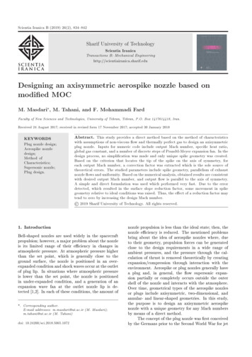
Transcription
Scientia Iranica B (2019) 26(2), 834{842Sharif University of TechnologyScientia IranicaTransactions B: Mechanical ing an axisymmetric aerospike nozzle based onmodi ed MOCM. Masdari , M. Tahani, and F. Mohammadi FardFaculty of New Sciences and Technologies, University of Tehran, Tehran, P.O. Box 1417614418, Iran.Received 24 August 2017; received in revised form 17 November 2017; accepted 30 January 2018KEYWORDSAbstract. This study provides a direct method based on the method of characteristics1. Introductionnozzle propulsion is less than the ideal state; then, thenozzle e ciency is reduced. The mentioned problemsbring about the idea of aerospike nozzles where, dueto their geometry, propulsion forces can be generatedclose to the design requirements in a wide range ofambient pressures, and the pressure through the calculation of thrust is removed theoretically by creatingexpansion/compression through interaction with theenvironment. Aerospike or plug nozzles generally havea plug and, in general, the ow supersonic expansion partially or completely occurs outside the outershell of the nozzle and interacts with the atmosphere.Over time, geometrical types of the aerospike nozzlesor plugs include axisymmetric, two-dimensional, andannular- and linear-shaped geometries. In this study,the purpose is to design an axisymmetric aerospikenozzle with a unique geometry for any Mach numbersby means of a direct method.The concept of the plug nozzle was rst conceivedby the Germans prior to the Second World War for jetPlug nozzle design;Aerospike nozzledesign;Method ofCharacteristics;Supersonic nozzle;Plug design.with assumptions of non-viscous ow and thermally perfect gas to design an axisymmetricplug nozzle. Inputs for numeric code include output Mach number, speci c heat ratio,global gas constant, and a number of discrete steps of Prandtl-Meyer expansion fan. In thedesign process, no simpli cation was made and only unique spike geometry was created.Based on the criterion that locates the tip of the spike on the axis of symmetry, foreach output Mach number, a correction factor was extracted which is the sole source oftheoretical errors. The studied parameters include spike geometry, parallelism of exhaustnozzle ows and uniformity. Based on the numerical analysis, obtained results are consistentwith desired output Mach number, and output ow is parallel to the axis of symmetry.A simple and direct formulation was used which performed very fast. Due to the errordetected, which resulted in the surface slope reduction factor, some movement in spikegeometry relative to ideal conditions was raised. Thus, the e ect of a reduction factor maytend to zero by increasing the design Mach number. 2019 Sharif University of Technology. All rights reserved.Bell-shaped nozzles are used widely in the spacecraftpropulsion; however, a major problem about the nozzleis its limited range of their e ciency in changes inatmospheric pressure. At atmospheric pressure higherthan the set point, which is generally close to theground surface, the nozzle is positioned in an overexpanded condition and shock waves occur at the outletof plug lip. In situations where atmospheric pressureis lower than the set point, the nozzle is positionedin under-expanded condition, and a generation of anexpansion wave fan at the outlet nozzle lip is detected [1,2]. In each of these conditions, the amount of*. Corresponding author.E-mail addresses: m.masdari@ut.ac.ir (M. Masdari);m.tahani@ut.ac.ir (M. Tahani)doi: 10.24200/sci.2018.5065.1072
M. Masdari et al./Scientia Iranica, Transactions B: Mechanical Engineering 26 (2019) 834{842airplane applications. Rolls-Royce, Ltd proposed theplug nozzle concept for rocket propulsion in U.S. in1950 [3]. In 1961, Rao introduced the advancement ofthe plug nozzle equipped with rocket engines where,in the study, aerospike nozzles were raised as a newdesign of types of nozzles [4]. Between 1950s and1970s, experiments were conducted on both annularand linear-shaped geometries of the aerospike nozzle atGeneral Electric and Rocketdyne that led to furtherdevelopment in plug nozzles. Later, in the 1990s,the experimental X33 SSTO program reinvigoratedan interest in the linear aerospike nozzle. Over thepast two decades, there has been a renewed interestin plug nozzles for ow physics knowledge and also indevelopment and optimization of the nozzle that led tovarious experimental studies and understanding of thenozzle performance [5-11]. The computational studiesmainly focus on validating the present-day solvers forpredicting the plug nozzle ow elds [12-15]. Majorresearchers have used designing methods for the plugnozzle in the [16-18]. In 1974, Gearold et al. [19]studied the design of maximum thrust plug nozzleswith variable inlet geometry. The results showed thatlength of the plug nozzles can be reduced to optimumlevel with the slight loss of axial thrust; the nozzles'geometry with constant length is so much dependent onbase pressure, and this parameter should be consideredto obtain a correct design and bring it closer toreality. Finally, the optimal inlet angle of the nozzleis a function of pressure and speci c heat coe cientand is highly sensitive to these two parameters [19].In a study conducted by Wuye et al. the aerospikenozzle performance and its contour optimization forsolid propellant rocket motor were investigated. Thestudy noted that thrust is reduced at the beginning ofpath according to experimental results with respect tosolid rocket motors equipped to aerospike nozzle and,then, the mentioned thrust increased with an increasein pressure behind the nozzle. This phenomenon iscommon against a variety of bell-shaped nozzles; inaddition, experimental results showed that the forceof the aerospike nozzle during ight varies in a widerange. In this regard, this study has proceeded towardsoptimization and the xing of special impulse [20].Besnard et al. conducted a study named Design, Manufacturing and Test of a Plug Nozzle Rocket Enginein 2002. Corporations of industry and university ofCalifornia state conducted the motor study. The designof the nozzle was performed by engineering estimationand, then, was investigated by CFD tool for owquality. This research indicates the ability of design,manufacturing, and experimental test of the nozzle inan academic environment [21]. Besnard and Garveyin 2004 investigated the motor applicability equippedwith aerospike nozzle in a small propellant and controlfor nano-satellite. This study highlights the priority of835using an aerospike nozzle in the rst step of a two-stagelauncher of nano satellite. The reason for the priority inthis research is explained as high amounts of availablespeci c impulse through the aerospike nozzle [22].Zebbiche and Youbi investigated a method based onthe use of the Prandtl-Meyer function of perfect gasto design the contour of a plug nozzle of arbitraryshape and speci ed exit ow conditions. Using thismethod, the condition of designed nozzles in supersonicow was compared with common bell-shaped nozzlewhose results point to optimization of the plug nozzlein terms of thrust generation [23]. Other researchers,such as Kraiko and Tillyayeva investigate the optimal contouring of two-dimensional and axisymmetricaerospike nozzles providing maximum thrust in thegiven dimensions and external pressure [24]. Wang etal. conducted a study in the eld of aerospike nozzledesign and optimization. In their study, a simpli eddesign and optimization method of aerospike nozzlecontour and the results of tests and numerical simulation of aerospike nozzles are presented. The primarynozzle contour is approximated by two circular arcsand a parabola; the plug contour is approximated by aparabola and a third-order polynomial [25]. There aremany researches that study the ow elds associatedwith truncated annular plug nozzles of varying lengthsboth experimentally and using computational tools.The ongoing investigation and identi cation of physicsof ows is of great importance among the researchesfor several reasons: the importance of the issue,unveiling of some unknown phenomena, and the needfor physical interpretations in the nozzle. Chutkey etal. investigated the analysis of annular plug nozzle oweld. Four nozzles with di erent lengths were studiedexperimentally along with computational tools. Theapplicability of RANS method and its limitations inprediction of ow in truncated spikes were studied [26].The used method for designing the aerospikenozzles similar to kinds of bell-shaped nozzles is themethod of characteristics. Rao used the commonmethod for designing an axisymmetric aerospike nozzleis developed [16]. In this method, the maximumthrust is obtained by a nozzle contour according toxed length of the nozzle and constant ambient pressure. The assumptions of the study are non-viscousand isentropic ow expansions. In this study, thevariational integral is formulated along with controlsurface in output of nozzle, and the characteristic ofow is determined in the control surface and the nozzlecontour is constructed by the method of characteristicsto meet the desired ow. The major problem of thisapproach is the assumption of a constant length ofthe nozzle, including a constant characteristic slopecontour and the complexity of the design process.Another presented method makes the nozzle contour geometry using analytical approximate conditions.
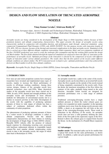
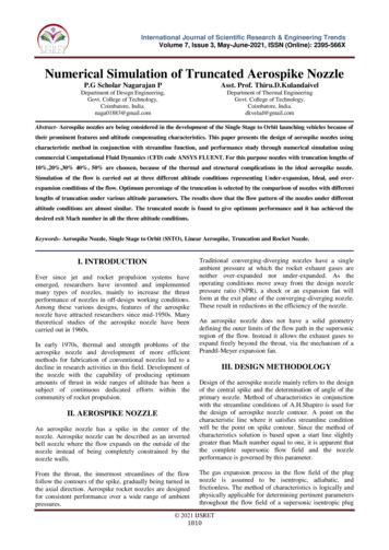
836M. Masdari et al./Scientia Iranica, Transactions B: Mechanical Engineering 26 (2019) 834{842This method was introduced by Angelino and usesan approximate method to design a plug nozzle [18].In this method, the geometry was generated approximately, and parallelism of exhaust ow vectors werenot guaranteed.The present study was carried out due to theneed for a design code for axisymmetric plug nozzledesign with the least amount of simpli cations andassumptions such as straight Mach lines and xedlength of nozzle.In this study, using the method of characteristics,a direct method is presented to design an axisymmetricaerospike nozzle contour design geometry and externalexpansion of ow with given assumptions. In thismethod, all the expansion processes of the ow occur asPrandtl-Meyer expansion waves in external wall of thenozzle and in outside lip. The initial assumptions arenon-viscous ow, thermally prefect gas, and isentropicexpansion. A gradual numerical solution method offour-order Runge-Kutta was used to capture the characteristic lines; therefore, the slope of the characteristiclines and its progress in every step can continue untilreaching the spike level point. In this method, considering the slope of the characteristic lines in every stepand using a non-linear relationship as a derivate basedon the numerical and discretional axisymmetric design,there is no errors due to considered xed slope. Errorsin the method include deviation from the thermallyprefect gas, viscous ows, Prandtl-Meyer fan as wellas the reduction factor. Compared to the methodpresented in [16], the presented method in this studyhas not considered length limitation for the nozzlesand achieved the nozzle length with the desired outputMach number. In addition, compared to the methodproposed in [18], lack of re ection characteristic linesof the surface and the output angle of the ow parallelto the axis of symmetry are considered.2. Problem explanation and governingconditionsIn the present study, initially, it is assumed that theentire process of expansion into the supersonic areaoccurs outside the nozzle body and the yield of designbelongs to spike contour of plug nozzle such that there ection of characteristic contours (Mach lines) doesnot occur. The design assumptions include thermallyprefect gas and non-viscous uid. In this conditionand in every point over spike, slope of contour mustbe equal to ow angle; thus, the nozzle spike contourwas achieved. The characteristic conditions were usedto design the axisymmetric ow. As noted earlier, thepurpose of axisymmetric aerospike nozzle design withexternal expansion of ow is to capture the nozzle spikegeometry, which should be a unique solution ideally.In Figure 1, the aerospike nozzle geometry is in two-Figure 1. Aerospike nozzle geometry in attwo-dimensional ow.Figure 2. Aerospike nozzle geometry in axisymmetricow.dimensional plane; Figure 2 shows axisymmetric geometry of the aerospike nozzle, including characteristiclines. Using [1], the characteristic and compatibilityequations are equal to Eqs. (1) and (2) as follows: drdx chr: tan ( ) ;d ( #) r pdrM21 cot (1):(2)In the above equations, the superscript sign is dedicated to both right-running and left-running characteristics. Compared to the two-dimensional plane ow,the compatibility equation is not linear and explicit;besides, the slope of characteristic lines is not constant;therefore, a numerical method is required to solve thementioned equations; to this end, in the current study,the four-order Runge-Kutta method was used.It is proven that the design of the subsonic portionof nozzle with a throat area is not very critical, andas observed, the same results in the nozzle outletwith di erent inlet geometries can be detected [3].The nozzle design in the study was carried out withcompletely external expansion, meaning that the wholeacceleration process of ow and its expansion aroundthe lip of the nozzle is done as in Prandtl-Meyer fan cocentrality. By determining input values of the speci cheat coe cient, nozzle throat length, and desired outside Mach number, the total amount of rotation of ow
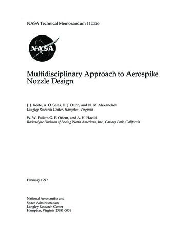
M. Masdari et al./Scientia Iranica, Transactions B: Mechanical Engineering 26 (2019) 834{842is obtained from Prandtl-Meyer function (Eq. (3)) [1]:#(M) ZpM21 dM 1 2 1 M2 M arctanarctan r pr1 (M2 1M2 1 : 11 1)(3)This value is equal to all ow rotation angles duringexpansion until reaching the desired Mach numberat the nozzle outlet. By determining the number ofcharacteristic lines, value changes of the discretizedangles of expansion fan were obtained. The results ofEq. (3) determine the angle of ow to the nozzle throat,because, at the end of expansion, the same rotationis applied to ow; nally, ow exits in parallel withthe axis of symmetry of the nozzle. Assumptions ofsolving the isentropic ow with the xed speci c heatcoe cient and Prandtl-Meyer fan are centered on thelip of the nozzle outlet.In Figures 1 and 2, AB line is the sonic characteristic line, Ai line is one of the central characteristic lineson the solution, A(i 1) line is the next characteristicline, and AC is the terminal characteristic line. TheAC in both geometries is a line with a constant slope.As mentioned, in the two-dimensional plane ow, theslope of characteristic lines is xed, and that is whyall characteristic lines on the geometry are straightlines. By measuring amount #(M) to design Machnumber from Eq. (3), the angle of the throat nozzleow (the total required angle to rotation to achieveMach number equal to 1 to the design Mach number)is obtained. First, the total required angle for rotationof ow #(M ) is discretized to small angles of d#(M ).For the two-dimensional plane geometry, the lengthof AB line can be obtained from the area of thenozzle throat, and spike geometry is obtained fromthe intersection of two lines i(i 1) and A(i 1). Inaxisymmetric geometry, the solution process becomesmore complicated. In this geometry, calculating #(M )and discretizing solution domain are similar to twodimensional plane geometry; however, given the dependence of the slope on the distance from the axis ofsymmetry from Eq. (2), the characteristic lines must bediscretized and calculated using the four-order RungeKutta and Eq. (2) must be solved in every discretizedlinear step. For axisymmetric geometry, the rst stepis the calculation of sonic line AB . In every step, thearea of formed axisymmetric is calculated, and whenthe area reaches the calculated value of the nozzlethroat, the solution stops, and the rst characteristicline is formed as an indicator of sonic line of throatAB . In this step, the ow angle value is obtained837at point B that is di erent and slightly bigger thanaxisymmetrical design and the amount of ow angle atpoint A. This is in contrast to the at two-dimensionalsolution. From this point onwards, a continuous solvingprocess leads to an unconventional geometry, because,in every step, the terminal angle on characteristicline located on spike is more relative to discretizedcentral angle at point A, and the nal point of spikeis located under the bottom of symmetry line so thatthe resulted geometry cannot be proper. To overcomethis problem, caused by physics of axisymmetric ow,a xed reduction factor of resulted terminal slope isconsidered for each point i so that, at the end of thesolution, terminal point C is placed on the axis ofsymmetry. Next, this reduction factor is determinedby increasing the amount of ow Mach number, andbecause of a reduction of characteristic line slopes ineach of terminal stations, the reduction factor becomesclose to one and spike geometry will be very close tothe ideal geometry. The impact of the coe cient is areduction in the amount of required rotation of ow onthe spike so that its impact will be dominant in creatingthe local compressive waves on the spike in practice.3. ResultsThe design code based on the MOC method wasexplained in the previous section and was carried outfor di erent supersonic Mach number plug nozzles. Thevalues of a reduction factor based on output Machnumber are shown in Table 1.The results for exit Mach numbers 1.3, 1.7, and2 were presented in ideal pressure ratio in each Machnumber, including designed spike geometry and numerical results. The obtained geometry for the mentionedMach numbers was achieved from nozzle design codeand was compared with CFD Mach contour, as shownin Figures 3, 4, and 5 showing a consistent Machdistribution between CFD and MOC. Output radiusof nozzle is considered equal to unit, and the numberof characteristic lines in the designed cases is equal toTable 1. The values of the reduction factor based onoutput Mach number.Nozzle exit ReductionMach 8880.9390.9640.974
838M. Masdari et al./Scientia Iranica, Transactions B: Mechanical Engineering 26 (2019) 834{842Figure 3. Nozzle geometry in Mach number 1.3.pected that the Mach number distribution along theaxis of symmetry of nozzle and over spike wouldincrease uniformly from a unit to setting Mach number;in the design pressure ratio, the Jet stream output exitsuniformly and is parallel to the axis of symmetry of thenozzle. Another important measure is the continuityof the slope of spike so that if there is no continuity ofcurve slope, the risk of ow separation will increase.In order to evaluate the functionality of thedesigned nozzles for each exit Mach number, thenumerical simulation in the outer diameter of the outletnozzle was taken to be 5.5 cm and in design pressureratio for each Mach number (isentropic pressure ratiofor output pressure of 1 atm.). Numerical simulationparameters are given in Table 2.Using Figures 6, 7, and 8 and comparing theresulting Mach contours of nozzle both resulted in adesign code and a numerical solution for the idealpressure ratio of nozzle; in addition, good consistencewas observed between Mach number distributions inFigure 4. Nozzle geometry in Mach number 1.7.Figure 6. Distribution of Mach number resulted innumerical analysis in exit Mach 1.3.Figure 5. Nozzle geometry in Mach number 2.200 lines where, due to the discretizing solution forevery characteristic with discretized distance of about0.001, these lines are created as curves at the throatof nozzle, and terminal characteristic line is created asa line with a constant slope because zero ow angle iszero at outlet in Eq. (2). As mentioned earlier, thereis no limitation apart from assumptions of non-viscousow and thermally prefect gas in the design process.According to the design requirements, it is ex-Figure 7. Distribution of Mach number resulted innumerical analysis in exit Mach 1.7.
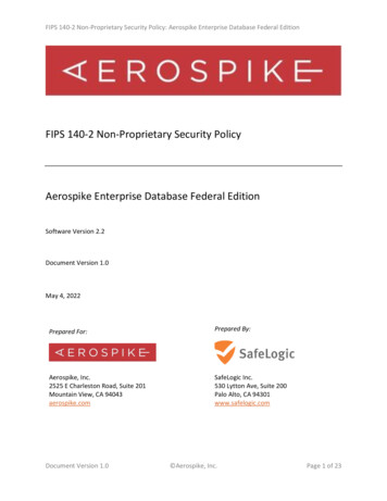
M. Masdari et al./Scientia Iranica, Transactions B: Mechanical Engineering 26 (2019) 834{842839Table 2. Numerical simulation parameters.Physical parameterType/modelNumber of cells in studied networkY CriteriaTurbulenceSolverAnalysis conditionDensitySpeci c heat coe cientViscositySolving formulationType uxSolving orderCourse: 29000 medium: 252500 ne: 100500Y 1K-omega, SSTDensity basedAxisymmetric, steadyIdeal gasPiecewise polynomialSutherland 3 coe cient methodImplicitAUSMSecond orderFigure 9. Distribution of outlet angle at exit nozzleFigure 8. Distribution of Mach number resulted inleading to the tip of the spike for Mach numbers 1.3, 1.7and 2.0.the spike. The Mach number in the last characteristicline was consistent with designed Mach numbers foreach nozzle.Another important parameter in the aerospikenozzle is the parallelism of ow to the axis of the nozzleand the uniformity of the outlet angle of the nozzle intothe ideal pressure ratio of the nozzle. If the ow is notparallel, the thrust vector has a lateral component andthe e ciency of Nozzle reduces. Figure 9 shows thedistribution of outlet angle at exit nozzle leading tothe tip of the spike. The range of changes of angleon the negative side is of maximum 0.01 degrees and,at best, it is 0.003 degrees, which is quite perfect.These deviations are higher when the nozzle operatesin higher or lower ambient pressure. The minimalamount of exit ow angle deviation at the nozzle outletrepresents the validity of functional design of nozzlegeometry at designed atmospheric pressure and enablesthe nozzle to generate maximum thrust by exhaustingow parallel to the axis of symmetry.Another important parameter in the design of theaerospike nozzle is continuity of spike curve; if it meetsits criteria, the risk of ow separation may reduce,because, in the supersonic ow, lack of continuitymay cause a sudden change of a slope of surface andmake local compressive waves. Figure 10 shows thedistribution of spike curve slope along the axis ofsymmetry. Using the gure, it is known that thereare established continuity conditions for each point ofspike (there are no sharp edge or breaks in the curve).The last parameter evaluated in this study is thenozzle e ciency using a number of analytical data. Thee ciency of a nozzle was achieved by Eq. (4) [2]:actual exit velocit y2:(4) Nozzle ideal exit velocit y2For a designed nozzle contour, the amount of thrust ofnozzle and the e ciency in design condition are shownin Table 3.Finally, Figure 11 shows a comparison among thepro les of designed nozzles in the presented methodnumerical analysis in exit Mach 2.
840M. Masdari et al./Scientia Iranica, Transactions B: Mechanical Engineering 26 (2019) 834{842Figure 10. Distribution of slope of spike curve for Machnumbers 1.3, 1.7, and 2.0.Mach number 1.3 from [18] and suggested method 1 4.Figure 11. Comparison among spike contours in designMach number 2.89 from [16,18] and suggested method 1 23.Table 3. Thrust and e ciency for designed nozzles.Nozzle exit Thrust E ciencyMach number(N)(%)1.31.72.0Figure 12. Comparison among spike contours in design547.11929.971287.2199.396.796.7and other resources associated with aerospike nozzle.According to this gure, the contour resulted in thesuggested method has more compliance with analyticalmethod presented in [18]; however, in the input region,a minor di erence can be seen. This means that theproposed method in [18] predicts more input area. Dueto the form of the method, the mentioned reference isused through estimating method by analytical equations and does not use the method of characteristics;besides, there is no analysis of these di erences. Thevalue of the di erence in less Mach numbers wasobserved better (Figure 12). Compared with themethod presented in [16], there are many di erences.Firstly, due to di erences in calculation methods, spikecuts o , and considering the slope of characteristic linesas constant makes the characteristic lines longer thantrue state; thus, leaner spike is obtained as comparedto the other two methods; in addition, the inlet area ofow is also predicted to be more than true value.The e ect of viscosity virtually makes the spikethicker than the ideal condition and can be determinedas displacement thickness in each station on spike.Two-phase ow, which occurs in solid propellant rockets, changes the speci c heat ratio, and density of owcan be considered using CFD results in MOC output,in which both of mentioned deviations are out of scopeof this study.4. ConclusionThe current study introduced the design method ofthe aerospike nozzle while assuming a non-viscous ow,thermally prefect gas without any limitation and certain error sources; in particular, based on the MethodOf Characteristics (MOC), three nozzles geometries forMach numbers 1.3, 1.7, and 2.0 were designed throughthe numerical code formulation. The introducedmethod has the capability to create geometry in thedesired exit Mach for each type of operating gas in verysimple and low computational cost. In this method,to create a concave and at geometry for spike andalso to reach the tip of the spike to the symmetry line,a reduction factor for terminal angle was obtained onthe surface of spike for each Mach number so that, byincreasing the exit Mach number, due to the reductionof slope of each characteristic line and widening ofexpansion fan in the nozzle cowl, the reduction factorused for the terminal angle is close to number 1 and,thus, the resulting error can be removed. Due tothe reduction of spike angle in non-ideal conditions,
M. Masdari et al./Scientia Iranica, Transactions B: Mechanical Engineering 26 (2019) 834{842this factor creates poor local density waves on the lowdesign Mach numbers. To validate the design code fornozzles, three 2-D axisymmetric numerical simulationswere performed for the given Mach numbers 1.3, 1.7,and 2.0, where the constant output diameter of nozzleis equal to 55 mm and certain isentropic ratio ofdesign for creating output pressure is equal to 1. Theresults included Mach number distribution, the outputangle parallel to the axis of symmetry, and the createdthrusts which all represent very good consistency withthe results of analysis and numerical code developedfor nozzle design. In addition, the investigation ofthe slope of the spike indicates the continuity of spikecurve in order to prevent the ow separation risk. Twocommon methods for aerospike nozzle design in [16,18]were proposed. A comparison of the proposed methodin the current study with those mentioned in referenceswas conducted. In comparison with the [16], dueto xed slope of the characteristic lines, deviationfrom actual conditions, and xed nozzle length in thismethod, the presented method in this study is moreconsistent with the real condition; moreover, there is nolimitation in nozzle length. In addition, in the methodintroduced in [18], there is considerable overlapping inresults; however, the prediction of the area of inlet inthis reference is not appropriately accurate, and it isan area greater than the actual value.Nomenclaturerx MDistance from axis of symmetryAxial distanceFlow velocity angle from axis ofsymmetryCharacteristic line angle from axis ofsymmetryPrandtl-Meyer functionMach numberHeat capacity ratioReferences1. Anderson, J.D., Modern Compressible Flow, 3rd Edn.,pp. 397-407, McGraw-Hill, New York, USA (1990).2. Faro, I.D.V., Handbook of Supersonic Aerodynamics,1st Edn., Johns Hopkins university press, USA (1964).3. Gri th, A. and Rolls-Royce., Jet Propulsion Nozzle,Patent, Docket No. US 2928235 A, USA (1954).4. Rao, G.V.R. \Recent developments in rocket nozzlecon gurations", ARS Journal, 31(11), pp. 1488-1494(1961).5. Tomita, T., Tamura, H., and Takahashi, M. \Anexperimental evaluation of plug nozzle ow elds",32nd Propulsion Conference and Exhibit, Lake BuenaVista (1996).8416. Tomita, T., Takahashi, M., Onodera, T., andTamura, H. \Visualization of shock wave interaction on the surface of aerospike nozzles", 34thAIAA/ASME/SAE/ASEE Joint Propulsion Conference and Exhibit, OH (1998).7. Vuillamy, D., Duthoit, V., and Berry, W. \European investigation of clustered plug nozzles", 35thJoint Propulsion Conference and Exhibit, Los Angeles(1999).8. Sule, W.P. and Mueller, T.J. \Annular truncated plugnozzle ow eld and base pressure characteristics",Journal of Spacecraft and Rockets, 10(11), pp. 689-695(1973).9. Kapilavai, D., Tapee, J., Sullivan, J., Merkle, C.L.,Wayman, T.R., and Conners, T.R. \Experimentaltesting and numerical simulations of shrouded plugnozzle ow elds", 45th AIAA/ASME/SAE/ASEEJoint Propulsion Conference & Exhibit, Denver (2009).10. Junwei, L., Yu, L., Unfei, L., Changhui, Yibai,W., and Ningfei, W. \Experimental and numerical study on two dimensional plug nozzle", 46thAIAA/ASME/SAE/ASEE Joint Propulsion Conference & Exhibit, Nashville (2010).11. Tomita, T., Takahashi, M., and Tamura, H. \Floweld of clustered plug nozzles", 33rd Joint PropulsionConference and Exhibit, WA (1997).12. Chutkey, K., Vasudevan, B., and Balakrishnan, N.\Flow eld analysis of linear plug nozzle", Journal ofSpacecrafts and Rockets, 49(6), pp. 1109-1119 (2012).13. Ito, T., Fujii, K., and Hayashi, A.K. \Computations ofthe axisymmetric plug nozzle ow elds: Flow structures and thrust performance", Journal of Propulsionand Power, 18(2), pp. 254-260 (2002).14. Rommel, T., Hagemann, G., Schley, C.A., Kr ulle,G., and Manski, D. \Plug nozzle ow eld analysis",Journal of Propulsion and Power, 13(5), pp. 629-634(1997).15. Ruf, J.H. and McConnaughey, P. \A numerical analysis of a three dimensional aerospike", 33rd JointPropulsion Conference and Exhibit, Huntsville (1997).16. Rao, G.V.R. \Spike nozzle contour for optimumthrust", Journal of Planetary and Space Science, 4,pp. 92-101 (1961).17. Greer, H. \Rapid method
with aerospike nozzle in a small propellant and control for nano-satellite. This study highlights the priority of using an aerospike nozzle in the rst step of a two-stage launcher of nano satellite. The reason for the priority in this research is explained as high amounts of available speci c impulse through the aerospike nozzle [22].