Transcription
NASA/TM-1998-206567Flight Testing the Linear Aerospike SR-71Experiment (LASRE)Stephen Corda, Bradford A. Neal,Timothy R. Moes, Timothy H. Cox,Richard C. Monaghan, Leonard S. Voelker,Griffin P. Corpening, and Richard R. LarsonDryden Flight Research CenterEdwards, CaliforniaBruce G. PowersAnalytical Services and Materials, Inc.Hampton, VirginiaSeptember 1998
The NASA STI Program Office . . . in ProfileSince its founding, NASA has been dedicatedto the advancement of aeronautics and spacescience. The NASA Scientific and TechnicalInformation (STI) Program Office plays a keypart in helping NASA maintain thisimportant role.The NASA STI Program Office is operated byLangley Research Center, the lead center forNASA’s scientific and technical information.The NASA STI Program Office provides accessto the NASA STI Database, the largest collectionof aeronautical and space science STI in theworld. The Program Office is also NASA’sinstitutional mechanism for disseminating theresults of its research and development activities.These results are published by NASA in theNASA STI Report Series, which includes thefollowing report types: TECHNICAL PUBLICATION. Reports ofcompleted research or a major significantphase of research that present the results ofNASA programs and include extensive dataor theoretical analysis. Includes compilationsof significant scientific and technical dataand information deemed to be of continuingreference value. NASA’s counterpart ofpeer-reviewed formal professional papers buthas less stringent limitations on manuscriptlength and extent of graphic presentations.TECHNICAL MEMORANDUM. Scientificand technical findings that are preliminary orof specialized interest, e.g., quick releasereports, working papers, and bibliographiesthat contain minimal annotation. Does notcontain extensive analysis.CONTRACTOR REPORT. Scientific andtechnical findings by NASA-sponsoredcontractors and grantees. CONFERENCE PUBLICATION.Collected papers from scientific andtechnical conferences, symposia, seminars,or other meetings sponsored or cosponsoredby NASA. SPECIAL PUBLICATION. Scientific,technical, or historical information fromNASA programs, projects, and mission,often concerned with subjects havingsubstantial public interest. TECHNICAL TRANSLATION. Englishlanguage translations of foreign scientificand technical material pertinent toNASA’s mission.Specialized services that complement the STIProgram Office’s diverse offerings includecreating custom thesauri, building customizeddatabases, organizing and publishing researchresults . . . even providing videos.For more information about the NASA STIProgram Office, see the following: Access the NASA STI Program Home Pageat http://www.sti.nasa.gov E-mail your question via the Internet tohelp@sti.nasa.gov Fax your question to the NASA Access HelpDesk at (301) 621-0134 Telephone the NASA Access Help Desk at(301) 621-0390 Write to:NASA Access Help DeskNASA Center for AeroSpace Information7121 Standard DriveHanover, MD 21076-1320
NASA/TM-1998-206567Flight Testing the Linear Aerospike SR-71Experiment (LASRE)Stephen Corda, Bradford A. Neal,Timothy R. Moes, Timothy H. Cox,Richard C. Monaghan, Leonard S. Voelker,Griffin P. Corpening, and Richard R. LarsonDryden Flight Research CenterEdwards, CaliforniaBruce G. PowersAnalytical Services and Materials, Inc.Hampton, VirginiaNational Aeronautics andSpace AdministrationDryden Flight Research CenterEdwards, California 93523-0273September 1998
NOTICEUse of trade names or names of manufacturers in this document does not constitute an official endorsementof such products or manufacturers, either expressed or implied, by the National Aeronautics andSpace Administration.Available from the following:NASA Center for AeroSpace Information (CASI)7121 Standard DriveHanover, MD 21076-1320(301) 621-0390National Technical Information Service (NTIS)5285 Port Royal RoadSpringfield, VA 22161-2171(703) 487-4650
FLIGHT TESTING THE LINEAR AEROSPIKESR-71 EXPERIMENT (LASRE)Stephen Corda,* Bradford A. Neal,† Timothy R. Moes,‡ Timothy H. Cox,§ Richard C. Monaghan,¶Leonard S. Voelker,# Griffin P. Corpening,** and Richard R. Larson††NASA Dryden Flight Research CenterEdwards, CABruce G. Powers‡‡Analytical Services and Materials, Inc.Hampton, VirginiaAbstractThe design of the next generation of space accessvehicles has led to a unique flight test that blends thespace and flight research worlds. The new space vehicledesigns, such as the X-33 vehicle and Reusable LaunchVehicle (RLV), are powered by linear aerospike rocketengines. Conceived of in the 1960’s, these aerospikeengines have yet to be flown, and many questionsremain regarding aerospike engine performance andefficiency in flight. To provide some of these data beforeflying on the X-33 vehicle and the RLV, a spacecraftrocket engine has been flight-tested atop the NASASR-71 aircraft as the Linear Aerospike SR-71Experiment (LASRE). A 20 percent–scale, semispanmodel of the X-33 vehicle, the aerospike engine, and allthe required fuel and oxidizer tanks and propellant feedsystems have been mounted atop the SR-71 airplane forthis experiment. A major technical objective of theLASRE flight test is to obtain installed-engineperformance flight data for comparison to wind-tunnel*Stephen Corda, Aerospace Engineer, Propulsion and PerformanceBranch, (805) 258-2103, stephen.corda@dfrc.nasa.gov†Bradford A. Neal, Aerospace Engineer, Operations EngineeringBranch, (805) 258-3204, brad.neal@dfrc.nasa.gov‡Timothy R. Moes, Aerospace Engineer, Aerodynamics Branch,(805) 258-3054, tim.moes@dfrc.nasa.gov§Timothy H. Cox, Aerospace Engineer, Controls Branch,(805) 258-2126, tim.cox@dfrc.nasa.gov¶Richard C. Monaghan, Aerospace Engineer, AerostructuresBranch, (805) 258-3842, richard.monaghan@dfrc.nasa.gov#Leonard S. Voelker, Aerospace Engineer, Structural DynamicsGroup, (805) 258-3709, len.voelker@dfrc.nasa.gov**Griffin P. Corpening, Aerospace Engineer, Propulsion and Performance Branch, (805) 258-2497, griff.corpening@dfrc.nasa.gov††Richard R. Larson, Aerospace Engineer, Systems EngineeringBranch, (805) 258-3740, dick.larson@dfrc.nasa.gov‡‡Bruce G. Powers, Aerospace Engineer, Analytical Services andMaterials, Inc., (805) 258-3732, bruce.powers@dfrc.nasa.govThis paper is declared a work of the U. S. Government and is notsubject to copyright protection in the United States.results and for the development of computational fluiddynamics–based design methodologies. The ultimategoal of firing the aerospike rocket engine in flight is stillforthcoming. An extensive design and developmentphase of the experiment hardware has been completed,including approximately 40 ground tests. Five flights ofthe LASRE and firing the rocket engine using inertliquid nitrogen and helium in place of liquid oxygen andhydrogen have been successfully completed.NomenclatureGH2gaseous hydrogenH2OwaterHeheliumKEASequivalent airspeed, knotsLASRELinear Aerospike SR-71 ExperimentLN2liquid nitrogenLO2liquid oxygenO2oxygenPCMpulse code modulatorRLVReusable Launch VehicleSMARTsignal management for analysis in real timeTEA–TEB Triethyl aluminum–triethyl boraneUSAFUnited States Air ForceIntroductionThe Linear Aerospike SR-71 Experiment (LASRE)(fig. 1)1 began during the competition to build the X-33vehicle, a subscale, suborbital, rocket technologydemonstrator vehicle for the planned single-stageto-orbit, rocket-powered Reusable Launch Vehicle(RLV). The LASRE is a flight-test contribution to the
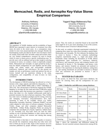
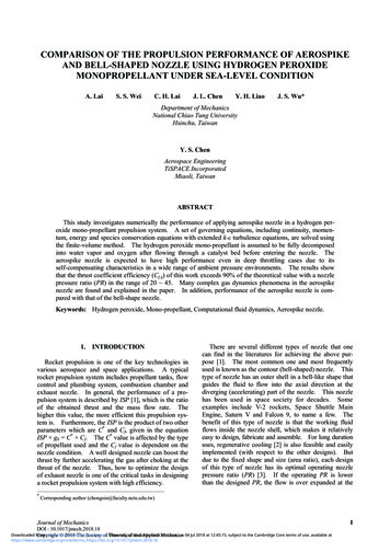
The Aerospike Rocket EngineA natural synergism exists between this lifting-bodyshape and a rocket engine configuration called the linearaerospike, first developed in the 1960’s.2–4 Therectangular nozzles of the linear aerospike engine easilyintegrate into the rectangular base of the lifting body. Anaerodynamic advantage is realized because theaerospike engines fill in much of the lifting-body base.Theoretically, a major advantage of the aerospikerocket engine is the ability of the nozzle to adjust withaltitude changes to the free-stream static pressure,which results in a higher specific impulse than aconventional bell nozzle has at low altitudes (fig. 3).5–7This altitude compensation is caused by the uniquenozzle geometry of the aerospike engine, which has acentral ramp terminating in either a plug base or spike inthe center and is scarfed, or open, to the atmosphere onthe sides.EC97-44295-108Figure 1. The LASRE in flight.Lockheed Martin Skunk Works (Palmdale, California)X-33 proposal. Lockheed Martin subsequently won theX-33 competition with a design that utilizes a flat,triangular planform, lifting-body shape (fig. 2) similarto lifting-body designs that had been tested and flown atEdwards Air Force Base (California) prior todevelopment of the current Space Shuttle. Use of tradenames or names of manufacturers in this document doesnot constitute an official endorsement of such productsor manufacturers, either expressed or implied, by theNational Aeronautics and Space Administration.The term “aerospike” derives from the fact that thecentral spike need not be a real, solid surface; the spikecan be aerodynamically formed by injecting gases fromthe engine base. The nozzle exhaust flow is free toexpand on the open sides and self-adjust to staticpressure changes with altitude. This automatic altitudecompensation of the exhaust gases allows the nozzle torun at more optimum conditions than a conventionalfixed-geometry, bell-type nozzle, which is designed tobe optimum for only one altitude. The aerospike enginecan also be built from individual thruster segments thatcan be turned on and off to provide thrust vectoring tosteer the X-33 vehicle, rather than using the heavier,conventional technique of gimbaling, or moving, anentire rocket bell nozzle.The aerospike concept is not new, and althoughseveral large-scale ground tests of the aerospike enginewere conducted in the 1970’s, no flight data had everbeen collected. Ground testing provided only a sea-leveldata point for the ability of the aerospike nozzle tocompensate and adjust to altitude. The questionremained as to whether the aerospike nozzle wouldreally compensate for altitude during the rocket ascentand provide better performance. One method to answerthis question is to test the aerospike engine in a windtunnel, which has been done to a limited extent. Thesewind-tunnel tests involved flowing inert, “cold” gasesthrough the aerospike rocket engine; the rocket enginewas not actually fired using combustible fuels. Althoughthese “cold-jet” tests did provide some importantaltitude compensation data, the missing piece of data isthe performance of the aerospike rocket nozzle atED97-43938Figure 2. The X-33 and RLV spacecraft with aerospikerocket engines.2
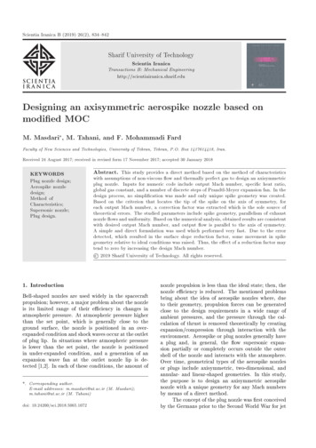
AerospikenozzleSpecificimpulseBellnozzleBell nozzleSea levelAerospike nozzleHigh altitudeAltitude960227Figure 3. Comparison of flow through conventional bell nozzle and aerospike nozzle.Experiment Flight Test Objectivesvarying altitudes with a “hot plume” (for instance, hot,combusting gases flowing through the nozzle andinteracting with the free-stream air).The LASRE flight test used a linear aerospike rocketengine mounted in a 20 percent–scale, semispan,X-33–type vehicle. The linear aerospike rocket enginehas eight linear, single-thruster-combustor segments(four on each side of the engine) fueled by gaseoushydrogen and liquid oxygen. The major technicalobjectives were to measure the performance of theinstalled aerospike rocket engine along therepresentative RLV trajectory, demonstrate theoperation of the aerospike rocket engine in arepresentative flight environment, and support thedevelopment of a computational fluid dynamics–baseddesign methodology for integration of the linearaerospike rocket engine in lifting-body configurations.This flight test also provided a unique opportunity togain experience with the blending of airplane and spacevehicle design, operations, research, and testcommunities.Another way to obtain aerospike engine test data is toactually fly an aerospike rocket engine and fire it inflight at various altitudes. The NASA Dryden FlightResearch Center (Edwards, California) had alreadyperformed design work on a proposed external burningexperiment that had many of the salient featuresrequired to consider flight test of an aerospike rocketengine on an airplane. NASA Dryden and LockheedMartin Skunk Works had been working on a flight test,in support of the National Aerospace Plane (NASP)program, that would externally burn hydrogen on a largeplate mounted atop the Mach-3 SR-71 aircraft. Thisdesign work, coupled with the existing SR-71 legacy ofcarrying large external payloads such as the D-21 drone,helped increase the feasibility of flying the aerospikeengine on the SR-71 airplane. Also, the proposed X-33ascent trajectory fit within the SR-71 flight envelope to amaximum altitude of approximately 80,000 ft (fig. 4).The Flight Test TeamThe LASRE team is composed of Lockheed MartinSkunk Works; Lockheed Martin Astronautics (Denver,Colorado); Boeing North American/RocketdyneDivision (Canoga Park, California); the U. S. Air Force(USAF) Research Laboratory (formerly the USAFPhillips Laboratory) (Edwards, California); the NASAMarshall Space Flight Center (Huntsville, Alabama);and NASA Dryden. Lockheed Martin Skunk Works wasresponsible for the design, fabrication, and integrationof the LASRE structural hardware and SR-71 aircraftThis paper details the LASRE flight-test evolutionfrom early configuration development, ground and flightcheckouts, and flight test planning and preparation toflight testing. Sample flight test results and analysis arepresented in the areas of stability and control, transonicperformance, structural loads, structural dynamics, andpropellant feed system and aerospike rocket engineperformance. Some lessons learned in conducting acomplex and hazardous flight test are also presented.3
90 x esentativeRLV trajectory3020Planned hot-fireflight test point100.51.01.52.0Mach number2.53.03.5980457Figure 4. The SR-71 flight envelope with LASRE hot-fire test points.has two SR-71 aircraft on loan from the USAF andoperates them as flight research aircraft. The SR-71aircraft has a rather narrow flight envelope with amaximum cruise performance of approximatelyMach 3.2 at altitudes higher than 80,000 ft (fig. 4). TheSR-71 aircraft has titanium construction and is paintedblack to operate at the high temperatures associatedwith Mach-3 flight (hence its designation as the“Blackbird”).modifications. Lockheed Martin Astronautics wasresponsible for the design and fabrication of thepropellant feed systems for the rocket engine.Rocketdyne designed and fabricated the linear aerospikerocket engine. The USAF provided their ResearchLaboratory test facility and technical support for theground tests. NASA Marshall provided technicalexpertise for liquid propulsion testing and operations.NASA Dryden provided overall technical support and isthe flight test lead.The SR-71 “A” model used in this test has a tandem,two-place cockpit configuration with flight controls inthe forward cockpit. The aft cockpit is occupied by aflight test engineer who operates the aerospike enginecontrols and emergency systems in addition toperforming normal radio and navigation duties.In addition to the technical challenges, the LASREflight test was new and unique in another way. This testwas the first to be conducted under a new way of doingbusiness for NASA—using the government and industry“cooperative agreement.” Under this arrangement, thetraditional role of government-dictated requirementsand industry-supplied deliverables is replaced by acooperative structure in which government and industryshare the responsibilities, costs, and risks of theendeavor. Without understatement, this sharedresponsibility was one of the more challenging aspectsof this test, especially considering the very differentphilosophies of the various teammates regarding designmethods, test techniques, and risk management.SR-71 Description and ModificationsModifying the SR-71 airplane to carry the LASRE(fig. 5) and fulfill its role as a true research platform wasnecessary. Modifications were made to the aircraftstructure, flight test instrumentation, the aircraft fuelsystem, and the aircraft propulsion system.Structural modifications included strengthening thefuselage and installing attachment hardware to carry theLASRE. The experiment is structurally attached to thetop of the fuselage at a single self-aligning ball and attwo vertical links and one lateral link. This attachmentExperiment DescriptionThe aircraft used to carry the aerospike experiment isthe Lockheed-built SR-71 “Blackbird” aircraft. NASA4
17.327.50Reflection 0107.40980458Figure 5. The LASRE pod mounted atop the SR-71 aircraft.experiment.8 The engines were “tuned up” to operate atthe top of their performance capability by adjusting thefuel flow, revolutions/min, and exhaust gas temperature.This thrust enhancement was gained at the cost ofslightly reduced engine life and more frequentinspections of the engines.does not affect the normal load paths or stiffness of thebasic SR-71 aircraft. The concentrated load points at theattachments required local reinforcement internal to thefuselage to distribute flight loads into the SR-71airframe. All new structure and existing modifiedstructure used a factor of safety 50 percent greater thanthe normal aircraft factor of safety to eliminate the needfor structural testing. When LASRE flight testing iscompleted, the fittings at the three external attachmentpoints can be easily removed. All the internal structuralreinforcements will remain. The reinforced areas willnot affect normal SR-71 operations and could be usedfor future programs.Linear Aerospike SR-71 Experiment HardwareThe LASRE flight test hardware is composed of fourelements identified as the “canoe,” the “kayak,” the“reflection plane,” and the “model” (fig. 6). Thecomplete assembly of this hardware is designated the“pod.” The pod is approximately 41.0 ft long andapproximately 7.5 ft tall at its highest point, the top ofthe model. The pod is constructed of common,low-carbon steel and has a total design weight of14,500 lbm, including the consumables for theexperiment. The pod structure was designed with anadditional 50-percent factor of safety over normalaircraft structural requirements to eliminate the need forstructural ground and flight testing. As previouslymentioned, the pod is mounted between the twin verticalrudders of the SR-71 airplane at three hard points on theSR-71 fuselage (fig. 5). The pod is designed to remainattached to the SR-71 airplane and cannot be jettisonedor released in flight.Plumbing was also installed to supply gaseousnitrogen from the SR-71 airplane to the experiment forpurging. The SR-71 aircraft has several liquidnitrogen–filled Dewar flasks that normally supplygaseous nitrogen to pressurize and make inert theaircraft fuel tanks as the fuel is consumed. Two of theseDewar flasks supply nitrogen gas to purge the inside ofthe LASRE of oxygen to help mitigate the possibility offire or explosion in the event of a leak of the hydrogengas used to fuel the rocket engine.Aircraft propulsion modifications involved installingtwo thrust-enhanced Pratt & Whitney (West PalmBeach, Florida) J58 turbojet engines to provide anapproximately 5-percent increase in thrust to helpovercome the increased drag of the LASREThe canoe is a long, fairing-like structure mounteddirectly to the SR-71 upper fuselage. The canoe houses5
within the pod. The aerospike rocket engine is mountedin the aft end of the model. A hypergolic combination oftriethyl aluminum and triethyl borane (TEA–TEB) isused as an ignitor for the rocket, igniting on contact withoxygen. The model is mounted on a force balance thatpermits the measurement of in-flight forces.five gaseous hydrogen fuel tanks storing a maximum of27 lbm of gaseous hydrogen at 6,000 lbf/in2, twocooling water tanks, and three 10,000–lbf/in2 heliumpressurization tanks (fig.7). Water is used to internallycool the rocket engine. The kayak is a structure abovethe canoe that sets the incidence angle of the model. Thereflection plane is a flat plate that is mounted atop thekayak. The model is a one-half-span lifting-body shape,representative of an X-33–type lifting body, mounted onthe reflection plane. Within the model rests the liquidoxygen tank storing a maximum of 335 lbm of liquidoxygen, and two additional 10,000–lbf/in2 heliumpressurization tanks.The design challenge of the LASRE propellant feedsystem is fairly unique. Although the system is notrepresentative of an actual main propulsion rocketsystem, it does have to meet the safety requirementsassociated with being mounted in a piloted airplane.Although the feed system is similar to a ground facilitysystem, it is constrained in volume and weight. Thevolume limitation is dictated by the maximum allowablecross-sectional area that the SR-71 aircraft can carryOne major safety concern was the very high–pressuregases and combustible gases and liquids contained17.32 ftReflectionplane7.50 ft2.50 ftAerospikerocket engineModelKayakCanoe7.53 ft1.86 ft41.21 ft2.75 ft980459Figure 6. The LASRE pod.LO2 ventBalanceHeModelCanoeHe He HePod cooling H2OHeKayakEngine cooling onplaneH2O exitGH2 dumpSR-71Purge LN2980204Figure 7. The LASRE pod internal arrangement.6
through the high-drag transonic Mach region. Theweight constraint is dictated by aircraft performancerequirements. Therefore, the amount of each of theconsumable commodities is limited. In addition to thephysical constraints of the system, intense schedulerequirements existed early in the program. To meet theschedule, every effort was made to use off-the-shelfhardware and minimize development costs andcomponent-level testing.A control panel in the aft cockpit of the SR-71airplane is used to initiate the controller sequences thatfire the rocket motor and safeguard the systems. The aftcockpit control panel also allows the aircrew to monitorcritical propellant feed system health parameters, suchas tank pressures and temperatures. A backup,emergency control system also exists, independent ofthe LASRE controller, that enables the aircrew to dumpand make inert the hydrogen tanks and vent the pressurein the liquid oxygen tank. The normal test sequenceconsists of a single 3-sec firing of the rocket enginefollowed by independent dumping of the remaininghydrogen, liquid oxygen, and water.Buried inside the pod are the tankage, plumbing,valves, instrumentation, and controllers required tooperate the aerospike rocket engine, making the systemessentially self-contained (fig. 7). The LASREpropellant feed system is a pressure-fed system thatsupplies gaseous hydrogen fuel and liquid oxygen to theaerospike rocket engine. §§In addition to being used as apurging gas, high-pressure gaseous helium is used as apressurant to move the oxidizer and cooling water.Figure 9 shows the LASRE system controllerarchitecture. The pod systems are commanded by themain controller, which receives inputs from theinstrumentation system and the cockpit control panel.An unusual feature of this architecture is that theexperiment or research instrumentation andsafety-of-flight instrumentation are on a commonsystem. Typically, the safety-of-flight instrumentationsystem is independent of the research instrumentationsystem to avoid losing safety-of-flight information if theresearch instrumentation fails, which would have meantan unacceptable increase in the size of either theinstrumentation system or main controller for theLASRE system. Because the main controller wasdesigned to be fail-safe (as explained below), separatingthe research and safety-of-flight instrumentationsystems was not considered necessary. Controlcommands for the hydrogen, liquid oxygen, and watersystem main valves are sent to a controller that operatesthe valves. Health and status words are also returned tothe main controller.Oxygen sensors were installed in the pod to verifythat the nitrogen purge is maintaining the oxygen levelat less than 4 percent in flight, the low combustion limitfor a hydrogen and oxygen mixture. Note that, similarly,installation of hydrogen sensors was planned fordetection of hydrogen leaks. Unfortunately, efforts toflight-qualify an existing hydrogen detection systemwere unsuccessful.The aerospike rocket engine is composed of eightsingle-thruster units, four on each side of the engine(fig 8). The engine is made primarily from copper andcopper alloys and is internally water-cooled. The engineis not an X-33 flight weight design, but rather a“boilerplate” design. Each thruster is designed tooperate at a relatively low combustor pressure ofapproximately 200 lbf/in2, providing a total thrust ofapproximately 5500 lbf. A 0.3 inch–thick layer ofsilicone ablative protects the reflection plane from theimpingement of the rocket engine exhaust. This materialdegrades with use but is intended to last the life of thetest program.The system was designed to be fail-safe, which meansthat for any first failure detected by the main controller,the system is shut down in an orderly fashion and entersa safe, “abort” mode. Status words issued by the maincontroller identify the cause of the failure and are readin real time by special monitoring software anddisplayed in the mission control center during the flighttest. This monitor, called signal management foranalysis in real time (SMART), works by executing aknowledge base of Boolean expressions, called rules, ata speed of 100 Hz. When the rules evaluate and verifynominal function of the LASRE system, texturalmessages are generated with a time tag and shown on amission control center display. Rules are developed toassist in determining expected prefiring conditions forthe rocket engine, postfiring information, and latchingfor any failure aborts. A message log file is alsogenerated and written to a computer hard disk.The LASRE is controlled using a single-channelcomputer, called the main controller, that sequences theopening and closing of the system valves to fire therocket engine and safeguard the system after firing. Thismain controller also monitors critical systemparameters, such as the propellant feed system pressuresand temperatures.§§Note that the systems used to fuel, control, and fire the LASRErocket engine are unique to the integration on the SR-71 airplane anddo not mirror what will be done on the X-33 vehicle.7
H2OLength (fence to fence):27 in.Width between thrusters:O2H230 in.Engine weight:1300 lbmEngine thrust:5500 lbfPlugnozzleRamp/Propellants: LO 2 GH2 (pressure fed)Coolant:Deionized H2OThrusterFenceIgnition:TEA–TEBThrusters:8 (4 on each side)980460Figure 8. The LASRE aerospike rocket engine.LASRE pod600 podsensors20 podvalvesPCM slaveunitsPCM masterunit3 mainvalvesMain valvecontrollerMain controllerCockpitcontrolGround supportequipmentTelemetrysystemSR-71 equipment bay980461Figure 9. The LASRE controller system architecture.8
Ground Testingrocket system. The hot firings burned hydrogen andliquid oxygen in the rocket engine.Ground testing of the LASRE rocket engine hardwarebegan with tests of a single aerospike engine thruster.Twelve main-stage firings, accumulating approximately112 sec of “hot-fire” test time, were completed using anonflight article, single thruster at the Rocketdyne SantaSusanna Field Laboratory. These single-thruster testsestablished the actual operability and performance ofthe engine design, including verification of stablecombustion. During the twelfth and final single-thrustertest, a “burn-through” occurred in the thruster wallbecause of inadequate water cooling. The cause of thisfailure was the buildup of calcium carbonate in thewater cooling channels caused by the improper use ofordinary tap water instead of deionized water, whichseverely degraded the cooling efficiency. This failurealso showed that the original heat transfer wasunderpredicted, resulting in a reduction of the normaloperating combustion pressure for the rocket enginefrom 250 to 200 lbf/in2.Because the LASRE pod was essentially a new,self-contained rocket engine test stand complete withrocket engine, propellant feed systems, engine systemcontrollers, instrumentation, force balance, and so forth,making this complex system functional and safe was aformidable task. After more than 1 yr and approximately40 tests of the rocket engine and propellant feed system,two 3-sec hot firings of the aerospike rocket motor hadbeen successfully completed (fig. 10).The hardware was then transported from the ResearchLaboratory to NASA Dryden for installation on theSR-71 airplane. Further ground testing was completed atNASA Dryden with the pod attached to the SR-71airplane. In addition to cold-flow firings of the rocketengine, ground tests were conducted to verify theoperability and obtain the performance of the variousemergency systems. These emergency systems testsincluded using the independent hydrogen dump andliquid oxygen vent and executing a cockpit-commandedrocket engine shutdown during a main flow.Full testing of the complete LASRE pod wasconducted on a rocket engine test stand at the USAFResearch Laboratory.9 The actual flight hardware wasused for the Research Laboratory ground testing, whichwas beneficial in verifying the integrity and properoperation of the actual flight hardware but riskeddamaging this hardware. These ground tests were not tobe a complete ground qualification of the rocket enginesystem, but rather a verification that the engine could besafely fired and that the emergency and backup systemswould keep the SR-71 airplane safe.These ground tests also provided a valuable trainingopportunity by running the ground tests similar to aflight operation. The SR-71 aft cockpit experimentcontrol panels were located
through the aerospike rocket engine; the rocket engine was not actually fired using combustible fuels. Although these "cold-jet" tests did provide some important altitude compensation data, the missing piece of data is the performance of the aerospike rocket nozzle at ED97-43938 Figure 2. The X-33 and RLV spacecraft with aerospike rocket .