Transcription
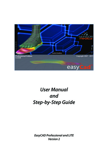
User ManualandStep-by-Step GuideEasyCAD Professional and LITEVersion 2Page 1
Table of ionInstalling EasyCADInstalling the programCompatibilitySystem requirementsBefore running the programApplication setupData centreSoftware settingsCAM SettingsGuide to Using EasyCADQuick Menu BarThe Main MenuThe ToolbarSub Menu Items under TOOLSGeneralInstrument AcquisitionObject LibrariesSelf-Modelling CAD and Creating Self-Modelling TemplatesOptimization ToolsSelection MenuFreehand ToolsRestore PointsDisply OptionF5 - Pressure OverlayF6 - ScannerF7 - 3D AcquisitionBorder Profile Graph (View parallel to the plane - F3)Transparency SliderArchive OptionsSingle Document ModeArchiveCreate a New PatientCreating a new Patient from the IMPORT optionCreating a New ProjectMethodologies for Building OrthoticsMethodology 1 - With SLS Scanner OnlyMethodology 2 - Using Biomechanical data and applying 3D imageMethodology 3 - Biomechanical data onlyMethodology 4 - Stuart Alexanders “quick” 212222222323232424273032Page 2
15.a.b.c.d.e.f.16.a.17.1.2.3.3.5.Step-by-Step GuideExporting from Medicapteurs Biomechanical PlatesUsing the SLS 3D ScannerProducing ISO FilesProducing ADM FilesTo Operate the Milling MachineSPECIAL FEATURESModelsFAQHow to Clean below the Vacuum bedCan I use my RS-ScanHow do I position the elements on the templates accuratelyMy Orthotics are not being milled in the middle of the BedI would like to increase/decrease the distance between the orthotics whenthey are being milled6. How to make a deep heel cup when using the Self Modelling Easy CAD tools.Page343434353637404041414142424243APPENDIX1 EVA Swatch2 Sizing Chart3 Sample of Templates for size 40 shoePage 3
IntroductionCongratulations on your purchase of EasyCAD!EasyCAD is an innovative three-dimensional software that offers all the possibilities for designing CADCAM orthotics.EasyCAD is not simply a CAD modelling software, but a complete tool for storing and printing of numerically controlled milling projects.Furthermore, for the Professional version, there is also a CAM module for post-processing of the projects(see Production)EasyCAD (Lite and Professional versions) is a program so powerful and complex, but at the same timeextremely easy to use.This manual will guide you step by step through learning the basics of Easy CAD orthotic design.1.Installing EasyCADa.Installing the programTo launch the EasyCAD installer simply double-click Setup.exe in the root folder of the CD. To access thisfolder you can use Windows Explorer or My Computer. After starting the program, a window of information for the preparation of the installation will open.Click on the Next button, which will give important information about the program.Click the Next button again. This opens a dialogue box where you can specify the installation path. Again,press “Next” to store your path selection. If something is wrong, simply press “Back” to return to the desired installation program and make your correction.By pressing “Next” you will run the installation. Depending on the speed of the system, this may take afew minutes.At the end of the installation you must restart the computer. You can then launch the program directlyfrom EasyCAD.b.CompatibilityEasyCAD is compatible with most video cards that support OpenGL 3D technology.In some cases, however, it has found that some integrated video cards are not able to properly handlethe 3D graphical environment of the program.In most cases the problem can be solved by going into Advanced Settings for the video card, thenchange the Hardware Acceleration back to it’s default setting.Page 4
c.System RequirementsOperating system: Windows 7 Professional or laterProcessor: Intel i5RAM: 4Gb or higherHard drive: 5Gb of free spaceVideo card: 512MB RAM or higher with minimum resolution of 1024x768Printer: Inkjet or laser, monochrome or colourBaropodometric systems supported:Sensor Medica 4040, 6050, 8040 16040, 24040, 32040 and Run TimeMedicapteurs S-Plate, Win-Pod and Win-TrackRS-ScanTekscanOthers on enquiryd.Before running the programWhen you first run the program, both for the Lite and Professional version for the Professional version,you must enter the activation code license to use the product.To obtain a valid EasyCAD license, please contact Ripple Effect Consulting.After entering the activation code click on the OK button.We recommend that you write down the activation code and store it in a safe place, as the code will needto be reused on the same computer if ever you need to format the hard drive or reinstall the product. Onsubsequent executions of the program you will no longer need to enter the activation code.To see which updates are available for the software, note also the version number shown on the panel onthe left.2.Application SetupBefore you start using the software, it is essential to correctly set the parameters for the application. –Settings (menu item) - Setup application can access the Setup procedure.3.Data centreEnter your details in the spaces provided. The information will be used both in the print sheet project andwhen the project is sent to the remote milling production centre.4.Software SettingsIn the submenu of software settings you can select the language of the software, as well as the unit ofmeasurement (metric or imperial).Page 5
5.CAM settingsFor those who have purchased a CNC Milling machine with the USBCNC program, it will be necessary toconfigure the parameters in this submenu for proper production of orthotics.In particular, to obtain accurate and reliable work, you must correctly set the parameters for the toolshank diameter and the diameter of the tool tip. To obtain information about these parameters refer tothe manual of the CNC milling machine and its configuration.These settings are effective only in EasyCAD Professional and are specific to the IMG 43 and Vulcan VX1milling machine. Should you have the Vulcan Twin machine please ensure you have the right version ofEasy CAD Professional.6.Guide to using EasyCADa.Quick Menu BarThe menu bar below shows you the fastest way to access the basic commands of the program.From left to right, the respective symbols represent the following commands:New Project: Creating a new project in a single document mode (see following paragraphs).Archive: Archive access of patients and projects.Open: Open a previously saved project, or as a document received from a remote centre (see sectionremote centers).Save: Saving a project in development.Print Preview: Print Preview of the project under development.Print: Print the project in development.Copy: Copies the selected data to the clipboard.Cut: Cuts the selected data to the clipboard.Paste: pastes the data previously saved to the clipboard.Page 6
View Plan: the three-dimensional representation enables or disables the display of the zero plane ofreference.View Edge: the three-dimensional representation enables or disables the display of the edge of the foot.Left foot: Go to the left foot to allow for the design.Right foot: Go to the right foot to allow for the design.Produce: Relevant to the Professional version only, converts the file to a type that is compatible with theCNC Milling Machine.Exit: Closes the program EasyCADb.The Main MenuThe main menu is all the functions available in the software itself. The menu is structured and dividedinto themes for ease of use even for less experienced users.For example, the FILE menu and all its entries, collects all the functions of opening, saving, exporting andprinting projects, including access to the archive. The menu can be activated from the keyboard usingthe Alt key.Some menus, when invoked, may refer to options on the toolbar. In these cases the panel will turn onautomatically.For example, in the main menu under the menu item “Tools” - EasyCAD self-modelling, the panel on theright of the screen will display pallet options with its configuration parameters.c.The toolbarThe toolbar, located to the right of the screen contains all the commands related to the design of computerized orthotics.Every single item in the toolbox gathers information, options and tools for designing computer-footorthotics.7.Sub Menu Items under TOOLSa. General InformationGeneral information shows a collected summary of theproject including the style of model template; the measureselected; the gender (man or woman) when provided; thematerial you want the orthotic milled on; the finish (coating) of the product; a text list of actions performed for thedesign of both the left and right foot.In this section, during the design of the orthotic, you canchange the material and finish using the appropriate dropdown menu.If you want to use materials or finishes not listed, you canclick through the [.] to activate the archive of materialsand finishes and include new ones (only if supported bythe milling centre, or for your records to cover yourself ).NB - To minimize menu click and drag on the small rowof dots at the top of the menu list.Page 7
b.Instrument AcquisitionYou can import tests from baropodometric platforms or photoelectric (optical scanners) of the mostpopular manufacturers in the world.After selecting the Open folder, choose the Pressure/3D file you wish to import .Adding .STL 3D ImageStep 1 : Click Instrument Acquisition in the Tools palletStep 2 : Click “Open” icon at the bottom of the windowStep 3 : Click “Import” buttonStep 4 : Select 3D SurveyStep 5 : Change drop down to STL FileStep 6 : Click “Open” icon under file.Step 7 : Select the Left Foot IconStep 8 : Click the open file iconStep 9 : Navigate to the file and select the STL file you want to openStep 10 : Choose 90 Rotation anti clockwiseStep 11 : Choose Flip ‘Y’ AxisStep 12 : Click on “Modify 3D File” menu itemStep 13 : Click the right foot iconStep 14 : repeat steps 8 to 12 to import the right foot STLNB - you can use the Cut tool and Fill surface tool in the STL editor to clean up the image beforereturning to Easy CAD.Step 15 : When you have imported and checked both 3D scans click “Save” button to return to Easy CAD.Step 16 : Reposition the foot on the template, then remove tick for smoothing and APPLYStep : 17 : When you are happy with the position of both scans click APPLYPage 8
YOU CAN TOGGLE BETWEEN YOUR PLATE’S DATA AND 3D SCANNER BY CLICKING ON THE “bpe”AND 3D BUTTONS ON THE RIGHT OF THE TOOLS PALLETNOTE: if at any stage 3D appears blue, click “display”and select 3D colourYou want the 3D image to be positioned as above (ienot flush with the heel of the template line, but thearch flush with the template border). At the end of thealignment, click Apply to confirm the import or OK toconfirm and return to the main orthotic design.When applying this image, it is recommended thatyou deselect smoothing (not as shown in image),and only smooth the plantar surface at the end of theproject. Page 9
Adding Biomechanical Plate DataStep 1 : Click “open” under the Tools pallet and go to Instrumental Acquisition.Step 2 : Click “Import” tabStep 3 : Select Podometer and make sure the drop down is YOUR PLATE ie WinPod, Win Track or RS Scan,etcStep 4 : Click “Open” icon under fileStep 5 : Select the file you want to import - double click on it.Step 6 : Press conversion buttonPage 10
Step 7 : Reposition your Left and Right scans on the templates.Step 8 : Click apply to add the data to your tools pallet. If the baropodometric pressure platform in your possession isnot among those listed in the system, through the appropriateTechnical Data panel you can set custom parameters to performthe data import. For more information on the platform, the structure of the files containing the test pressure in your possession,please contact the manufacturer.For each project you can import a plantar pressure test and a 3Dtest at the same time.Page 11
c.Object librariesObject Libraries lists options for the integration of classical objects arranged mainly used for the production oforthotics.To apply an object to the current project select the object from the list. In the preview pane a photograph ofthe object will display, click on Apply to place the insoleon the scene (box 2D and 3D).Each object is available in 4 different sizes, Small, Medium, Large and Extra Large, select the one best suitedto the project under development.In the Positioning Tab, adjust the position, height fromfloor and amplification of the shape.As an alternative to the Positioning arrows, you can dragthe object with the mouse (on the 2D image) and drop.For proper positioning it is recommended to use theruler available reference from the main menu, under theheading View - Ruler of reference.At the end of the positioning click Merge to Surface tocomplete the process and then continue with the otherchanges.Page 12
d.Self-Modelling EasyCADThe revolutionary self-modelling EasyCAD,through personalization and the combination ofparameters available, combined with the mostappropriate templates, allow you to create a baseplantar ideal for the project you want to accomplish.Easy-Cad is unique in offering a self-modellingsystem with the ability to create a virtually infiniteresource base foot.In addition, by applying a sophisticated mathematical algorithm to imported tests (pressure oroptical) the model created is able to fit the geometry of the patient’s foot. If you have importedthe Pressure map, it will ask if you would like thesettings you put here to work in conjunction withthe shape of the foot as shown in the pressuremap. By doing this, you will be able to generate atemplate with the arch shaped accurately.Creating Self-Modelling TemplatesUnder the options TAB you can save several templates of your Self-Modelling setups.This makes keeping a record of your favourite setting simple and easy.To re-use a saved tepmlate simple open theoptions tab
Software settings 5 5. CAM Settings 6 6. Guide to Using EasyCAD 7 a. Quick Menu Bar 7 b. The Main Menu 8 c. The Toolbar 9 7. Sub Menu Items under TOOLS 9 a. General 9 b. Instrument Acquisition 10 c. Object Libraries 12 d. Self-Modelling CAD and Creating Self-Modelling Templates 13 e. Optimization Tools 14 f. Selection Menu 15 g. Freehand Tools 17 h. Restore Points 18 8. Disply Option 19 a. F5 .

