Transcription
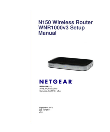
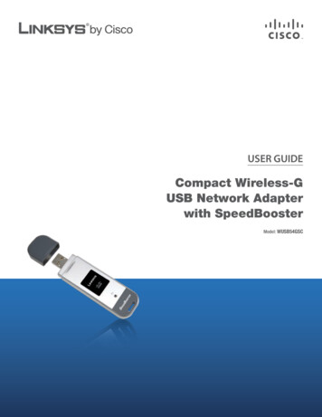
Wireless Field TestRF Scout Interference HunterFeatures & BenefitsSpectrum Analyzer– Preamp for Great Sensitivity– Seven Markers, Two Traces,Five Trace Modes for FlexibleMeasurements– Intermodulation MarkersAllow Quick Checks for thisCommon Problem– Specifications Optimized forInterference HuntingInterference Analysis Tool Set– Finds Interference Fast– Spectrogram Display forDiscovery and Logging ofIntermittent Signals– Signal Strength, AM/FMDemodulation and NoiseFloor Measurements Assistwith Identification andLocation of SignalsMulti-Standard Scannersfor Carrier IssuesExplore, Discover, Analyze and Document Interferenceand Coverage Issues In-Building and OutdoorsOutstanding InterferenceAnalysis CapabilitiesThe RF Scout is a rugged handheld toolthat helps with every aspect of RF signaldebugging and optimization. The RF Scoutdeals with out-of-channel interference, inchannel interference and coverage issues.And since a signal that might be good inone location can cause an interference orcoverage issue in another, the RF Scoutmaps those measurements.It provides all the tools needed forExploration, Discovery, Analysis andDocumentation of interference while theuser remains in the field. In addition, the– Reveals Many CommonCoverage Problems, bothIn-building and Outdoors– Scanners for GSM/GMSK/EDGE, UMTS/W-CDMA/HSDPA,cdmaOne/cdma2000 andcdma2000 1xEV-DO SignalsiMap Integrated Mapping Built-infor In-field Analysis of ProblemsFigure 1. In-building Signal Measurements,color coded for in-field analysis.RF Scout is designed to work both outsideand in-building. In this case, the whole istruly more than the sum of its parts.– Integrates any Spectrum,Interference or CarrierMeasurement Directly intoUser-provided Map– No Need to Return tothe Office for Analysisof Difficult Problems– Maps In-building Signalswith a Tap-and-Walkand-Tap Interface– Maps Outside, OptionallyDriven by GPSHandheld Form Factor––––Field TestedRuggedTouch Screen for Intuitive UseLong Battery LifeApplicationsExploration, Discovery, Analysisand Documentation of Interferenceand Coverage Issues both Indoorsand OutdoorsSignal Clearing During GreenField InstallsTroubleshooting Interference andCoverage Issues, both In-buildingand Outside
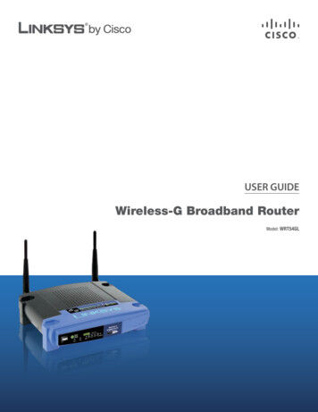
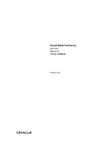
Wireless Field TestRF Scout Interference HunterFigure 2. Powerful handheld spectrumanalyzer with simple-to-use touch screeninterface.Handheld Spectrum AnalyzerThe RF Scout is a spectrum analyzerwith just the right set of capabilities forinterference hunting. The basic spectrumanalyzer has great sensitivity, a preamp,manual and coupled controls, two traces,seven markers, channel tables and all theother capabilities you would expect froma powerful handheld spectrum analyzer.But what makes this instrument excel isthe touch screen interface, which allowsshallow menu systems and an intuitiveuser interface, so it’s easy to find all of thecontrols. For instance, markers can beplaced by touching the screen above thedesired signal. Quick instrument manipulation translates to finding RF problemsfaster, particularly intermittent problems.2Figure 3. Spectrum/Spectrogram measurement easily spots intermittent signals.Interference Measurements:Intermittent SignalsWhile the RF Scout sensitivity allows usersto see interfering signals, the Spectrumand Spectrogram screen is great for bothidentifying intermittent signals and datalogging. The spectrogram allows users tocapture spectrum activity while displayingfrequency, time and power information.The spectrogram is capable of capturingdata over extended time frames of hours,days or weeks, and with time marks.This allows users to pin down just whenintermittent interference occurs withoutany need to personally be on-site.Spectrum and Spectrogram results canbe used for data logging, as mentionedabove. It is also possible to remotely controlthe RF Scout, using the Y400 Virtual CEoption. This allows users to monitor theprogress of the data logging, and see faultswhenever they occur, without traveling tothe signal monitoring site.Wireless Field Test www.tektronix.com/networktestFigure 4. Trace mask allows logging onlyviolations, reducing later analysis tasksSingle Point Data LoggingSometimes, interference locations areknown but the behavior or timing of thesignal is unknown. In this case, the RFScout can be used as a signal logger.With the addition of a compact flash ramand a PCMCIA adapter, the RF Scouthas quite a bit of data memory available.This memory can be used to recordspectrum traces, spectrum mask violations, spectrograms or scanner data.If an unusual signal is present, the RFScout can capture it.The automatically generated spectrummask (red), in combination with normaltraces (blue) and a min/max trace (mustard), is particularly useful since this allowsusers to ignore carriers and signals thatare known to be good and only save timestamped data when unusual signals arepresent. Early data reduction is importantwhen looking for intermittent problems.
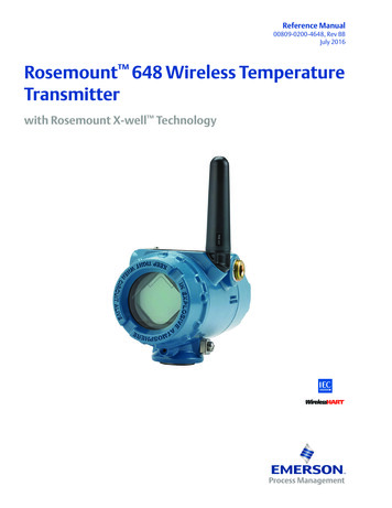
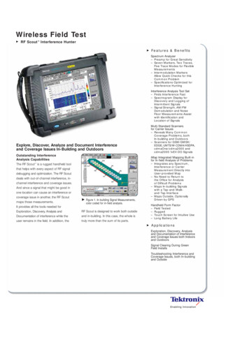
Wireless Field TestRF Scout Interference HunterFigure 6. GSM/TTDGT Channel Scanner.Figure 5. The RF Scout comes with many other interference tools.Figure 7. W-CDMA Scrambling Code Analysis.Interference Measurements:Locating and MeasuringThe RF Scout rounds out its interferencepackage with a quartet of popular interference hunting screens that techniciansand engineers have used for years to findinterference. The signal strength screenis the centerpiece of this set of measurements. This screen provides an easy wayto locate signals with an audible tone.This allows quick direction finding whileallowing your eyes to follow the aimingpoint of the directional antenna. Changingthe signal selected is as easy as touchingthe screen over the new signal to bemeasured. Field Strength is useful whenmeasuring human exposure to RF poweror when checking power at a location.A unique variation of the field strengthmeasurement allows measurements ofthe field strength of individual UMTS NodeB Scrambling Codes. AM and FM demodulation capability is useful when identifyingsignals by their sound or station ID. TheNoise Floor measurement gives users onenumber that reflects the overall receptionconditions for a given channel. Finally, codedomain and codogram measurements areprovided for cdma2000, W-CDMA and EVDO. Taken together with the spectrogramand spectrum analyzer capability, the RFScout offers a complete set of interferencehunting tools in a handheld form factor.Optional Scanner Set One:GSM/GPRS/EDGE andUMTS/W-CDMA/HSDPAThe GSM/GPRS/EDGE and the UMTS/W-CDMA/HSDPA scanner set add thecapability to evaluate coverage and cochannel interference from neighboring basestations. This enables RF Scout users todetermine the effect of many different NodeB or GSM base station adjustments. Thisincludes the effect of the adjustments on pilotpollution, in the case of UMTS and frequency reuse issues for GSM base stations.The GSM scanner identifies the channel,frequency, power, channel type, C/I and, ifthe signal is a control channel, the BSIC.The UMTS Scanner identifies the scramblingcodes, Ec ad Ec/Io for up to 10 codes.Wireless Field Test www.tektronix.com/networktest3
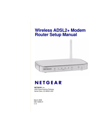
Wireless Field TestRF Scout Interference HunterFigure 9. In-building mapping is done witha Tap-and-Walk-and-Tap interface.Figure 8. cdma2000 and 1xEVDOPN Scanner.Optional Scanner Set Two:cdmaOne/cdma2000 and1x-EV-DO ScannersThe cdma2000 and the EV-DO scannerset add the capability to evaluate coverage and co-channel interference fromneighboring base stations. This optionautomatically identifies the 10 strongestPN Offsets for the 10 strongest pilotsand graphically displays their power level,timing error and Ec/Io. This enables RFScout users to determine the effect ofmany different base station adjustments,including the effects of adjustments onpilot pollution.4iMap Integrated Mapping OptionRF measurements, when made over theair, are location sensitive. A measuredvalue that might be good in one locationis interference in another. In addition, mostRF surveys create enough numbers thatusers resort to writing them down anyway,perhaps on a map. For this reason, theRF Scout can map its measurements,both for interference and coverage, usingon-board mapping capability for bothindoor and outdoor mapping needs.In-Building IntegratedSignal MappingIn-building mapping capability is illustratedabove, at an airport terminal. Measurements can either be placed directly onthe floor plan bitmap by the user, or beplaced automatically. A simple Tap-andWalk-and-Tap user interface automaticallypositions timed measurements alongcorridors and hallways. To make the displayeven more intuitive, the color of the measurement border represents signal strength.If more information is needed on a specificmeasurement, just tap the measurementbox. The RF Scout will show the full-screenversion of the measurement, allowingcomplete analysis of interference, coverageand distributed antenna faults in the field.Wireless Field Test www.tektronix.com/networktestFigure 10. Manual signal plotting providespower, location and direction for eachmeasurement.Outdoors Manual Signal MappingIn a similar manner, spectrum traces,interference measurements and carrierscans can be taken outdoors. Individualmeasurements can be placed on a bitmap, or any vector map converted from anumber of popular formats. Measurementicons can be placed on the map anddirectional arrows added to help in theanalysis. This allows users to have allsignal, location and directional informationon one screen, in one place so thatcomplex interference issues can besolved in the field.
Wireless Field TestRF Scout Interference HunterFigure 11. Automatic signal plotting showsgeographic signal changes.Automatic Outdoor GPSReferenced Signal MappingResults mapping can also be driven bythe available GPS. In this case, maps inseveral grid formats can be imported tothe RF Scout . Spectrum, interference orcarrier scans can be automatically placedon the map, by GPS coordinates, allowinganalysis in the field. Automatic measurements can be placed on the map every somany seconds, feet or meters. In addition,individual measurements can be placedon a map together with the automaticmeasurements, allowing users the abilityto get all the information in one spot.Geo-referenced results can be savedeither as a data table, or with a map.Data table results can be imported intoexisting popular mapping programs suchas MapInfo, for analysis along with othergeo-referenced data. Mapped results canalso be analyzed on RF Scout PC, thePC version of the RF Scout software,which runs on Windows laptops. So theRF Scout can be used to gather spectrumtraces, interference measurements andscanner results and then either analyzethe information in the field or integrate theresults with information from other measurement tools. The RF Scout provides thecomplete solution for interference analysis.Easy to UseThe RF Scout is based around the familiarWindows CE operating system. As a result,users will spend less time learning theinstrument and more time finding interference. The RF Scout puts measurementfunctions just a point of the finger away.Also, built-in help guides speed the measurement process, and common measurements have been optimized for quick,repeatable results. Finally, the WindowsCE operating system makes getting filesand data on and off the instrument easy.Figure 12. NetTek /RF Scout platformcombined with test modules.The Module and the PlatformThe RF Scout is a product conceived for RFperformance and optimization engineers.It consists of a Y400 base unit, a YBT250RF Module, one of several software packages, and optionally, a GPS unit, theYBGPS1. The Y400 platform includes thedisplay, power supply, CPU and battery.If you already have a Y400 and a YBT250,the RF Scout software can be installed onyour existing units. Available antenna testand T1/E1 modules allow you to tailor theRF Scout to service the standards andinterfaces in use in your network.The modular design also means that theinstrument can easily be upgraded. Newmeasurements or standards can beadded with software upgrades or withadditional modules.Wireless Field Test www.tektronix.com/networktest5
Wireless Field TestRF Scout Interference HunterCharacteristicsRF Scout YBT250 ModuleOperation ModesInputsRF – 50 Ω, type N female.External Frequency Reference – 50 Ω, type BNC (f).freqin –2, 4.8, 10, 13, 15 or 19.6608 MHz and others.Automatically detected.Timing Input – 10 kΩ, type BNC (f).1xEV-DO PN Offset ScannerInput Signal Range – –120 dBm to 30 dBm.Resolution –Io, Ec/Io, Ec: 0.1 dB.PN Offset: 1 PN Index.Outdoors Manual Signal Mapping.Standard Displays –Spectrum, Spectrum/Spectrogram, Signal Strength,AM/FM Demod, Noise Floor.Accuracy –Ec: 2.5 dB for Ec –95 dBm and Ec/Io –8 dB(typical).Tau – 0.5 chip of highest power multipath componentof each detected PN Offset, relative to input timingreference (ESC or YBGPS1).Automatic Outdoors GPS ReferencedSignal Mapping.Scanners, for Coverage andCo-channel InterferenceiMap MappingMap types Accepted –Spectral Analysis.Interference Analysis.Carrier Scanning.In-Building Integrated Signal Mapping.General SpecificationsFrequency CharacteristicsInput Range – 30 MHz to 2500 MHz.Internal Frequency Accuracy (Time Base Error) – 0.5 ppm ( 0.015 ppm typical, after GPS lock.Requires YBGPS1.)Internal Frequency Aging (Time Base Error) – 1 ppm/yr.Available Spans (in Spectrum Monitoring) –10 kHz to 2470 MHz.Resolution Bandwidths – 10 Hz to 6 MHz.Phase Noise – –75 dBc/Hz at 20 kHz offset.Amplitude Characteristics(CW or peak envelope, measured in 10 kHz span, typical)RF Field Strength – 0.75 dB: –20 dBm to 30 dBm, 0.5 dB, typical. 1.25 dB: –80 dBm to –20 dBm, 1.0 dB, typical.Amplitude Range – DANL 1 dB to 30 dBm.RF Input Overload Protection – 30 dBm to 50 W.Signal Related Spurious Response –IM3 better than –70 dBc, typical.2nd harmonic better than –60 dBc, typical.DANL ––152 dBm typical, 10 Hz RBW, 200 to 2000 MHz.Noise Figure – 10 dB, 200 MHz to 2000 MHz.Amplitude Display –10 Divisions; 1 to 10 dB per division.Spectrum Display Modes –Max, Min, Min-Max, Normal, Average, Dual Trace,Saved, Off.6Interference AnalysisGSM/GPRS/EDGE Channel ScannerInput Signal Range – –120 dBm to 30 dBm.C/I Ratio Range – 0 dB to 50 dB.Resolution –Frequency: 0.001 MHz.Peak Power: 0.1 dBm.C/I: 0.1 dB.Accuracy – 1 dB, –20 dBm to 30 dBm. 0.75 dB typical for identified GSM channels.W-CDMA/UMTS/HSDPA Scrambling Code AnalyzerInput Signal Range – –117 dBm to 30 dBm.Resolution – 0.1 dB.Accuracy (Ec) – 2 dB for Ec –102 dBm and Ec/Io –12 dB (typical).cdma2000 PN ScannerInput Signal Range – –120 dBm to 30 dBm.Resolution –Io, Ec/Io, Ec: –0.1 dB.PN Offset: 1 PN index.Tau: 0.1 chip.Accuracy –Ec: 2 dB for Ec –95 dBm and Ec/Io –8 dB(typical).Tau – 0.5 chip, of highest power multipath componentof each detected PNOS, relative to input timingreference (ESC or YBGPS1).Wireless Field Test www.tektronix.com/networktestUSGS DLG (*.opt) (PC-based converter provided).MapInfo (*.mif).ESRI ArcInfo Shape (*.shp) (PC-based converterprovided).Bitmaps (*.bmp).RF Scout map with results (.zip).Physical CharacteristicsYBT250 Test Module Weight – 1.4 kg/3.1 lbs.NetTek Mainframe Weight – 4.1 kg/9.04 lbs.Temperature –Operating –Specified temperature range: 0 ºC to 50 ºC.Functional temperature range: –10 ºC to 50 ºC.Storage – –40 ºC to 60 ºC.Calibration – 2-year cycle.Warranty – 1 kg1.4in.7.3759.51.25lbs.3.1
Wireless Field TestRF Scout Interference HunterOrdering InformationRF Scout YBT250 OptionsRF Scout software package run on a Y400 base unit and an YBT250 spectrum analyzer unit. Most options also require or recommend the YBGPS1 GPS receiver.RFS1RFS11RFS12RFS21RFS22Spectrum Analyzer andInterference AnalysisXXXXXiMap Integrated MappingXXGSM/GPRS/EDGE 00ScannerXXcdma2000 1x EV-DOScannerXXYBGPS1 RequiredXXYBGPS1 RecommendedXOpt. RFS1 – iMap, Spectrum Analysis andInterference Analysis.Opt. RFS11 – Spectrum Analysis, InterferenceAnalysis, GSM/GPRS/EDGE Scanner and UMTS/W-CDMA/HSDPA Scanner.Opt. RFS12 – iMap and Spectrum Analysis,Interference Analysis, GSM/GPRS/EDGE Scannerand UMTS/W-CDMA/HSDPA Scanner.Opt. RFS21 – Spectrum Analysis, InterferenceAnalysis, cdmaOne/cdma2000 Scanner andcdma2000 1x EV-DO Scanner.Opt. RFS22 – iMap and Spectrum Analysis,Interference Analysis, cdmaOne/cdma2000Scanner and cdma2000 1x EV-DO Scanner.Opt. L0 – English manual for YBT250.XServiceOpt. C3 – Calibration Service 3 years.Opt. C5 – Calibration Service 5 years.Opt. D1 – Calibration Data Report.Opt. D3 – Calibration Data Report 3 years(with Opt. C3).Opt. D5 – Calibration Data Report 5 years(with Opt. C5).Opt. R3 – Repair Service 3 years.Opt. R5 – Repair Service 5 years.Suggested RF ScoutY400 AccessoriesY400 Opt. VCE – Virtual CE Remote Control.One Additional Li-Ion Battery, for a Totalof Two, and 8 Hours of Use (Typical) –Order 146-0127-01.Mini Keyboard – Order 118-9402-00.YBGPS1 – GPS and Timing Referencefor the RF Scout.Suggested RF ScoutAccessoriesSniffer Antenna, Broadband – Order 119-6609-00.Beam Antenna, 824 to 896 MHz –Order 119-6594-00.Beam Antenna, 896 to 960 MHz –Order 119-6595-00.Beam Antenna, 1710 to 1880 MHz –Order 119-6596-00.Beam Antenna, 1850 to 1990 MHz –Order 119-6597-00.Magnetic Mount Antenna, 824 to 2170 MHz –Requires 103-0449-00 adapter. Order 119-6970-00.Antenna Adapter Type-N (M) to FME (M), for119-6970-00 Antenna – Order 103-0449-00.Wireless Field Test www.tektronix.com/networktest7
Wireless Field TestContact Tektronix:ASEAN / Australasia (65) 6356 3900RF Scout Interference Hunter Austria 41 52 675 3777Balkan, Israel, South Africa and other ISE Countries 41 52 675 3777Belgium 07 81 60166Pre-filter, General-purpose, 824 to 2500 MHz,Type-N (F) Connector – Order 119-7246-00.Pre-filter, 850 MHz Uplink Band, 824to 849 MHz, Type-N (F) Connector –Order 119-7245-00.Pre-filter, 850 MHz Downlink Band, 869to 894 MHz, Type-N (F) Connector –Order 119-7023-00.Pre-filter, 900 MHz Downlink Band, 921to 960 MHz, Type-N (F) Connector –Order 119-7022-00.Pre-filter, 1800 MHz Downlink Band, 1805to 1880 MHz, Type-N (F) Connector –Order 119-7021-00.Pre-filter, 1900 MHz Downlink Band, 1925to 1995 MHz, Type-N (F) Connector –Order 119-6972-00.Pre-filter, 2100 MHz Downlink Band, 2105to 2175 MHz, Type-N (F) Connector –Order 119-6971-00.Cable, 50 Ω, BNC (M) 3-foot (91 cm) –Order 012-0482-00.Cable, 50 Ω, Straight Type-N (M) and AngledType-N (M) Connector, 1.6 Foot (50 cm) –Order 174-4977-00.Cable, 50 Ω, Type-N (M) to Type-N (M)Connector, 3 Foot (91 cm) – Order 174-5002-00.Cable, 50 Ω, Low-precision Type-N (M) toType-N (M) Connector, 6-Foot Cable (1.83 m) –Order 012-0114-00.Cable, 50 Ω, Type-N (M) to Type-N (M)Connector, Low VSWR, High Shielding, 6 foot(182 cm) – Order 012-1683-01.Cable, 50 Ω, Precision, Amplitude and PhaseStable, Type-N (M) to Type-N (M) Connector,10 foot (3.0 m) – Order 012-1619-00.DC Block, Type-N (F) to Type-N (M)Connector – Order 119-6598-00.Calibrated Coupler, Type-N Connectors,500 to 1000 MHz – Order 119-6600-00.Directional Coupler, Type-N Connectors,920 to 2200 MHz – Order 119-6601-00.Power Splitter/Combiner, Type-N (F)Connectors, 1 W, 200 MHz to 2.5 GHz –Order 119-7024-00.Attenuator, Type-N (F) to Type-N (M)Connector, 50 W, 20 dB –Order 119-6599-00.Brazil & South America 55 (11) 3741-8360Canada 1 (800) 661-5625Central East Europe, Ukraine and the Baltics 41 52 675 3777Central Europe & Greece 41 52 675 3777Denmark 45 80 88 1401Finland 41 52 675 3777France & North Africa 33 (0) 1 69 86 81 81Germany 49 (221) 94 77 400Hong Kong (852) 2585-6688India (91) 80-22275577Italy 39 (02) 25086 1Japan 81 (3) 6714-3010Adapter, Universal Kit, 30 Pieces –Order 119-6602-00.Adapter, Type-N (M) to BNC (F) –Order 103-0045-00.Adapter, Type-N (M) to Type-N (M) –Order 103-0430-00.Adapter, Right Angle, Type-N (M)to Type-N (F) – Order 103-0448-00.Adapter, Barrel, Type-N (F) –Order 103-0429-00.Adapter, 7/16 (F) to Type-N (F) –Order 103-0431-00.Adapter, 7/16 (M) to Type-N (F) –Order 103-0432-00.Adapter, SMB (F) to BNC (M) –Order 174-3578-00.Luxembourg 44 (0) 1344 392400Mexico, Central America & Caribbean 52 (55) 56666-333Middle East, Asia and North Africa 41 52 675 3777The Netherlands 090 02 021797Norway 800 16098People’s Republic of China 86 (10) 6235 1230Poland 41 52 675 3777Portugal 80 08 12370Republic of Korea 82 (2) 528-5299Russia & CIS 7 (495) 7484900South Africa 27 11 254 8360Spain ( 34) 901 988 054Sweden 020 08 80371Switzerland 41 52 675 3777Taiwan 886 (2) 2722-9622United Kingdom & Eire 44 (0) 1344 392400Metal Cap, BNC – Order 200-0678-00.Metal Cap, Type-N – Order 200-4696-00.USA 1 (800) 426-2200For other areas contact Tektronix, Inc. at: 1 (503) 627-7111Updated 28 February 2006Our most up-to-date product information is available at:www.tektronix.comProduct(s) are manufactured in ISO registered facilities.Product(s) complies with IEEE Standard 488.1-1987, RS-232-C, and withTektronix Standard Codes and Formats.Copyright 2006, Tektronix. All rights reserved. Tektronix products are coveredby U.S. and foreign patents, issued and pending. Information in this publicationsupersedes that in all previously published material. Specification and pricechange privileges reserved. TEKTRONIX and TEK are registered trademarksof Tektronix, Inc. All other trade names referenced are the service marks,trademarks or registered trademarks of their respective companies.4/06HB/WOW2EW-19554-1
signal is unknown. In this case, the RF Scout can be used as a signal logger. With the addition of a compact flash ram and a PCMCIA adapter, the RF Scout has quite a bit of data memory available. This memory can be used to record spectrum traces, spectrum mask viola-tions, spectrograms or scanner data. If an unusual signal is present, the RF