Transcription
Cyclone:A Laser Scanner For Mobile Robot NavigationSanjiv Singh and Jay WestCMU-RI-TR-91-18The Robotics InstituteCarnegie MelIon UniversityPittsburgh, Pennsylvania 15213September 1991Copyright Q 1991 Carnegie Mellon University
Table of 14.25.IntroductionBackground & SpecificationScanner DesignConfigurationThe RangefinderInterfacing with the RangefinderScanner EnclosurePower and Communication EnclosureMotion ControlElectronic DesignThe Interface CircuitThe Data Buffer CicruitApplicationsObstacle DetectionUse on the LE (360 radial scan)Discussion1255688101112121215151618
List of Figures12345678910111213CycloneConfiguration of the systemThe rangefinderOperation of rangefinding deviceScanner enclosureTower motion sensorsPower and Communication EnclosureCommunication between the Interface Circuit and Data Buffer CircuitCommunication with the host computerCyclone mounted on the front bumper of NavLabThe "pendulum" mount for 3-D scanningCyclone mounted on the Locomotion EmulatorSample data obtained from the Cyclone167791011131415161617
AbstractResearchers at Carnegie Mellon’s Field Robotics Center have designed andimplemented a scanning laser rangefinder. The device uses a commerciallyavailable time-of-flight ranging instrument that is capable of making up to7200 measurements per second. The laser beam is reflected by a rotatingmirror, producing up to a 360 degree view. Mounted on a robot vehicle, thescanner can be used to detect obstacles in the vehicle’s path or to locate therobot on a map. This report discusses the motivation, design, and someapplications of the scanner.
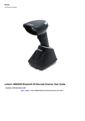
1. IntroductionRange information is essential for robot vehicle navigation. Even if a robot‘s path has beenpreplanned, in a realistic scenario, the robot must perceive obstructions that might interfere with its travel. We have designed and implemented a scanning rangefinder, Cyclone,that enables a robot vehicle to determine the three dimensional shape of its environmentwith high accuracy. The device, built over a period of 18months starting in mid-1987, hassince been used in various configurations for obstacle detection, collision avoidance andmore recently for position estimation. Obstacle detection is concerned with locatingobstacles in a vehicle’s future path so that the vehicle can decelerate from a high speed toa stop before it collides with the obstacle[ll. Collision avoidance involves navigating thevehicle around the detected obstacles to converge with the prespecified path[2]. Althoughthe device was originally designed for the afore mentioned applications, more recently ithas been successfully used for position estimation, which is the determination of vehiclelocation on a map using onboard sensors[3].At the heart of Cyclone is a time-of-flight ranging device that can make range measurements at up to 7200 hz.In conjunction with a rotating mirror arranged in a periscope likeconfiguration, the system is able to produce radial range scans. The scanner is shown inFigure 1.Figure 1: CycloneIn this report we discuss themotivation for such a device, its design and some of its applications. In section 2, we discuss relevant background work and resulting specificationsfor the scanner. In section 3 we discuss the design of the scanner. Section 4 brieflydiscusses the applications for which the Cyclone has been used so far. Section 5 discussessome of the salient development issues.1
2. Background & SpecificationHaving chosen ranging as the means to accomplish obstacle detection and collisionavoidance, it remained to choose from the many methods possible to obtain range information. In this section we discuss some of these methods and outline the resulting specifications for the scanner.Several surveys of ranging methods exist in the literature 1421 and we will onlybriefly review some of the common methods of obtaining range. Range sensing methodscan be classified as either passive or active. Passive methods derive range information byusing ambient energy, typically by analyzing video images of a scene. A commonly usedmethod is called ”computational stereo”. Either images from multiple cameras at fixedlocations (binocular/trinodar stereo) or image sequences from a moving camera(motion stereo) are used. Given a precise difference between camera locations and ameans of establishing correspondence between features in the various images, it ispossible to obtain range estimates from simple geometric relationships[6,71. Since computational stereo methods rely on finding a correspondence between features in separateimages, the computational effort for such methods depends on the scenes being imaged;in the worst case, a single range image may take minutes to compute. It may not bepossible to obtain any range information if the scene has sparse features and hence impossible to obtain a unique correspondence between features in the various images. Otherpassive methods have been proposed, for example depth from focusing[8] and from analysis of shading191 of a video image. In general passive methods are vulnerable to poorillumination conditions and have worked best in structured laboratory type settings.In contrast, active methods project energy onto the scene and are not constrained byambient lighting conditions. Active methods are further of several types. The simplesttype uses triangulation of a projected light beam, much the way that computational stereodoes. The correspondence problem is avoided because the projection of the beam can beeasily found in the image. The distortion produced by the effect of uneven terrain onstructured light can be used to produce three dimensional maps. The feasibility of severaldevices [lo, 11,121 using such a principle has been demonstrated over a range of 1-2 m.A second method transmits laser energy into the scene and measures the phase shift ofthe returning signal as compared to that of the outgoing signal. The phase shift can berelated to distance within the ambiguity interval of one wavelength. That is, such a sensorcannot distinguish between distance E and 1 E, where I is the interval of ambiguity corresponding to the distance at which the returned signal is exactly in phase with theoutgoing wave. Several devices have been built using this method, and to date thisremains the most commonly used method of laser ranging 1131.A third method measures time of flight that pulses of energy take to travel from the sensorto the scene and back.Time-of-flight devices that use ultrasonic, millimeter radar, andlaser wavelength waves have been built. Ultrasonic ranging devices can provide reasonable range estimates at small distances (approximately 10- 30 an)and coarse estimates atdistances of 2-5 m. The problem with sonar ranging is that most natural objects appear2
specular to ultrasonic energy and it is possible to get inter-reflections from corners veryeasily. That is, most surfaces reflect ultrasonic waves such that the angle of reflection(with respect to the surface normal) is equal to the angle of incidence. Very little energyis returned in the direction of the incident beam and quite often the returned signalmeasured is reflected off a second or a third surface before it arrives at the sensor. Further,ultrasonic waves are hard to calibrate, since the speed of sound changes with factors suchas humidity and temperature, and finally, ultrasonic waves have neither the range nor thespeed required for obstacle detection on a fast vehicle.For shorter wavelengths (as in mm radar and laser), the microstructure of most materialsallows the reflection of some energy back in the direction of the incident beam and thusthese methods have been more successful. Accurate ranging has been demonstrated byextremely expensive millimeter wave radar devices built for military applications.Though several prototype time-of-flight laser ranging devices have been built [14,151,until recently, commercially available laser ranging devices have been limited tomeasuring phase shift. Time-of-flight devices are considerably harder to build because ofthe timing resolution required it is necessary to clock pulses on the order of nanoseconds.Recently, some devices have become commercially available that allow the measurementof the time of flight of laser pulses. These devices, designed for surveying applications,have been demonstrated to measure distances up to 5 k m using retro-reflectors. Fornatural scenes, the range is much shorter, between 50 and 100m. There is a trade-offbetween the maximum range possible and the dynamic range (the difference between themaximum and the minimum range that can be measured). If it is necessary to makemeasurements over a large interval, the maximum range must be compromised.Our primary application, obstacle detection, dictated the functional specifications for thesensor, the scanning mechanism and the electronics:.Range measurements up to 40 m (maximum) and 3 m (minimum)*Maximum scan rate between 10-15 hz*Narrow vertical field of view (between 1-3 lines of range data)*Angular resolution of less than I degree*Robust enough to withstand extended use (4-6 hours at a time) in natural environments*Immune to high frequency vibrations from vehicle*Immune to electromagnetic noise in the environment*Able to relay data in real time*Flexible enough so that scanning speeds and angular resolution can be changed easily.*Cost not to exceed 30,000The most constraining requirement for ranging is the need to operate in outdoor environ-3
ments where the lighting cannot be controlled. This eliminates the choice of sensors thatuse passive methods since they are vulnerable to poor lighting conditions. The requirement for speed and accuracy eliminate the choice of sonar and the expense criteria eliminates the choice of radar. Laser ranging through the use of phase shift methods is areliable technology, but the sensors available at the time of design were limited to a rangeof approximately 20 m. Recently, some relatively inexpensive laser time-of-flight sensorshave been used for surveying applications. The dynamic range specifications and costlimitations led us to choose such an instrument. Further, it is a field tested device that hasendured a variety of operating conditions.The other main decision was that of scanner configuration, the mechanical system inwhich the laser is housed and which determines the distribution of the laser beamemanating from the range finder. Since the objective is to recognize obstacles on an otherwise flat road, we didn’t think it necessary to use a dual axis range scanner (with anodding as well as rotating mirror) that typically provides from 80 to 256 lines of rangedata per frame. Most of these devices are slow,providing 2 frames per second at the most.Rather, what we wanted was less data, but more often. It was estimated that 10 scanlines/second from a single line scanner would be necessary for obstacle detection atspeeds of 10 m/s.4
3. Scanner Design3.1. ConfigurationWe considered two configurations for the scanner to distribute a laser beam from a singlepoint source. The first one involved rotation of the entire rangefinding device. The advantage of such a configuration is that laser energy transmitted and received is not attenuatedby mirrors or prisms. However there are several complications. It is necessary to use alarge sophisticated slipring to transfer data and power to the instrument. Further, spinning a mass of several pounds brings risks stability, and increases vulnerability to naturalelements and accidents.The second configuration we considered used a rotating mirror to point the beam. Thisinvolved rotation of a tube containing a mirror (with an adjustable set angle) above therangefinder aperture. The advantage of such a method is that the rangefinder itself is notrequired to move, making a safer and simpler mechanism. This design was chosen andimplemented. Designed to be mounted on the front of an autonomous vehicle, the systemconsists of several parts:*Scanner enclosure: houses the rangefinding unit, a DC motor/encoder, rotating tower and an interface circuit*Power and communications enclosure (PCE):provides the power and control signalsfor the scanner motor. It also contains circuitry to buffer range data from the rangefinder and to relay these data to a host computer.*Host computer: connected to the PCE by a parallel data interface to read bufferedrange data. Apart from processing the range data, it is also responsible for sendinghigh level control commands (motor speed, etc.) to the PCE. These are then turnedinto low level controls sent to the motor.5
These modules are shown in Figure 2.Figure 2 Configuration of the system3.2. T h e RangefinderCyclone uses a customized version of a commercially available single point laser rangingdevice (RF-90) Salient features of the sensor are:'.Wavelength0.9 micrometerLaserGallium Arsenide SemiconductorPulse repetition rate7200 HzRange3-50mAccuracy /- 15 cmBeam spread2.5 mradResolutionPower requirements10 cm12 VDC,1A.The instrument is able to time the flight of laser pulses transmitted and returned fromnaturally diffuse objects. Figure 3 shows the configuration of the hand-held sensor as it iscommercially marketed. The device has been modified such that rather than being trig-1. Built by RadarTechnik and Elekmptik, Ausha.6
gered by hand, the laser is activated by a pulse train.Figure 3: The rangefkderFigure 4 shows a block diagram of the operation of the rangefinder.Targetconductorsrnitted PulseMeasunnDeviceeceived PulseReceiving LensFigure 4 Operation of rangefinding deviceOther researchers have done additional work on calibrating the sensor and have foundthat it is possible to reduce range error, especially for measurements taken from distancesof less 3 m [16,17].7
3.2.1. Interfacing with the RangeFinderWhen the rangefinder is triggered, the measured range is output on an 11 bit parallel port.Specifically,two control lines must be manipulated for the rangefinder to take a measurement:*TRIGGER is a control line that, when given a rising edge, causes the rangefinder toproduce a range measurement.*LASER-INHIBIT is a control line that must be driven low for the TRIGGER inputs tobe effective. We have used this line for safety purposes by ensuring that this line isnever pulled low unless the tower is rotating.Additionally, two status lines are available:-DATA-VALID is a status line. It is held high only when a good echo (reflected signal) is received by the rangefinder.*DATA-READY is a status line which is held high when the data are ready to be read.This line is always high except for 20 microseconds while the data are in transition.Reading data from rangefinder can be accomplished by the following algorithm. A countdown timer is started after a TRIGGER pulse is issued. Immediately, a loop is initiatedthat checks to see if the DATA-VALID line has been pulled high. If this doesn’t happenby the time the timer completes, the data are considered to be ”missing”. If the DATA-VALID line has been pulled high, then the algorithm waits for the DATA-READY line tobe pulled high. As soon as this is done, the parallel port can be read.3.3. Scanner EnclosureThe scanner enclosure houses the rangefinder as well as the necessary optics andelectronics. Figure 5 shows a cut away view of the scanner. The noteworthy componentsare as follows:*Rotating Tower: A rotating tower at the top of the scanner enclosure, contains a mirror that reflects the transmitted and receiving beams. The tower is driven by a cogbelt powered by a motor. There is a 21 gearing ratio between the motor and thetower. A four point bearing is used to hold the tower rigidly.*Motor/Encoder: A DC stepper motor is used to drive the rotating tower. The encoder allows for the motion control to determine position of the motor shaft to within0.2 degrees.-Interface Circuit: This circuit is responsible for relaying power and data between thescanner and the remote PCE.
500 Line Encodernterface CircuitFigure 5 Scanner enclosure*Tower Motion Sensors: These sensors, mounted directly below the tower, have twofunctions. Firstly, they ensure that if the speed of the tower falls below a minimumspeed, the laser is disabled from firing, so as to not repeatedly fire the laser at onespot. This is a safety feature designed to minimize exposure to eyes, in case thetower stalls for some reason. A second sensor is used to mark an angle (betweenthe two sensors) in which the laser can be selectively disabled. Typically, the laserscanner is mounted on the front of a vehicle, and the field of interest is in the 180degree area in front of the vehicle. The vehicle itself will block the rear portion ofthe 360 degree scan area. The second tower motion sensor enables the determination of whether the tower is pointing out in front of the vehicle or towards it. Thisinformation can be used to disable the rangefmder from firing when the tower ispointing towards the vehicle. The second motion sensor is mounted 170 degreesaway from the first one. This is used to indicate a "deadband on part of the 360deg e e view(Figure 6 ) .9
Tower Motion SensorsFigure 6 Tower motion sensors3.4. Power and Communication EnclosureAs mentioned previously, the power and control signals are not generated in the scannerenclosure. Instead a separate enclosure has been designed W E ) . When the cyclone ismounted on the front of an autonomous vehicle, the PCE is rack mounted in the interiorin a 19” rack. The PCE houses the following:*Data Buffer Circuit: generates the control signals for the rangefinder, and buffers therange data till a complete scan can be transmitted to the host computer.*Motor Amplifier: generates the power and control for the motor that drives the tower.*Power Supply: Converts the AC voltage to DC for use by the buffer circuit (12 V@0.25 A,5V @3A) and to power the rangefinder (12 V@ 1A) and the interface circuit (5V @ 0.1 A).The configuration of the PCE is shown in Figure 7.10
Data toComputerDataBufferData from RangefinderControl to-Laser4I-1Control to MotorAC-DCPowerIIMotor ControllerFigure 7 Power and Communication Enclosure3.5. Motion ControlIt is necessary to precisely control the speed of the scanner tower and hence the speed ofthe DC motor used to drive the tower. We were looking for a motion control system thatafforded us the following:*Precision of control: max 0.1% error in rotational velocity*Simplicity: a simple stand-alone system that can communicate over a serial interfacefor high level commands and diagnostics.ability to synchronize: each data set should be distinct, i.e, it is necessary for the motor to be repeatedly synchronized with the zero angle.We chose a high resolution DC stepped motor' that is controlled by a single stand-aloneunit providing all the necessary control and power to drive the motor. This device has25000 steps/rotation and is comparable in smoothness to the DC servo motor. This motorprovides 45 in/oz. of torque. Its top speed is 1800 RPM corresponding to 15 rotations/secof the tower. Specifications of commands like motor speed and motor diagnostics areachieved through a serial interface on the motor controller.An encoder is mounted on the shaft of the motor and provides three separate lines fromwhich the position of the motor shaft can be precisely determined. Channels "A" and "B"produce a pulse train of 500 pulse/rotation that is 90 degrees out of phase. This provides2000 edges (1000risingand 1000 falling)from which the angular position of the motor can1. Manufactured by Cornpumotor Inc.11
be determined. The ‘ Z channel produces a pulse whenever the motor completes onecomplete rotation.3.6. Electronic DesignThere are two main circuits: the Interface Circuit that resides in the scanner enclosure, andthe Datu Buffer Circuit, that resides in the PCE. The interface circuit transmits range dataas it is obtained to the data buffer circuit via differential drivers and receivers. Range dataare collected by the Data Buffer Circuit until the tower makes one full revolution. Thesedata comprise one scan. When a scan is complete, the buffer circuit signals the hostcomputer, whereupon the entire scan is transferred to the host computer for processing.3.6.1. Interface CircuitThe Interface Circuit has three functions. First, it acts as a safety monitor. It uses one ofthe tower motion sensors to sense if the tower has stopped rotating. In this case, theLASER-INHIBIT signal is pulled high and the rangefinder is disabled from firing. Thesecond function is to disable the laser from firing for part of the 360 degree scan area asmentioned earlier. This feature extends the life of the laser diode and also makes itpossible to rotate the tower at a faster rate because the 7200 Hz firing rate is a RMS specification. However, for applications where a 360 degree scan is needed, the disable featurecan be turned off.The third function of the circuit is to convert signals between single ended and differentialform. Tn signals (range measurements) from the rangefinder are differentially transmitted to the buffer arcuitry, and differentially transmitted signals from the buffercircuitry are converted to TIL levels. That is, each signal is transmitted on two separatelines, such each signal is now the difference between the voltage on two lines. Ambientnoise affects both lines equally, but difference between the two lines is preserved. Thisprocedure prevents noise contamination along the cable connecting the scanner and thePCE.3.6.2.Data Buffer CircuitThe Data Buffer Circuit has three functions: to synchronize firing of the laser with theangular position of the tower, to buffer range data from one complete scan, and totransmit the scan to a host computer. Scan data are collected and stored in two memorybanks. This avoids shared memory and synchronization problems between scan storageand scan transmission. Data for a new scan is stored in one bank while the previous scanis being transmitted from the other bank. This allows for more effective utilization of theCPU on the host computer since the host computer receives a whole scan at a time, ratherthan having to fetch one range measurement at a time.Synchronization of the scans, i.e. correct detection of the start of a new scan is accomplished by the use of two quadrature pulse trains issued by the encoder: the Z and Achannels. The 2 channel is asserted once per motor shaft revolution. The A channel pulses12
1000 times per revolution of the motor shaft. One additional signal is needed to fullysynchronize the scan field with the encoder signals. Since there is a 2:l gearing ratiobetween the motor and the tower, two pulses are received on the 2 channel and 2000pulses are received on the A channel per rotation of the tower. It is therefore not possibleto differentiate between the beginning of the first half of the scan and the beginning of thesecond half. To fully synchronize the scan field, the DB (dead band) signal generated bythe interface circuit is used. The DB signal, used to disable the laser from firing in the backhalf of the scan, allows the differentiation of the front and back halves of the scan. The Zand DB signals together indicate the beginning of the scan.The second task, buffering data for one complete scan, is accomplished through the Achannel. The 2000 pulses of the channel are divided by either 2, 4, 8, or 16 (selectedthrough DIP switches on the circuit board). This allows the number of data points perscan to be varied between 1000,500,250, and 125. The divided signal is used to trigger thelaser rangefinder at appropriate angular intervals, and to store the resulting range data inmemory.The sequence of events is as follows. W (write) is asserted one clock cycle after a risingedge on the divided A signal. At this point, data from a previous T (laser trigger) is available and is stored in memory. T is asserted the following clock cycle, triggering the laserand putting the resulting range data onto the memory input bus. This data are written onthe next W pulse, repeating the cycle. The timing relationships are depicted in Figure 8:CLKFigure 8: Communication between the Interface Circuit and Data Buffer CircuitThe final task of the buffer circuit is to transmit the scan data to a computer forprocessing. Completed scans are signaled by the Z and DB signals (the beginning of ascan is also the end of a previous one). Upon sensing a completed scan, an interruptrequest line is asserted and remains so asserted until either the mirror has made half arevolution or the computer acknowledges the interrupt. In the first case, the half revolution of the mirror is signaled by a subsequent 2 pulse and indicates a time out condition;the computer has failed to respond and the data are lost. Normally, the interrupt isacknowledged by the host computer and upon its receipt, STR (data strobe) is assertedand held until IBF (input buffer full) is received. During this time, data are put on thedata bus and may be read by the computer. Data is valid on the bus until IBF is asserted,13
at which time STR is deasserted and the data removed from the bus. Once the computerdetects the de-assertion of STR,it deasserts IBF. This causes STR to be asserted for thenext piece of data, repeating the cycle. The simplified timing diagram is shown in Figure9.1CLK14
4. Applications4.1. Obstacle DetectionIn our early obstacle detection an. avoidance experiments, we mountel Cyclone on i iefront bumper of the Navlab. In this configuration, the scans lie in a plane parallel to theground plane and only obstacles higher than this plane can be detected. This configuration is shown in Figure 10.Figure 1 0 Cyclone mounted on the front bumper of NavLabThe scanner is mounted on a "L" bracket using five shock mounts to damp out highfrequency vibration which are mainly induced by the vehicle engine.Cyclone was also used in a downward looking configuration to obtain three dimensionalinformation about the terrain. In Figure 11, the scanner is shown mounted in a"pendulum" configuration atop of the cab of the NavLab. The scanner pivots arqund ahorizontal axis to the ground plane and runs through the left and right sides of thescanner. The downward pointing angle can be adjusted by a link at the bottom of the15
scanner.I I-I-nFigure 11: The "pendulum" mount for 3-D scanning4.2. Use on the LE (360radial scan)More recently, Cyclone has been used for position estimation on the LocomotionEmulator (LE), one of the robots developed at the Field Robotics Center. Given theangular resolution and range accuracy of the scanner, it is possible to match features inthe range data to known features on a map such that the position of the robot can belocated to within 10 an.Figure 12 shows the Cyclone mounted on the LE.Figure 12: Cyclone mounted on the Locomotion Emulator16
Figure 13 shows data from a single scan taken from the Cyclone while the LE was navigating in an underground mine intersection. This scan consists of 1000 range measurements.I -Figure 13: Sample data obtained from the Cyclone17
5. DiscussionDevelopment of a stable system was complicated by several factors. Firstly, we wereplagued by electrical noise problems. The stepper motor used to drive the scanner towerwas the largest source of noise. Even after much shielding, data communication wasconstantly contaminated. This problem was solved by differential transmitting all signalsbetween the scanner enclosure and the PCE.We had a hard time finding a glass dust cover for the front of the tower. We found thatquite often laser pulses were reflected back from the glass cover and were accepted aslegal echoes. This was despite many efforts to treat the window with special coatingsmatched to the frequency of the laser, and to tilt the window. This problem has never beensolved and it was determined that a modification in the rangefinder itself is necessary tocompensate for this phenomena. For our experiments, we ended up manually removinga metal dust cover as necessary. Under most operating conditions (i.e. in the absence of alot of dust), motion of the tower is sufficient to keep dust from entering the scanner.A different set of problems are application dependant. For exampl-e,at high speeds, thelines traced by a scan on the ground (while mounted in the downward looking configuration) are not orthogonal to vehicle motion but lie at a velocity dependant angle to it.This is due to the relatively large amount of time taken by the rotation of the tower; thetower speed must be increased proportional to the higher vehicle speeds to prevent thiseffect. Another problem is due to the pitching motion of the vehicle that the Cyclone ismounted on. Given the small vertical field of view, the scan could completely miss theroad (and hence any obstacle) or give the erroneous impression that the road surface liesmuch closer thanexpected. It is necessary to actively servo the pitch axis of the scanner tomaintain a desired downward looking angle. This issue was also never dealt with.Cyclone has proven to be a much larger success for applications other than the onesit was designed. Recent results in map based position estimation when mounted on aslow moving vehicle, navigating in underground mines, are unprecedented. The-rangeand the accuracy affordedby the system make it ideally suited for this sort of application.
AcknowledgmentsThe authors would like to acknowledge Kevin Lynch and Thanathip Vidyasirinun fordeveloping early versions of the buffer circuitry. Gary Shaffer helped in the many nightsspent debugging the system and wrote helpful software utilities to view the data. LonnieDevier assembled and disassembled the scanner many times and helped with much of themounting work. Richard Clow performed many of the calibration tests. Bryon Smithdesigned and built the safety sensor and Gary Baun
The scanner is shown in Figure 1. Figure 1: Cyclone In this report we discuss themotivation for such a device, its design and some of its appli- cations. In section 2, we discuss relevant background work and resulting specifications for the scanner. In section 3 we discuss the design of the scanner.