Transcription
LouversEngineering GuideSelecting the Right LouverWhen selecting a louver, there are several factors that should be considered:a) Architectural considerationsb) Locationc) PerformanceFREE AREA The minimum area through which aircan pass within a louver is called thefree area of a louver1. The free area of a louver is criticalto its overall performance and mustbe considered during its selectionprocess. The free area has a direct effect onthe air velocity though the louver: lessfree area creates higher air velocitiesthus a higher pressure drop. For intakeconditions, higher air velocities equalhigher water penetration. Everything being relative, this is truefor all types and models of louvers. Whenever free area percentages areused always state the louver size onwhich it was calculated. (Publishedfree area data is based on 48” X 48”louver)Although it is evident that free areavaries with louver size, when a louveris selected for a low height application,the free area drops much faster thanexpected. This effect is most drastic asthe louver height approaches 3 to 4 timesthe louver depth. Since the head andsill of a louver are of a fixed height, thespace they occupy becomes important,thus reducing considerably the amountof available blade face area (and thusfree area). As an example, a 48” x 48”x 4” deep louver may have 8.8 sq.ft. offree area (55%), a 48” x 12” of the samemodel would have 1.5 sq.ft. (37%). Asa general rule, avoid selecting a louverwhen its height is less than 4 times itsdepth. The actual free area shouldalways be checked when designing alouver below 48” in height. When thelouver height exceeds 48”, the percentage of free area will increase slightly.1AMCA PUBLICATION 501-93, Application Manual for Air LouversENGINEERING GUIDE - LOUVERSa) Architectural considerations:Louvers can be built in multiple sections with visible mullions both vertically and/or horizontally or they canbe built in a continuous blade method(CB) offering an uninterrupted bladeline. They can also be built into a penthouse with mitered or box corners.b) Location:When louvers or penthouses areinstalled at ground level where theycan be subject to physical abuse,consideration should be given totheir structural strength. In thesecases, steel or heavy 8 ga. aluminiumconstruction should be considered.c) Performance:When discussing performance, fourmajor topics must be considered:First consideration: Copyright Price Industries 2016.All Metric dimensions ( ) are soft conversion.Imperial dimensions are converted to metric and rounded to the nearest millimetre.3
LouversEngineering GuideSelecting the Right LouverSecond consideration:Third consideration: Although water penetration data ispublished based on the AMCA Standard 500 test method, its primary useis for comparison purposes betweenmodels and suppliers and of limiteduse in the design process since winddriven rain is not included. No accurate method exists at this timeto design and select an intake louverbased on water penetration. Experience has shown that selectingan intake louver with a reasonablemargin of safety below the BeginningPoint of water penetration (as definedby the AMCA Standard 500L) will avoidsignificant water penetration undersevere storm conditions. Water penetration is not consideredon exhaust louvers; the selection isusually based on the permissible pressure drop. It must be recognized that all louvers(intake and exhaust) will permitsome degree of water penetrationwhen exposed to wind driven rain.Floor drains should be provided in theplenum behind the louver. A new test method that includes winddriven rain was being released byAMCA in 1999 (AMCA Standard 500L1999). At this time, no test data exists on snowpenetration through louvers. The sizing of a louver for a desired pressure drop and air flow rate is greatlysimplified with the unique PRICENOMOGRAPHS: refer to the appropriate sheet and “How to use PRICENOMOGRAPHS” for details (see pageAA-11).They also permit quick selectionbased on free area and airflow rateor louver dimensions and free areavelocity or any other combination ofparameters as a starting point. PRICENOMOGRAPHS have been preparedfor fixed blade and adjustable bladelouvers and penthouses. When installing a damper behind afixed louver, the total pressure dropcan be unpredictable. Use a louver withan integrated damper (combinationlouver) which is built as a single unit,the performance is tested and predictable. The pressure drop curves of louversare based on free area velocity andvary very little, depending almost exclusively on the shape of the air passagebetween the blades. Screens can add a pressure dropincrease of up to 10%. Fine mesh screens (insect screens)should always be made easily removable and installed only during criticalperiods.They must be cleaned regularlyto remove dirt and debris.WATER PENETRATIONPRESSURE DROPFourth consideration:WIND LOADS andSTRUCTURAL ELEMENTS As a standard, all PRICE louvers builtin a single section are designed to support a 25 psf (100 mph) wind load. All louvers having 2 sections in widthby 2 sections in height or more mayrequire additional structure to supportthe wind load. Louvers greater than 72” in width by 2sections in height or more may requireadditional structure to support thewind load. Splice angles used to join sections inheight are for alignment purposes onlyand cannot be considered structuralelements. Since louver blades are welded to thejambs, securing a louver section byits jambs and central blade support,(if used) is considered acceptablepractice.ENGINEERING GUIDE - LOUVERSGeneral Selection GuidelinesNote for louvers in multiple sections:Louvers built in multiple sections are designed with provisions for thermal expansion and when installed, should never bebutted together. When the temperature varies between -35 C to 40 C, the thermal expansion of a 10 ft [3m] aluminiumlouver is almost ¼” [6mm] (steel louvers expand half this amount).4All Metric dimensions ( ) are soft conversion.Imperial dimensions are converted to metric and rounded to the nearest millimetre. Copyright Price Industries 2016.
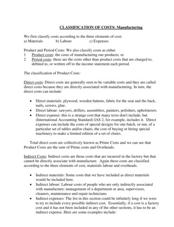
LouversEngineering GuideField Measurement InformationOnce the louvers have been approved bythe architect, the louvers can be releasedfor production. Before you can proceed, theopening dimensions must be confirmed.Thenext step is critical in ensuring that the louverinstallation will go smoothly: you must makefield measurements of the opening and record the job site conditions and any obstructions. Improper information at this point orneglecting to check all the job conditionscan have dire consequences later.Step 3. Square and Rectangular LouversW TOPHHLEFTFor this reason PRICE has developed a stepby step method to assist you in completingthis essential task.Basic principle: The basis of precise fieldmeasurements is the use of the principle oftriangulation. Once you know the lengths ofthe three sides of a triangle, that triangle isunique and fully defined. The angles at thecorners are no longer required. Thus anyshape can be sub-divided into a series oftriangles and be precisely defined with thedimensions of their sides.RIGHTW BOTTOMStep #3a: Measure the opening width and heighton all 4 sides.BAStep 1. Study the architectural drawingsand approved submittal drawings to fullyunderstand how the louvers are intendedto be installed on the project, how they areto fit in the openings and how they are tobe attached in those openings.Step 2. You can now proceed with theStep #3b: Measure the diagonal distances betweenopposite corners.opening measurements. Prepare a sketchof each louver viewed from the exterior andidentify its location.LEFT SIDEBOWBOTTOM BOW Copyright Price Industries 2016.All Metric dimensions ( ) are soft conversion.Imperial dimensions are converted to metric and rounded to the nearest millimetre.ENGINEERING GUIDE - LOUVERSStep #3c: Use a string to see if the sides of theopening bows in or out. If an inward bow isdetected, rectify it if possible. For thosethat cannot be rectified, record them onyour sketch.5
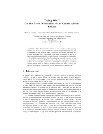
LouversEngineering GuideField Measurement InformationStep 4. Right Angle Triangular LouversExterior ElevationDDBOWHW BOW90 WStep #4a: Measure the opening width, height anddiagonal side. Based on these dimensions,louver dimensions will be corrected to obtain90 between width and height.Step #4b: Use a string to see if the sides of the openingbows in or out. If an inward bow is detected, rectify if possible. For those that cannot be rectified,record them on your sketch.Step 5. Common Triangular LouversExterior ElevationNote: Dim. A and C are notnecessarily equal.C BOWACBBOWBStep #5b: Use a string to see if the sides of the openingbows in or out. If an inward bow is detected, rectify if possible. For those that cannot be rectified,record them on your sketch.ENGINEERING GUIDE - LOUVERSStep #5a: Measure the 3 sides of the opening.6All Metric dimensions ( ) are soft conversion.Imperial dimensions are converted to metric and rounded to the nearest millimetre. Copyright Price Industries 2016.
LouversEngineering GuideField Measurement InformationStep 6. Circular, Semicircular and Ogive Shaped LouversExterior ElevationsABCFGABEHCDIFor openings of 72" [1829] or less.Step #6a: If the circular opening is relatively small andhas a consistent circumference, you can measure the diameter in 3 or 4 locations and recordthe smallest dimension. For larger or irregularopenings, mark the circular opening in 6approximately equidistant points on the edgeof the opening. Measure the distances A, B, Cand the actual distances D through I. By theuse of computer assisted drafting (CAD), a truecircle will be fitted to the actual opening.Note: Dimensions D through I should be approximatelyequal to the radius of the circle.Exterior ElevationsDDEABEBFGHCFGHWWStep #6b: Mark the circular portion of the opening in 4approximately equidistant points on its edgeopening. Measure the distances A, B, G, H, Wand the actual distances C through F. By the useof computer assisted drafting (CAD), a truecircular portion will be fitted to the actualopening. Copyright Price Industries 2016.Step #6c: Use a string to see if the base of the openingbows in or out. If an inward bow is detected,rectify it if possible. If it cannot be rectified,record it on your sketch.All Metric dimensions ( ) are soft conversion.Imperial dimensions are converted to metric and rounded to the nearest millimetre.7ENGINEERING GUIDE - LOUVERSAC
LouversEngineering GuideField Measurement InformationStep 7. Louvers Shapes with 2 Vertical Parallel SidesExterior ElevationsDDRDLAWTBHRAHLHLHRB90 90 WWBWDTBHRHRABHLAHLENGINEERING GUIDE - LOUVERSDBDStep #7a: Divide opening into rectangles and trianglesand treat as in Steps #3a through 5b. Based onthese dimensions, louver dimensions will becorrected to obtain parallel sides and/or 90 between width and height.8Step #7b: Use a string to see if the base of the openingbows in or out. If an inward bow is detected,rectify it if possible. If it cannot be rectified,record it on your sketch.All Metric dimensions ( ) are soft conversion.Imperial dimensions are converted to metric and rounded to the nearest millimetre. Copyright Price Industries 2016.
LouversEngineering GuideField Measurement InformationStep 8. Irregular Shaped LouversExterior ElevationsAABYCFXEGBYXDStep #8a: After measuring the 3 sides of the opening,draw a horizontal line to establish the bladeorientation and measure distance X and Y.CStep #8b:Measure the distances A through E.Divide shape into simple triangular shapesand measure the remaining distances F and G.Draw a horizontal line to establish the bladeorientation and measure distances X and Y.Step #8c:Use a string to see if the base of the openingbows in or out. If an inward bow is detected,rectify it if possible. If it cannot be rectified,record it on your sketch.Section ASection BX Copyright Price Industries 2016.All Metric dimensions ( ) are soft conversion.Imperial dimensions are converted to metric and rounded to the nearest millimetre.ENGINEERING GUIDE - LOUVERSLarge shapes divided into sectionsWhen a louver shape is divided into sections by visiblemullions or when various louver shapes are interdependentand if the blades must line up in the final assembly, alwaysinclude a sketch of the relative positions of the individual shapes.Section CY9
LouversEngineering GuideField Measurement InformationLouver UndersizingLouver FlangesStructural SupportAllowance must always be made in the finalsizing of the louver to compensate for theirregularities in the sides of the opening,thermal expansion and caulking. By alwaysgiving the actual opening dimensions witha clear indication of nonlinear conditionson the opening edges, proper undersizingcan be achieved. This is especially true forlouver shapes.As a standard practice, PRICE will manufacture the louvers with a minimum ¼” (6mm)gap all around. If a different gap is preferredbe sure to indicate it on your order.Thus, for a 48" by 48" opening without excessive bowing of the sides of the opening, theactual louver size, as manufactured, wouldbe 47.5" by 47.5".Although flanges of various widths areavailable, the most common flange is1½”(38mm). The flange width is defined asthe width that exceeds the louver frame.Thus, the overall size of a louver with 1½”flanges to fit a 48" x 48" opening wouldbe 50½” by 50½” and would exceed theopening by 1¼”.48" x 48" opening less undersizing (2 x¼”) 47½” x 47½” louver with flangesadded (2 x 1½”) 50½” x 50½” overallWhen the louver comes in several sections,structural supports must be provided tosecurely attach these sections to the building. In most cases, these structural elementsare installed ahead of time by others andtheir exact location “as installed” must beverified to ensure that their location matchesthe louver submittal drawings. If required,changes can be made to relocate the mullions on the louvers before they are put intoproduction with little or no cost.Here are other questions which may haveto be addressed:Is there adequate space behind thelouver to permit fastening frominside?Are there any structural or other elements that might interfere with thelouver?Are the vertical edges of the openingsufficiently rigid to attach the sides ofthe louver?Sill Extension or Loose SillsENGINEERING GUIDE - LOUVERSLoose sills or sill extensions are used todeflect rain water away from the sill of thelouver towards the exterior of the building.They are designed to maintain a continuouswatertight ledge under the louver extendingdownwards from its backside towards theexterior finished wall. To establish its propersize, measure the distance between theproposed location of the louver face to thefinished face of the building, add the overalllouver depth plus ¼” [6mm]. In some cases,sill extensions may be shipped in sections;always give the opening width so that sufficient overlap can be allowed for.Louvers in Multiple SectionsLouvers built in multiple sections aredesigned with provisions for thermalexpansion and when installed, should neverbe butted together. When the temperaturevaries between -35ºC and 40ºC, the thermalexpansion of a 10 ft [3m] aluminum louveris almost ¼” [6mm] (steel louvers expandhalf this amount).10StandardInstallationContinuous BladeInstallationAll Metric dimensions ( ) are soft conversion.Imperial dimensions are converted to metric and rounded to the nearest millimetre. Copyright Price Industries 2016.
Extruded AluminumLouvers Performance DataHow to Use the Price NomographsPRICE has developed this unique graphi-cal tool to help you select PRICE louverswithout the use of a calculator.All you need is a ruler and a pencil. Amultitude of “what if” conditions can bequickly evaluated and the working copyof the nomograph can be retained for future reference.Step 1.To use the PRICE Nomographs,you need to know at least 3 of the following 6 variables: the louver width andheight, the louver free area, the air volume, free area air velocity or static pressure loss. The possible starting pointcombinations are as follows:One louver dimension – flow rate – freearea velocityOne louver dimension – flow rate - pressure dropOne louver dimension – flow rate – freeareaTwo louver dimensions – flow rateTwo louver dimensions – pressure dropTwo louver dimensions – free area velocityStep 2. The PRICE Nomograph is comprised of 2 interrelated areas. The dimensional characteristics are on the left sideof the sheet and the air flow characteristics are on the right. Drawing a line joining the “Louver Width” (W scale) to the“Louver Height” (H scale), you obtain thefree area as the line crosses the “LouverFree Area” (A scale). You can also startwith the free area and one dimension toobtain the 2nd dimension.Step 3. Drawing a second line joiningLOUVERSthe “Louver Free Area” (A scale) (obtained in step 2) to the “Louver Air Flow”(F scale), you obtain the free area velocity and pressure drop as the line crossesthe “Pressure drop / Free area velocity”(P-V scale). The line can also be drawnwith any combination of 2 starting points:[free area & pressure drop] or [flow rate& pressure drop] or [flow rate & free areavelocity].The PRICE Nomographs give you maximum flexibility in the selection of yourPRICE louvers.See the examples on the following pagefor more details. Copyright Price Industries 2016.All Metric dimensions ( ) are soft conversion.Imperial dimensions are converted to metric and rounded to the nearest millimetre.11
LouversEngineering GuideHow to Use the Price NomographsEXAMPLES:1. The louver size is 36” wide by 72”high and the required intake airvolume is 6,000 CFM. What is thefree area, the pressure drop and thefree area velocity?a). Draw a line joining 36” wide on the“Louver Width” (W scale) to 72” highon the “Louver Height” (H scale).b). Read the free area at the point wherethe line meets the “Louver Free Area”(A scale).ANSWERThe louver free area is 10.02square feet.c). Draw a line joining 6,000 CFM on the “AirFlow” (F scale) to the free area you justfound.d). Read the free area velocity and staticpressure loss at the point where thissecond line meets the “Pressure Drop/Free Area Velocity” (P-V scale).ANSWER The free area air velocity is600 FPM and louver static pressureloss is 0.06”.2. The louver exhaust air volume is6,000 CFM and expected static pressure loss is 0.06”. Louver height mustbe smaller or equal to 72”.What isthe required free area and minimumlouver width?a). Apply pressure drop correction factor forexhaust condition 0.06" 0.825 0.07"WGENGINEERING GUIDE - LOUVERSb). Draw a line joining 6,000 CFM on the “AirFlow” (F scale) to the calculated staticpressure loss on the “Pressure Drop/FreeAir Velocity” (P-V scale) and continuingto the “Louver Free Area” (A scale).c). Read the free area at the point wherethe line meets the “Louver Free Area”(A scale).ANSWERThe louver free area is 10.02square feet.d). Draw a line joining the 72” high on the“Louver Height” (H scale) to the free areaand continuing to the “Louver Width” (Wscale).For example purposes only.e). Read the required louver width.ANSWER The minimum louver widthis 36”.12All Metric dimensions ( ) are soft conversion.Imperial dimensions are converted to metric and rounded to the nearest millimetre. Copyright Price Industries 2016.
simplified with the unique PRICE NOMOGRAPHS: refer to the appro-priate sheet and “How to use PRICE NOMOGRAPHS” for details (see page AA-11). They also permit quick selection based on free area and airflow rate or louver dimensions and free area velocity or any other combination of parameters as a starti