Transcription
Subsurface Oil Detection andDelineation in Shoreline SedimentsPhase 1—Final ReportAPI TECHNICAL REPORT 1149-1SEPTEMBER 2013
Special NotesAPI publications necessarily address problems of a general nature. With respect to particular circumstances, local,state, and federal laws and regulations should be reviewed.Neither API nor any of API's employees, subcontractors, consultants, committees, or other assignees make anywarranty or representation, either express or implied, with respect to the accuracy, completeness, or usefulness of theinformation contained herein, or assume any liability or responsibility for any use, or the results of such use, of anyinformation or process disclosed in this publication. Neither API nor any of API's employees, subcontractors,consultants, or other assignees represent that use of this publication would not infringe upon privately owned rights.API publications may be used by anyone desiring to do so. Every effort has been made by the Institute to assure theaccuracy and reliability of the data contained in them; however, the Institute makes no representation, warranty, orguarantee in connection with this publication and hereby expressly disclaims any liability or responsibility for loss ordamage resulting from its use or for the violation of any authorities having jurisdiction with which this publication mayconflict.API publications are published to facilitate the broad availability of proven, sound engineering and operatingpractices. These publications are not intended to obviate the need for applying sound engineering judgmentregarding when and where these publications should be utilized. The formulation and publication of API publicationsis not intended in any way to inhibit anyone from using any other practices.Any manufacturer marking equipment or materials in conformance with the marking requirements of an API standardis solely responsible for complying with all the applicable requirements of that standard. API does not represent,warrant, or guarantee that such products do in fact conform to the applicable API standard.All rights reserved. No part of this work may be reproduced, translated, stored in a retrieval system, or transmitted by any means,electronic, mechanical, photocopying, recording, or otherwise, without prior written permission from the publisher. Contact thePublisher, API Publishing Services, 1220 L Street, NW, Washington, DC 20005.Copyright 2013 American Petroleum Institute
ForewordNothing contained in any API publication is to be construed as granting any right, by implication or otherwise, for themanufacture, sale, or use of any method, apparatus, or product covered by letters patent. Neither should anythingcontained in the publication be construed as insuring anyone against liability for infringement of letters patent.Suggested revisions are invited and should be submitted to the Director of Marine and Security, API, 1220 L Street,NW, Washington, DC 20005.iii
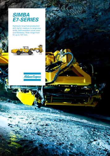
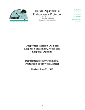
Executive SummaryThis report summarizes the findings of Phase 1 of an American Petroleum Institute (API) Oil SpillResearch and Development (R&D) Project to evaluate Current Practice and Prospective DevelopingTechnologies for the Detection and Delineation of Subsurface Oil in Sediment Shorelines. This Phase 1component of the project defines current practices and identifies selected developing technologies whichpromise to improve on the existing survey methods.Current practice consists primarily of field surveys based on visual observations in excavated pits andtrenches, in some cases supplemented by core samples and materials produced by water jet probes.These procedures can be labor intensive and time consuming, particularly when large areas are involvedor repetitive surveys are necessary. In addition, typically, current practices rely on small horizontalsamples, which may not be adequate to detect or define subsurface oil if the distribution is discontinuous.Developing technologies have a real potential to provide procedures that can either accelerate thecollection of subsurface data or allow for continuous horizontal detection and delineation.Attributes of the basic current and developing technology strategies, in terms of horizontal delineation,vertical delineation, survey speed, description of oil characteristics, and relative costs are summarized inTable E-1. Analysis of these attributes strongly suggests that no single technique is likely to be applicableto all situations that may be encountered and a combination of current practice and developingtechnology (green boxes) may be effective in providing better subsurface resolution at a quicker rate andwith a more efficient commitment of resources.This review promotes the opinion that efforts should continue to improve the efficiency of existing tacticsand development of new technologies. The combined application of these tactics can significantly reducethe reliance on time-consuming practices, improve overall data quality and accelerate the collection ofdata. Some of the developing technologies identified herein (especially use of service dogs,electromagnetic, and surface vapor measurements) show significant potential for achieving operationalstatus with minimal additional testing and trials and so represent a realistic potential for short-term(months to years), high value gains. The development of new technologies can proceed either throughadditional research or by trial applications on real-world events.The results of this Phase 1 study form the basis for Phase 2 studies which include a “Field Guide forSubsurface Oil Detection and Delineation in Shoreline Sediments” (API Technical Report 1149-2, 2013)and a report which will provide recommendations for R&D studies to improve and demonstratedeveloping technologies.v
Table E-1Attributes of Subsurface Oil Survey StrategiesExisting ProceduresATTRIBUTESExcavationCoresDeveloping Technology (Horizontal)Delineation(Vertical)Survey SpeedOil CharacterRelative Cost Green indicates a favorable application; Yellow indicates that the strategy may be effective, depending on circumstances, and Red indicates important limitations or “not applicable”.viGeophysicalSurfaceGas
Contents1.0Introduction . 12.0Phase 1 Objectives . 23.0Background Information on Subsurface Oil . 23.1Data Requirements . 23.2Subsurface Oil on Sediment Shorelines . 33.3Oil Distribution . 43.4Oil Characteristics . 53.5Beach and Sediment Character . 74.0Historical and Current Practice . 74.1General. 74.2Geographical Positioning Systems (GPS) . 84.2.1 General . 84.2.2 Hand Held GPS . 84.2.3 Beach Profiles . 84.3Pits and Trenches . 104.3.1 Pits . 114.3.2 Trenches . 144.3.3 Shallow-water Snorkel Observations . 174.4Core Sampling. 184.4.1 Hand Coring . 184.4.2 Auger and Direct Push Coring . 204.4.3 Vibratory Coring . 214.5Water Jet Probes . 224.6Ultra Violet (UV) Fluorescence (Hand Held) . 235.0Developing Technologies . 255.1General. 255.3Push Probe Observations and Sampling . 285.4Hydrocarbon Gas Detectors (Ground Level Remote Sensing) . 295.5Geophysical Methods . 315.5.1 Ground Penetrating Radar (GPR) . 315.5.2 Electromagnetic (EM) Profiling . 325.5.3 Electrical Resistivity (ER) Profiling/Imaging . 346.0Summary of Current and Developing Practice . 356.1Current Practice . 356.2Developing Technologies . 407.0Conclusions and Recommendations . 437.1Conclusions . 437.2Recommendations . 437.2.1 Improvements to Existing Practices . 437.2.2 Recommendations for Further R&D . 447.2.3 Field Trials and Demonstrations . 448.0References . 44vii
List of TablesTable E-1Attributes of Subsurface Oil Survey Strategies . viTable 4-1Example of a Design for a Point Sample (Pit, Auger, or Coring) Survey . 13Table 6-1Subsurface Detection Techniques Matrix: Current Practices . 37Table 6-2Current Practices: Potential Environmental Impacts, Costs, Pros and Cons . 38Table 6-3Subsurface Oil Detection Techniques Matrix . 41Table 6-4Developing Technologies: Environmental Impacts, Costs, Pros and Cons . 42List of FiguresFigure 4.1GPS Satellite Survey Equipment . 9Figure 4.2Combination of Time-series Beach Profile Data and Pit Information . 9Figure 4.3Observation Pit Showing Scraped Side Wall . 11Figure 4.4Pit Excavation Using Power Auger . 12Figure 4.5Typical Observation Trench . 14Figure 4.6Mechanically-excavated Pit, and Across-beach Trenches Using Track Hoe . 16Figure 4.7Snorkel SCAT – Sampler and Data Logger . 17Figure 4.8Manual Tube Sampler (Clam Gun). 19Figure 4.9Hand Operated Bucket or Sand Auger . 19Figure 4.10Tractor Mounted Small Hollow-stem Auger . 20Figure 4.11Portable Vibracore Device with Extraction Equipment . 21Figure 4.12Water Jet Probe . 23Figure 4.13UV Detection of Oil . 25Figure 5.1Service Dog and Handler on Field Trials in Norway . 27Figure 5.2Representative Push Probe Sampling Equipment. Small Push Probe Unit (left) andProbe/Instrumentation (right) . 28Figure 5.3Remote Gas Sensing Technology. Real Time Plot of Vehicle Mounted Gas Detector –Brown Spikes Indicate High Gas Levels. Equipment Can Monitor Multiple Gases. . 30Figure 5.4Ground Penetrating Radar, Configured for Beach Operations . 31Figure 5.5EM (Terrain Conductivity) Measurement . 33Figure 5.6Electrical Resistivity Instrumentation. 35viii
Subsurface Oil Detection and Delineation in Shoreline SedimentsPhase 1—Final Report1.0IntroductionOil deposited on shorelines during oil spill events can penetrate into sediments, be mixed with underlyingsediments, and/or be buried by natural shoreline processes. The resulting subsurface accumulations canconsist of a continuous layer or layers of solid or emulsified oil, oil-saturated sediments, or scattereddiscontinuous deposits. Subsurface oil is also subject to reworking and re-deposition, depending on thecharacter of the substrate and local wave and tidal energy conditions.Field surveys to detect, delineate and understand the characteristics of subsurface oiling are essential inthe development of shoreline treatment end points and cleanup plans. Survey techniques that have been,and are currently utilized for this purpose, focus primarily on excavations. Excavations provide trainedobservers with the opportunity to visually assess and document both vertical and horizontalcharacteristics of subsurface oil. Other data collection tactics have been tested over the years, and somecontinue to be used, although most do not allow for the diversity of observations that can be obtainedfrom excavations.Time is of the essence in a spill response in order to remove oil from shorelines before it can beremobilized or buried. The quicker field survey data can be collected and assessed, the faster cleanupplans can be developed and implemented. Faster methods of subsurface data collection are desirable. Inaddition, current strategies only provide a relatively small sample of the distribution and character ofsubsurface oil deposits. Better resolution of subsurface oiling is desirable.Based on technological advances and response experience over the last decade, a variety of optionshave emerged that demonstrate significant potential for improving the state-of-the-art in shorelineprotection and cleanup. Recognizing this factor, the API initiated an Oil Spill R&D Program to improve theoverall capabilities for the Protection and Cleanup of Shorelines. One component of this effort addressesthe improvement of shoreline surveys techniques for the detection and delineation of subsurface oil onsediment shorelines. The effort is divided into three phases: Phase 1: Description of current practice and identification of promising detection techniques (thisreport); Phase 2: Development of a “Field Guide to the Detection and Delineation of Subsurface Oil inShoreline Segments”, based on current technology and practices, and assessment of prospectivenew technologies, including recommendations for R&D studies appropriate to advance theapplication of these options; and Phase 3: Consideration of laboratory and field tests/trials to develop and verify the applicability ofhigh potential subsurface oil detection techniques (“Proof of Concept”).There have been significant advances in technology over the past decade and undoubtedly there existtools or techniques that may have an application to detect or delineate subsurface oil that are not coveredin this review. Many ideas were evaluated during the Deepwater Horizon response as part of theAlternative Response Technologies (“ART”) program, some of which involved oil detection on shorelinesand some of which were field tested, such as a laser fluorometer to detect sunken oil in shallow water1
2API TECHNICAL REPORT 1149-1(Cortez, 2011). Technology will continue to improve and there is a reasonable expectation that newstrategies and tactics will evolve in the coming years. This study is one step in that evolutionary process.This review focuses on those classes of developing technology which promise short-term operationalapplication to emergency response detection of spilled oil incorporated in shoreline sediments, with theultimate goals of significantly reducing the reliance on existing time-consuming practices, improvingoverall data quality and accelerating the collection of data.2.0Phase 1 Objectives Identify and document current best practices for the detection and delineation of subsurface oil insediment shorelines. Identify developing technologies that have demonstrated the potential to more effectively, in time andspace, detect and delineate subsurface oil in shoreline sediments (in the context of information andpresentations necessary to support emergency response efforts). Establish a framework within which research can be implemented to progress the highest potentialalternative technologies.3.03.1Background Information on Subsurface OilData RequirementsThe objective of this study is to identify tactics and technologies that can support emergency responseoperations. Spill Management Teams (SMTs) require an appropriate level of knowledge regarding thelocation, extent and character of surface and subsurface oil on shorelines to design, manage, and controlcleanup operations. As conditions can be expected to change with time, repeated situational surveys andupdates are typically necessary. To be useful, information must be available on a near real-time basis.Historical (and current) practice for subsurface oil detection and delineation, and for the monitoring ofcleanup, has relied heavily on visual observations. Although subsurface visual assessments typicallyprovide adequate levels of information to support operations, this strategy is usually slow and laborintensive, particularly with chronic reoiling and dynamic shorelines. Other subsurface observation ordetection and delineation strategies have been applied to expedite subsurface observations with varyingdegrees of success. Technological developments in the last decade have provided the opportunity toimprove current survey tactics as well as a variety of new and promising instruments and techniques.Current shoreline subsurface detection and delineation practice in the US has generally adopted a surveymethodology formalized during the 1989 T/V Exxon Valdez oil spill response. This methodology, theShoreline Cleanup Assessment Technique (SCAT) procedure, allows for the standardized and systematicdescription of shoreline oiling conditions, both on the surface and in subsurface sediments (NOAA, 2000;Owens and Sergy, 1994, 2000). The SCAT observations are intended to be used to develop shorelinetreatment recommendations for consideration by the SMT and are used for: Development of treatment or cleanup end points; Monitoring and adjustment of cleanup tactics; Net environmental benefit analyses (NEBA); Monitoring of cleanup effectiveness;
SUBSURFACE OIL DETECTION AND DELINEATION IN SHORELINE SEDIMENTS Inspections to verify that end points have been achieved; and Long-term recovery monitoring.3A basic assumption of this study is that the SCAT procedure, or its equivalent, will continue to be used tosupport shoreline cleanup decisions and operations. To function effectively within the framework of anemergency response operation, and the continually changing environmental and oiling conditions,situational data must be easily and quickly obtained and updated. In accomplishing this strategy, SCATrelies on the examination of visual information and documentation using trained observers. Thesubsurface component of this process, in particular, typically is labor intensive and time consuming.In an evaluation of modifications to existing tactics, or an evaluation of new strategies, tactics and/ortechnologies, the following attributes should be considered: Scope: Individual tactics may not collect all of the required data. Combinations of existing anddeveloping tactics are acceptable as long as they contribute to improve of the speed, quality andeconomics of data collection; Availability: Any necessary equipment, trained operators and/or other support services should bereadily available; Calibration: Calibration requirements should be minimal and, preferably, field rather than laboratoryprotocols; Data Turn-around Time: Observations are extremely time sensitive and should be available to theSMT on a near real-time basis (i.e. a time scale of days). Immediate data processing andpresentation of summary information is crucial to the decision process; Delineation of Extent: Sufficient detail should be provided to delineate the extent and the distributionof subsurface oil deposits both horizontally and vertically. This information may include: depth andthickness of oil or oiled sediment layer(s), characteristics and distribution of oil within those layer(s),and properties of shoreline sediments (grain size, mineralogy, water content/depth to beachgroundwater, presence of burrows, sediment bearing capacity, etc.); Detection Levels: Detection levels must be consistent with the requirements of each situation. At aminimum, observations should be consistent with SCAT definitions (typically visual). Some promisingtechnologies can offer much higher detection levels. In these cases, speed, reliability and cost factorsshould be considered; Location Control (vertical and horizontal): Precise positioning is essential in all surveys. Currentpractice increasingly relies upon GPS positioning/tracking equipment and GIS data management.High precision GPS and real-time data reduction are desirable (see Section 4.2).3.2Subsurface Oil on Sediment ShorelinesSpilled oiled can be incorporated in shoreline sediments by a variety of mechanisms that include: Fluid oil deposited on the shoreline surface may soak directly into underlying sediments. This typicallyoccurs with oils that have a low viscosity, such as distillate fuels and some fresh, light crude oils.Penetration into the sediments is dependent on: oil viscosity, sediment grain size (porosity), water
4API TECHNICAL REPORT 1149-1content, degree of sediment compaction, and factors such as presence of biogenic pathways (animalburrows). Normally, vertical penetration of oil stops at the beach groundwater surface. If there issufficient available oil, the entire overlying zone may be saturated with oil and there may be a floatinglayer on the beach surface. A similar effect may occur when solid or viscous oil deposited on thesurface is heated by the sun and decreases in viscosity sufficiently to migrate vertically. The lattereffect is common when oil is deposited or stockpiled in the supratidal zone; Floating oil frequently is deposited on shorelines in discontinuous, irregular patterns in the swashzone or as scattered tar balls or residue accumulations; Oil deposited on the surface can be covered (buried) by wind-blown clean sediment or clean sandthat is deposited by natural onshore or along-shore processes (accretion). Multiple layering withdepth is possible; Surface deposits of oil can be covered by sand when dunes collapse during storms; Oil deposited on shoreline surfaces can be mixed with clean underlying or adjacent sediments bywave action and alongshore transport and can be re-deposited at depth and/or in adjacent locations.Downward mixing of oil may be deeper than the groundwater water level. The development ofmultiple oil layers is possible; Surface and subsurface oiling can coexist; Oil may flow or fall into animal burrows.3.3Oil DistributionOil on the surface or within sediments is unlikely to have a regular distribution. In most cases, oil isdeposited on the mid- and upper-intertidal zones in irregular patterns by wave action, storm surges, andother processes which result in varying concentrations of surface oil. Burial processes add a verticaldimension to this irregular distribution. Understanding this typical irregular distribution pattern is critical tothe design and assessment of detection equipment and evaluation techniques.The SCAT manual (Owens and Sergy, 2000) defines the subsurface oiled zone as “the vertical width orthickness of the oiled sediment layer when viewed in profile by digging a pit or trench.” Standard SCATterminology for describing subsurface oil distribution includes: Saturated(Continuous: 91–100 %) Layers(Broken: 51–90 %) Patchy(11–50 %) Sporadic( 10 %) Multiple layers Depth of over burden Water level
SUBSURFACE OIL DETECTION AND DELINEATION IN SHORELINE SEDIMENTS5SCAT also defines specific characteristics of subsurface oil. These characteristics include: Subsurface Asphalt Pavement (SAP): cohesive mixture of weathered oil and sediment situatedcompletely below a surface sediment layer; Oil-filled Pores (OP): pore spaces in the sediment matrix that are completely filled with oil; oftencharacterized by oil flowing out of the pores when disturbed; Partially Filled Pores (PP): pore spaces filled with oil, but generally does not flow out when exposedor disturbed; Oil Residue as a Cover ( 0.1–1.0 cm thick) or Coat (0.01–0.1 cm) (OR) of oil on sediments and/orsome pore spaces partially filled with oil. Cover/Coat can be scratched off easily with fingernail; Oil Film or Stain ( 0.01 cm thick) (OF) of oil residue on the sediment surfaces. Non-cohesive.Cannot be scratched off easily on coarse sediments; Trace (TR): discontinuous film or spots of oil on sediments, or an odor or tackiness with no visibleevidence of oil; and No Oil (NO): no visible or apparent evidence of oil.It is anticipated that equipment and techniques described or resulting from this study would be used insupport of SCAT surveys.3.4Oil CharacteristicsCrude oil and petroleum products exhibit a wide variety of properties which influence their persistence,movement through the environment, and their detection, monitoring, and cleanup requirements. Onceexposed to the environment, these properties can be expected to: (a) differ from MSDS productspecifications, unless the oil is very fresh; and (b) continually change (often significantly) over time asweathering and other processes proceed.Oil properties relevant to the detection, delineation and characterization of subsurface oil, and thedevelopment of response strategies, include: Density: The density of crude oil and products is dependent on their composition and temperature. Oilwill sink when the density is greater than water and float if it is less. Oil density will increase asevaporation and other weathering processes occur, and some oils that initially float may ultimately sink; Pour Point: Pour point is the temperature below which oil will not flow. Many crude oils have pourpoints that are near or at ambient temperature, with the effect that they can change from liquid tosolid and back depending on the ambient temperature range. Pour point can be expected to changeas the oil weathers; Viscosity: Viscosity is a measure of the resistance of a fluid that is being deformed by either shear ortensile stress, and may be though
the improvement of shoreline surveys techniques for the detection and delineation of subsurface oil on sediment shorelines. The effort is divided into three phases: Phase 1: Description of current practice and identification of promising detection techniques (this report); Phase 2: Development of a "