Transcription
Dual Fuel RangeInstallation GuideSPECIFICATIONS, INSTALLATION,AND MORE
Dual Fuel RangeContents3Dual Fuel Range4Safety ootingFeatures and specifications are subject to change at anytime without notice. Visit wolfappliance.com/specs for themost up-to-date information.Important NoteTo ensure this product is installed and operated as safelyand efficiently as possible, take note of the following typesof highlighted information throughout this guide:IMPORTANT NOTE highlights information that is especiallyimportant.CAUTION indicates a situation where minor injury or product damage may occur if instructions are not followed.WARNING states a hazard that may cause serious injury ordeath if precautions are not followed.IMPORTANT NOTE: Throughout this guide, dimensions inparentheses are millimeters unless otherwise specified.IMPORTANT NOTE: Save these instructions for the localelectrical inspector.2 Wolf Customer Care 800.222.7820
Dual Fuel RangeProduct InformationImportant product information, including the model andserial number, are listed on the product rating plate. Therating plate is located on the bottom of the control panel,at the far right, just above the oven door. Refer to theillustration below.If service is necessary, contact Wolf Factory CertifiedService with the model and serial number. For the name ofthe nearest Wolf Factory Certified Service or for questionsregarding the installation, visit the Product Support sectionof our website, wolfappliance.com, or call Wolf CustomerCare at 800-222-7820.RATING PLATERating plate locationwolfappliance.com 3
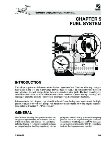
Safety PrecautionsIMPORTANT INSTRUCTIONSWARNINGA child or adult can tip this appliance and bekilled.Verify the anti-tip device has been properlyinstalled and engaged. Ensure the anti-tipdevice is re-engaged when this appliance ismoved. Refer to the illustrations below forhow to verify correct installation.Do not operate this appliance without theanti-tip device in place and engaged. Failureto do so can result in death or serious burnsto children or adults.To reduce the risk of burns, do not move thisappliance while hot.11/2"(38) –1 7/8"(48)ANTI-TIPDEVICEAnti-tip device location4 Anti-tip device engagedWolf Customer Care 800.222.7820 This appliance is equipped with casters on twoor more legs and must be installed on 1/8" (3)thick commercial grade vinyl composition floorfinishing materials or equivalent. This appliance is not approved for downwardairflow ventilation or air curtain equivalent.
SpecificationsInstallation RequirementsElectrical RequirementsIMPORTANT NOTE: When installing against a combustiblesurface, a minimum 10" (254) riser is required for a 36" dualfuel range with charbroiler or griddle and all 48" and 60"models. Follow all minimum clearances to combustiblesurfaces shown in the illustration on page 7.Installation must comply with all applicable electricalcodes.Locate the electrical supply flush with the wall or floorand within the shaded area shown in the illustration onpage 7. A separate circuit servicing only this appliance isrequired.If a power supply cord is used, the cord must be designated for use with ranges and rated for 240 V, 30 or 50amps (refer to the chart below), and must include 3 or 4conductors. A 4-conductor cord is required for installations where grounding through the neutral is prohibited.Performance may be compromised if the electrical supplyis less than 240 volts.ELECTRICAL REQUIREMENTS—SINGLE OVENElectrical Supplygrounded, 240/208 VAC, 60 HzService30 amp dedicated circuitTotal Amps21Max Connected Load5.2 kWELECTRICAL REQUIREMENTS—DOUBLE OVENElectrical Supplygrounded, 240/208 VAC, 60 HzService50 amp dedicated circuitTotal Amps42.5Max Connected Load10.2 kWRATING PLATERating plate locationwolfappliance.com 5
SpecificationsGas SupplyInstallation must comply with local codes, or in theabsence of local codes, with the National Fuel Gas Code.Locate the gas supply within the shaded area shown in theillustration on the following page.The range is equipped for use with natural or liquid propane (LP) gas. The product rating plate has informationon the type of gas that should be used. For rating platelocation, refer to the illustration below. If this informationdoes not agree with the type of gas available, check withthe local gas supplier. The gas pressure regulator is builtinto the unit.GAS REQUIREMENTSNATURAL GASWCSupply Pressure5" (12.5 mb)Min Line Pressure7" (17.5 mb)Max Regulator Pressure14" (34.9 mb), .5 psi (3.5 kPa)LP GASWCSupply Pressure10" (25 mb)Min Line PressureMax Regulator Pressure11" (27.4 mb)14" (34.9 mb), .5 psi (3.5 kPa)The range must be connected to a regulated gas supply.The supply line must be equipped with an approved external gas shut-off valve located near the range in an accessible location. Do not block access to the shut-off valve.Refer to the illustration below.A gas supply of 3/4" (19) ID line must be provided to therange. If local codes permit, a certified, 3' (.9 m) long, 1/2" (13)or 3/4" (19) ID flexible metal appliance connector is recommended to connect the units 1/2" NPT female inlet to thegas supply line. Pipe joint compounds suitable for use withnatural or LP gas should be used.The appliance and its shut-off valve must be disconnectedfrom the gas supply piping system during any pressuretesting of the system at test pressures in excess of .5 psi(3.5 kPa). The appliance must be isolated from the gassupply piping system by closing its individual manual shutoff valve during any pressure testing of the system at testpressures equal to or less than .5 psi (3.5 kPa).Wolf natural gas ranges will function up to 10,250' (3124 m)in altitude without adjustment and LP gas ranges will function up to 8,600' (2621 m). If the installation exceeds theseelevations, contact an authorized Wolf dealer for a highaltitude conversion kit.RATING PLATESHUT-OFF VALVEOPEN POSITIONTO APPLIANCERating plate locationGas shut-off valve6 Wolf Customer Care 800.222.7820GAS SUPPLY
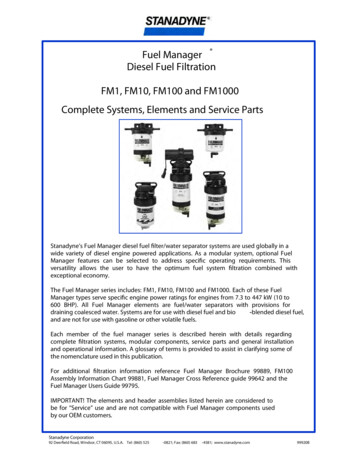
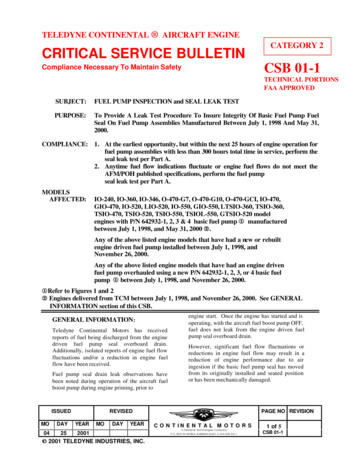
SpecificationsDual Fuel RangeINSTALLATION13"18"30" (762) TO 36" (914)(330)(457)TO BOTTOM OFVENTILATION HOOD*6"(152)WOPENING WIDTHELECTRICALAND GAS IN‘A’ LOCATIONONLY2"(51)8 1/2"A4 7/8"(124)SIDE VIEWE(216)GFRONT VIEW*Without ventilation hood, 36" (914) minimum clearance countertop to combustible materials, 44" (1118) for charbroiler.NOTE: Shaded area above countertop indicates minimum clearance to combustible surfaces,combustible materials cannot be located within this area.For island installation, 12" (305) minimum clearance back of range to combustible rear wall above countertop.OPENING WIDTHWA30" Range30" (762)101/4" (260)36" Range36" (914)161/4" (413)48" Range48" (1219)181/4" (464)60" Range60" (1524)181/4" (464)wolfappliance.com 7
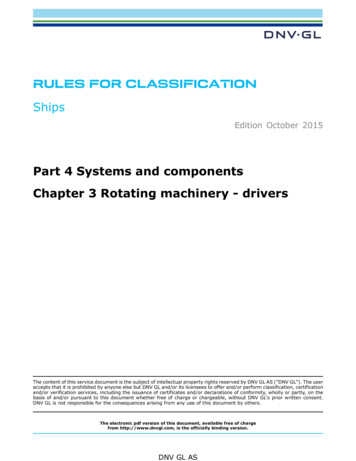
InstallationPreparationPlacementBefore moving the range, protect any finished flooring andsecure the oven door(s) closed to prevent damage.The range has rear casters which allow for easy movementby lifting the front of the unit. Do not lift or carry the rangeby the oven door handle.OVEN DOOR REMOVALUse an appliance dolly to move the range near the opening. Place the appliance dolly on the side or back to prevent damage. Remove and recycle packing materials. Donot discard the anti-tip bracket supplied with the range.To lighten the load or to fit through a doorway, the ovendoor(s) can be removed. Remove only if necessary. Do notremove the griddle or any other component. Door removalshould be done only by a certified installer or servicetechnician. Do not lift or carry the oven door by the doorhandle.To remove, open the door completely. Rotate both hingelocks forward to the open position, remove the screwclosest to the hinge on both sides of the door, and pull thedoor forward. Refer to the illustration below.To reinstall, slide the door onto the hinges. Rotate thehinge locks back completely and install the screws.If a riser has been specified, refer to the installation instructions packaged with the riser. The riser must be installedbefore the range is installed.LevelingRaise the range to its desired height by adjusting the frontlegs and rear casters. Use a 3/4" socket to adjust the rearcasters. The front legs can be adjusted by rotating the legclockwise to raise and counterclockwise to lower.IMPORTANT NOTE: For 48" and 60" models, equallydistribute the load to all three front legs and rear casters.SCREWHINGELOCKOven door removal8 Wolf Customer Care 800.222.7820
InstallationAnti-Tip BracketTo prevent the range from tipping forward, the anti-tipbracket must be installed. To ensure the anti-tip boltengages the bracket, refer to the illustration below todetermine proper placement.ANTI-TIP BOLT ADJUSTMENTOnce the bracket is secure, adjust the anti-tip bolt so thetop of the washer is 11/2" (38) to 17/8" (48) from the floor.Slide the range into the opening and verify the anti-tip boltis engaged. Refer to the illustration below.INSTALL BRACKETDrywall application: After properly positioning the anti-tipbracket, mark the holes, then use a Phillips screwdriveror a low rpm power drill to drive the wall anchor into thesurface of the wallboard until flush. Pre-drill the holes ifneeded. For hard wallboard or double-board construction, use a 1/4" drill bit. For solid plaster, use a 7/16" drill bit.Use the provided #8 screws and flat washers to fasten thebracket to the wall.Wood floor application: After properly positioning the antitip bracket, drill 3/16" (5) pilot holes through the floor. Usethe provided #12 screws and flat washers to secure thebracket to the floor.Concrete floor application: After properly positioningthe anti-tip bracket, drill 3/8" (10) holes into the concretea minimum of 11/2" (38) deep. Use the provided 3/8" wedgeanchors to secure the bracket to the floor.11/2"(38) –1 7/8"(48)Anti-tip bolt engagedANTI-TIPBRACKET61/4"(159)Anti-tip bracket locationwolfappliance.com 9
InstallationElectrical ConnectionGas Supply ConnectionThe terminal block on the back of the range allows for a3-wire or 4-wire installation. Remove the terminal blockcover to expose the screws with corresponding numbers.Route the wires through the strain relief and to the terminal block.All connections to the gas piping must be wrench-tightened. Do not overtighten or allow pipes to turn whentightening.THREE-WIRE INSTALLATION1Move the metal ground strap to positions one and two.Refer to the illustration below.2Connect green/ground to position one.3Connect red/L2 to position three.4 Connect black/L1 to position four.5Tighten the screws on the strain relief and install theterminal block cover.FOUR-WIRE INSTALLATION1Remove the metal ground strap.2Connect green/ground to position one.3Connect white/neutral to position two.4 Connect red/L2 to position three.5Connect black/L1 to position four.6 Tighten the screws on the strain relief and install theterminal block cover.6655443REMOVE211Three- and four-wire10 32Three-wire onlyWolf Customer Care 800.222.7820INSTALLIf a flexible metal connector is used, verify it is not kinked,then attach the gas supply line to the gas inlet on therange. Open the valve and check for leaks by placing aliquid detergent solution onto all gas connections.Bubbles around the connections indicate a gas leak.If a leak appears, close the shut-off valve and adjust theconnections.
InstallationDoor AlignmentTroubleshootingTo adjust the door, follow these steps:IMPORTANT NOTE: If the range does not operate properly,follow these troubleshooting steps:1Remove the skirt by extracting the screws.2Open the door, and loosen the nut. Refer to theillustration below.3Close the door, and turn the screw clockwise to raiseand counterclockwise to lower the door.4 Open the door, and tighten the nut.5Close the door, and reinstall the skirt. Verify electrical power is supplied to the range. Verify the gas supply shut-off valve is in the openposition. If the range does not operate properly, contact WolfFactory Certified Service. Do not attempt to repair therange. Wolf is not responsible for service required tocorrect a faulty installation.ADJUSTMENTSCREWNUTSKIRTDoor alignmentSub-Zero, Sub-Zero & Design, Sub-Zero & Snowflake Design, Dual Refrigeration, The Living Kitchen, Great American Kitchens The Fine Art of Kitchen Design, Wolf, Wolf &Design, Wolf Gourmet, W & Design, red colored knobs, Cove, and Cove & Design are registered trademarks and service marks of Sub-Zero Group, Inc. and its subsidiaries.All other trademarks are property of their respective owners in the United States and other countries.wolfappliance.com 11
Estufa de energía dualContenido3Estufa de energía dual4Precauciones de seguridad5Especificaciones8Instalación11Solución de problemasLas características y especificaciones están sujetas acambios sin previo aviso. Visite wolfappliance.com/specspara obtener la información más actualizada.Aviso importantePara garantizar que este producto se instale y opere dela forma más segura y eficiente posible, tome nota de lossiguientes tipos de información resaltada en este manual:AVISO IMPORTANTE señala la información que esespecialmente importante.PRECAUCIÓN indica una situación en la que se puedensufrir heridas leves o provocar daños al producto si no sesiguen las instrucciones.ADVERTENCIA indica peligro de que se produzcan heridasgraves o incluso la muerte si no se siguen las precauciones.AVISO IMPORTANTE: En toda esta guía, las dimensionesentre paréntesis son milímetros, a menos que seespecifique lo contrario.AVISO IMPORTANTE: Guarde estas instrucciones para elinspector eléctrico local.2 Atención al cliente de Wolf 800.222.7820
Estufa de energía dualInformación del productoLa información importante del producto, incluidos elmodelo y el número de serie de la unidad, se encuentraen la placa de datos del producto. La placa de datos seencuentra en la parte inferior del panel de control, en elextremo derecho, justo por encima de la puerta del horno.Consulte la siguiente ilustración.Si es necesario realizar algún servicio, póngase en contactocon el servicio certificado de fábrica de Wolf y tenga amano el modelo y el número de serie. Para obtener losdatos del centro de Servicio certificado de fábrica de Wolfmás cercano o si tiene preguntas acerca de la instalación,visite la sección de soporte del producto en nuestra páginade Internet wolfappliance.com; o bien, llame a la línea deatención al cliente de Wolf al 800-222-7820.PLACA DE DATOSUbicación de la placa de datoswolfappliance.com 3
Precauciones de seguridadINSTRUCCIONES IMPORTANTESADVERTENCIASi un niño o un adulto jalan el electrodomésticoeste puede volcarse y causarles la muerte.Compruebe que el dispositivo antivuelcohaya sido instalado y esté enganchadocorrectamente. Asegúrese de volver aenganchar el dispositivo antivuelco después decambiar el electrodoméstico de lugar. Consultelas ilustraciones siguientes para saber cómocomprobar su instalación correcta.No opere este electrodoméstico sinel dispositivo antivuelco en posición yenganchado. No seguir esta instrucción puederesultar en la muerte o en graves quemadurasen niños o adultos.Para reducir el riesgo de quemaduras, no muevael electrodoméstico mientras está caliente.11/2"(38) –1 7/8"(48)DISPOSITIVOANTIVUELCOUbicación del dispositivoantivuelco4 Dispositivo antivuelcoenganchadoAtención al cliente de Wolf 800.222.7820 Este electrodoméstico está equipado conruedas en dos o más patas y debe ser instaladosobre pisos de grado comercial con 1/8" (3) degrosor, hechos de materiales compuestos convinilo o equivalentes. Este electrodoméstico no ha sido aprobadopara la ventilación con flujo de aire dirigidohacia abajo o una cortina de aire equivalente.
EspecificacionesRequisitos de instalaciónRequisitos eléctricosAVISO IMPORTANTE: al realizar la instalación contra unasuperficie combustible, se requiere una tarima con alturamínima de 10" (254) para una estufa de energía dual de 36"con parrilla o plancha y para todos los modelos de 48" y60". Mantenga todos los espacios mínimos a las superficiescombustibles, como se muestra en la ilustración de lapágina 7.La instalación debe cumplir con todos los códigoseléctricos vigentes.Coloque el suministro eléctrico a ras con la pared oel piso y dentro del área sombreada que se muestraen la ilustración de la página 7. Se necesita un circuitoindependiente que le suministre electricidad únicamente aeste electrodoméstico.Si se utiliza un cable de alimentación, el cable debe haberconcebido para uso con estufas y tener capacidad para240 V, 30 o 50 amperes (consulte la tabla siguiente), ydebe incluir 3 o 4 conductores. Se requiere un cable de 4conductores para instalaciones en las que está prohibidorealizar la conexión a tierra a través del cable neutro.El rendimiento puede verse comprometido si el suministroeléctrico es menor a 240 voltios.REQUISITOS ELÉCTRICOS—HORNO SENCILLOSuministro eléctrico Con conexión a tierra, 240/208 V CA, 60 HzServicioCircuito dedicado de 30 amperesTotal de amperes21Carga máxima conectada5.2 kWREQUISITOS ELÉCTRICOS—HORNO DOBLESuministro eléctrico Con conexión a tierra, 240/208 V CA, 60 HzServicioCircuito dedicado de 50 amperesTotal de amperesCarga máxima conectada42,510.2 kWPLACA DE DATOSUbicación de la placa de datoswolfappliance.com 5
EspecificacionesSuministro de gasLa instalación debe cumplir con los códigos locales, o enausencia de códigos locales, con el Código Nacional deGas Combustible.Localice el suministro de gas en la zona sombreada que semuestra en las ilustración de la página siguiente.La estufa está equipada para su uso con gas licuado (LP) opropano natural. La placa de datos del producto contieneinformación sobre el tipo de gas que se debe utilizar. Paraubicar la placa de datos, consulte la siguiente ilustración. Siesta información no coincide con el tipo de gas disponible,consulte con el proveedor de gas local. El regulador depresión de gas está incorporado a la unidad.REQUISITOS DEL GASGAS NATURALCOLUMNA DE AGUAPresión de suministro5" (12.5 mb)Presión mínima de la líneaPresión máxima delreguladorGAS LP7" (17.5 mb)14" (34.9 mb), .5 psi (3.5 kPa)COLUMNA DE AGUAPresión de suministro10" (25 mb)Presión mínima de la líneaPresión máxima delregulador11" (27.4 mb)14" (34.9 mb), .5 psi (3.5 kPa)La estufa debe conectarse a un suministro de gas regulado.La línea del suministro debe estar equipada con una llavede paso externa aprobada para gas ubicada cerca de laestufa en un lugar accesible. No bloquee el acceso a lallave de paso. Consulte la siguiente ilustración.Se debe proporcionar una línea de suministro de gas3/4" (19) para la estufa. Si el código local lo permite,se recomienda utilizar un conector metálico flexiblecertificado, de 3' (.9 m) de largo, 1/2" (13) o 3/4" (19) dediámetro interior para conectar la entrada NPT hembrade 1/2" de la unidad a la línea de suministro de gas. Debeutilizar compuestos para juntas de tubería aptos para usocon gas natural o gas LP.Debe desconectar el electrodoméstico y la llave de pasodel sistema de tuberías del suministro de gas durantecualquier prueba de presión del sistema a presionesde prueba mayores a 0.5 psi (3.5 kPa). Debe aislar elelectrodoméstico del sistema de tuberías del suministrode gas cerrando manualmente la llave de paso durantecualquier prueba de presión del sistema a presiones deprueba iguales o inferiores a 0.5 psi (3.5 kPa).Las estufas a gas natural de Wolf funcionarán hasta10,250' (3124 m) de altitud sin ajuste y las estufas a gasLP funcionarán hasta 8,600' (2621 m). Si la instalaciónsupera estas elevaciones, póngase en contacto con undistribuidor autorizado de Wolf para conseguir un kit deconversión para regiones altas.PLACA DE DATOSLLAVE DE PASOEN POSICIÓN ABIERTAUbicación de la placa de datosA LA UNIDADSUMINISTRODE GASLlave de paso del suministrode gas6 Atención al cliente de Wolf 800.222.7820
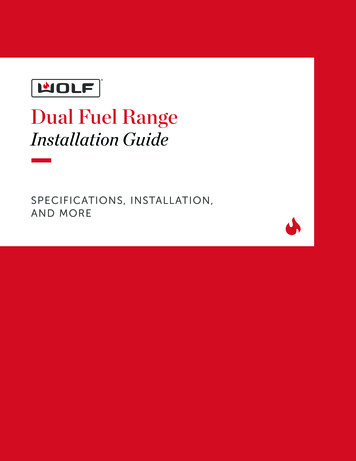
EspecificacionesEstufa de energía dualINSTALACIÓN13"18"(330)(457)30" (762) A 36" (914)A LA PARTE INFERIOR DE LACAMPANA DE VENTILACIÓN*6"(152)WANCHO DE LA ABERTURAELÉCTRICA YDE GAS EN LAUBICACIÓN ‘A’SOLAMENTE2"(51)8 1/2"A4 7/8"(124)VISTA LATERALE(216)GVISTA FRONTAL*Sin campana de ventilación, se requiere una distancia mínima de 36" (914) desde el mostrador hasta los materiales combustibles,y 44" (1118) para la parrilla.NOTA: La zona sombreada sobre el mostrador indica la distancia mínima a las superficies combustibles, los materiales combustiblesno se pueden colocar en esta área.Para instalaciones en islas, se necesita una distancia mínima de 12” (305) en la parte posterior de la estufa a la pared traserainflamable sobre el mostrador.ANCHO DE LA ABERTURAANCHOAEstufa de 30"30" (762)101/4" (260)Estufa de 36"36" (914)161/4" (413)Estufa de 48"48" (1219)181/4" (464)Estufa de 60"60" (1524)181/4" (464)wolfappliance.com 7
InstalaciónPreparaciónColocaciónAntes de mover la estufa, proteja cualquier suelo acabadoy asegúrese de que la(s) puerta(s) del horno esté(n) ycerrada(s) para que no se dañe(n).La estufa tiene ruedas traseras para facilitar sudesplazamiento levantando el frente de la unidad. Noutilice la manija de la puerto de horno para levantar otransportar la estufa.CÓMO QUITAR LA PUERTA DEL HORNOUse una carretilla para electrodomésticos para mover laestufa cerca de la abertura. Para evitar daños, coloque lacarretilla del electrodoméstico en el costado o en la parteposterior. Retire y recicle los materiales de embalaje. Nodeseche el soporte antivuelco suministrado con la estufa.La(s) puerta(s) del horno puede(n) removerse para aligerarla carga o conseguir que pase a través de una puerta. Solodeberá quitarse si es necesario. No retire la plancha nininguno de los otros componentes. El proceso para quitarla puerta del horno debe ser realizado solamente por uninstalador certificado o un técnico de servicio. No utilicela manija de la puerta del horno para levantar la puerta nipara transportarla.Para quitarla, abra la puerta completamente. Gire lospestillos de las dos bisagras hacia adelante a la posiciónabierta, quite el tornillo más cercano a la bisagra en amboslados de la puerta, y a continuación jale la puerta haciadelante. Consulte la siguiente ilustración.Para volver a instalar, deslice la puerta en las bisagras. Girelos pestillos de las bisagras completamente hacia atrás einstale los tornillos.TORNILLOBLOQUEODE BISAGRACómo quitar la puertadel horno8 Atención al cliente de Wolf 800.222.7820Si se ha especificado el uso de una tarima, consulte lasinstrucciones de instalación que vienen con la tarima.Debe instalar la tarima antes de instalar la estufa.NivelaciónPara levantar la estufa a la altura deseada, ajuste las patasdelanteras y las ruedas traseras. Utilice una llave de 3/4" paraajustar las ruedas traseras. Las patas delanteras se puedenajustar girando la pata hacia la derecha para subir y hacia laizquierda para bajar.AVISO IMPORTANTE: Para los modelos de 48" y 60",distribuya la carga equitativamente sobre las tres patasdelanteras y las ruedas traseras.
InstalaciónSoporte antivuelcoPara evitar que la estufa se vuelque hacia el frente, debeinstalarse el soporte antivuelco. Para asegurarse de queel perno antivuelco se acople con el soporte, consultela ilustración de abajo para determinar cómo colocarlocorrectamente.CÓMO AJUSTAR EL PERNO ANTIVUELCOUna vez que el soporte está asegurado, ajuste el pernoantivuelco de manera que parte superior de la arandelaquede a 11/2" (38) a 17/8" (48) del piso. Deslice la estufadentro de la abertura y compruebe que el perno antivuelcoesté enganchado. Consulte la siguiente ilustración.CÓMO INSTALAR EL SOPORTEAplicación en panel de yeso: Después de colocarcorrectamente el soporte antivuelco, marque los orificios,luego utilice un desarmador Philips o un taladro eléctricoa bajas rpm para introducir el anclaje de pared en elpanel de yeso hasta que quede a ras con la superficie.Si es necesario taladre los orificios con anticipación.Para paneles de yeso duro o construcción de dobleplaca, utilice una broca de 1/4". Para yeso sólido, utiliceuna broca de 7/16". Utilice tornillos #8 y arandelas planasproporcionados para sujetar el soporte a la pared.Aplicación en piso de madera: Después de colocarcorrectamente el soporte antivuelco, taladre orificios guíade 3/16" (5) en el piso. Utilice tornillos #12 y arandelas planasproporcionados para asegurar el soporte al piso.11/2"(38) –1 7/8"(48)Perno antivuelco enganchadoAplicación en piso de concreto: Después de colocarcorrectamente el soporte antivuelco, taladre orificiosde 3/8" (10) en el concreto a una profundidad mínima de11/2" (38). Utilice anclajes de cuña proporcionados de3/8" para asegurar el soporte al piso.SOPORTEANTIVUELCO61/4"(159)Ubicación del soporteantivuelcowolfappliance.com 9
InstalaciónConexión eléctricaConexión del suministro de gasEl bloque de terminales en la parte posterior de la estufapermite una instalación de 3 cables o 4 cables. Retirela cubierta del bloque de terminales para exponer lostornillos con los números correspondientes. Guíe loscables a través del liberador de tensión y al bloque determinales.Todas las conexiones a la tubería de gas deben apretarsecon llave. No apriete demasiado ni permita que las tuberíasgiren al apretarlas.INSTALACIÓN DE TRES CABLES1Mueva la banda metálica de conexión a tierra a lasposiciones uno y dos. Consulte la siguiente ilustración.2Conecte verde/tierra a la posición uno.3Conecte rojo/L2 a la posición tres.4 Conecte negro/L1 a la posición cuatro.5Apriete los tornillos en el liberador de tensión e instalela cubierta del bloque de terminales.INSTALACIÓN DE CUATRO CABLES1Quite la banda metálica de conexión a tierra.2Conecte verde/tierra a la posición uno.3Conecte blanco/neutral a la posición dos.4 Conecte rojo/L2 a la posición tres.5Conecte negro/L1 a la posición cuatro.6 Apriete los tornillos en el liberador de tensión e instalela cubierta del bloque de terminales.665544332211Tres y cuatro cables10 RETIREINSTALETres cables solamenteAtención al cliente de Wolf 800.222.7820Si se utiliza un conector de metal flexible, compruebeque no esté doblado y, a continuación, conecte la líneade suministro de gas a la entrada de gas de la estufa. Abrala válvula y revise si hay fugas mediante la colocaciónde una solución de detergente líquido sobre todas lasconexiones de gas. La presencia de burbujas alrededor delas conexiones es indicador de una fuga de gas. Si apareceuna fuga, cierre la llave de paso y ajuste las conexiones.
InstalaciónAlineamiento de la puertaSolución de problemasPara ajustar la puerta, siga los pasos siguientes:AVISO IMPORTANTE: si la estufa no funciona correctamente,siga estos pasos para resolver los problemas:1Para quitar la falda extraiga los tornillos.2Abra la puerta y afloje la tuerca. Consulte la siguienteilustración.3Cierre la puerta y gire el tornillo a la derecha para subiry a la izquierda para bajar la puerta.4 Abra la puerta y apriete la tuerca.5Cierre la puerta y vuelva a instalar la falda. Compruebe que la estufa tiene corriente eléctrica. Compruebe que la llave de paso del suministro de gasse encuentra en posición abierta. Si la estufa no funciona correctamente, póngase encontacto con el centro de servicio autorizado de Wolf.No intente reparar la estufa. Wolf no es responsabledel servicio necesario para corregir una instalacióndefectuosa.TORNILLODE AJUSTETUERCAFALDAAlineamiento de la puertaSub-Zero, Sub-Zero & Design, Sub-Zero & Snowflake Design, Dual Refrigeration, The Living Kitchen, Great American Kitchens The Fine Art of Kitchen Design, Wolf, Wolf &Design, Wolf Gourmet, W & Design, red colored knobs (perillas de color rojo), Cove y Cove & Design son marcas registradas y marcas de servicio de Sub-Zero Group, Inc. ysus filiales. Todas las demás marcas registradas son propiedad de sus dueños respectivos en Estados Unidos y otros países.wolfappliance.com 11
Cuisinière mixteTable des matières3Cuisinière mixte4Précautions de eLes caractéristiques et les spécifications peuventêtre modifiées en tout temps sans préavis. Visitezwolfappliance.com/specs pour obtenir les renseignementsles plus récents.Remarque importantePour s’assurer que ce produit est installé et utilisé en toutesécurité et aussi efficacement que possible, prenez notedes types de renseignement mis en évidence tout au longde ce guide :REMARQUE IMPORTANTE met en évidence desrenseignements qui sont particulièrement importants.MISE EN GARDE indique une situation où une blessuremineure ou des dommages au produit peuvent se produiresi les directives ne sont pas respectées.AVERTISSEMENT décrit un danger qui peut causer uneblessure grave ou la mort si les précautions ne sontpas respectées.REMARQUE IMPORTANTE : Tout au long de ce guide, lesdimensions entre parenthèses sont en millimètres à moinsd’indication contraire.REMARQUE IMPORTANTE : Conservez ces directives pourl’inspecteur en électricité local.2 Service à la clientèle de Wolf 800.222.7820
Cuisinière mixteRenseignements sur le produitDes renseignements importants sur le produit, y comprisles numéros de modèle et de série, se trouvent sur laplaque signalétique du produit. La plaque signalétique estsituée sous le panneau de commande, à l’extrême droite,juste au-dessus de la porte du four. Reportez-vous àl’illustration ci-dessous.Si vous avez besoin de service, communiquez avec leservice Wolf certifié par l’usine avec les numéros demodèle et de série. Pour obtenir le nom du centre deservice Wolf certifié par l’usine le plus près de chez vousou si vous avez des questions concernant l’installation,consultez la section Support technique de notre site Web,wolfappliance.com, ou appelez le service à la clientèle deWolf au 800-222-7820.PLAQUESIGNALÉTIQUEEmplacement de la plaquesignalétiquewolfappliance.com 3
Précautions de sécuritéDIRECTIVES IMPORTANTESAVERTISSEMENTUn enfant ou un adulte peuvent faire basculercet appareil et être tués.Vérifiez que le dispositif antibasculement estcorrectement installé et enclenché. Assurezvous qu
locks forward to the open position, remove the screw closest to the hinge on both sides of the door, and pull the door forward. Refer to the illustration below. To reinstall, slide the door onto the hinges. Rotate the hinge locks back completely and install the screws. Placement The range has rear casters which allow for easy movement