Transcription
Chain Link Fence Manufacturers InstituteProduct ManualCLF-PM0610(revised July, 2011)Table of ContentsHow to Use the Product Manual1Description of Terms2Table 1 - Breaking Strength of Steel Wire3Table 2 -Thickness of ASTM F668 Fabric Polymer Coating3Table 3 - Standard Mesh Sizes and Gauges for Chain Link Fabric4Table 4 - Small Mesh Sizes and Wire Gauges for Metallic Coated Chain Link Fabric5Table 5 - Small Mesh Sizes for Wire Gauges for Polymer Coated Chain Link Fabric6Table 6 - Galvanized Steel Post Dimensions and Strength Characteristics7Table 7 - Guide for Selection of ASTM F 1043 Line Post8DrawingsTypical Fence Section - Top Rail/Trussed Brace Rail with Bottom Tension Wire9Typical Fence Section - Trussed Brace Rail w/Top & Bottom Tension Wire10Typical Fence Elevation – Top Rail/Trussed Brace Rail w/ Bottom Tension Wire11Typical Fence Elevation – Trussed Brace Rail; 3 Stands Barbed Wire w/ Top & Bottom Tension Wire 12Typical Fence Elevation –Top Rail/Trussed Brace Rail 3 Stands Barbed Wire & Bottom Tension Wire 13Typical Swing Gate – Three Strands Barbed Wire (OPTIONAL)14Typical Double Swing Gate – Three Strands Barbed Wire (OPTIONAL)15Single Cantilevered Sliding Gate – Round Posts w/ Barbed Wire (6’ thru 22’ openings)16Single Cantilevered Sliding Gate – Round Posts w/ Barbed Wire (10’ thru 30’)17CLFMI GUIDE FOR SPECIFYING COMMERCIAL, INDUSTRIAL, AND SECURITYCHAIN LINK FENCE AND GATES ( Contract Section 32 31 13)Addendum(Note: For a copy of this specification in Word format please contact CLFMI Headquarters)Copyright 2011.All rights reservedChain Link Fence Manufacturers Institute10015 Old Columbia Road Suite B215Columbia, MD 21046www.chainlinkinfo.org
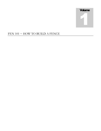
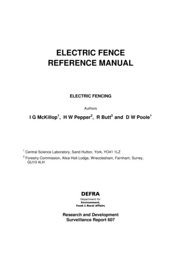
CHAIN LINK FENCE MANUFACTUTERS INSTITUTE PRODUCT MANUAL(CLF‐PM2445)The purpose of this manual is to provide chain link fence technical information for general knowledge,system design or the development of a commercial/industrial/security chain link fence specification.HOW TO USE THE CLFMI PRODUCT MANUALa. Familiarize yourself with the content of the CLFMI product manual.b. The product manual includes drawings of the four standard chain link fence designs plus swinggate, cantilever slide gate and fitting/assembly details.c. Review the different chain link fabric configurations and gauges to ensure the best selection ofthe mesh size and wire gauge for the application.d. Prior to designing a security fence system read the CLFMI “Security Fencing RecommendationsSFR2445”.e. Select the type of fabric for the application; galvanized (ASTM A392), aluminum coated (ASTMA491), zinc ‐5% mischmetal alloy (ASTM F1345) or polymer coated (ASTMF 668).f. Review the framework Dimensions and Strength Characteristics Table # 6 and Guide forSelection of Line Post, Table # 7 to select the post that best suits the application, (ASTM F1043and ASTM F1083). Make sure to take into consideration wind load particularly if the fence is 8 ft.high or greater using 1 in. mesh or less. Use the CLFMI “Chain Link Fence Wind Load Guide forthe Selection of Line Post and Line Post Spacing WLG2445” for a fence requiring a structuralframework design due to wind load.g. For polymer coated fabric or systems choose an ASTM color from ASTM F934.h. Thoroughly review and understand the chain link ASTM standards; those reference above aswell as; chain link terminology (F552), fittings and tie wire (F626), barbed wire (A121 and F665),barbed tape (F1910 and F1911) tension/coil spring wire (A824 and F1644), swing gates (F900),horizontal slide gates (F1184), automated vehicular gates (F2200), and chain link installation(F567).i. The CLFMI manual includes a CSI formatted chain link fence specification, “Commercial,Industrial and Security Chain Link Fence and Gates, Section 32 31 13” for use in designing andspecifying a chain link fence system.j. For light industrial/commercial applications select framework form ASTM F1043 Table 4“Summary of Requirements for Light Industrial/Commercial Fence Framework”.k. All phases of chain link fence installation are covered in detail within the Specification 32 31 13,Part 3.1
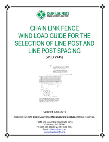
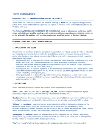
DESCRIPTION OF TERMSA short list of descriptive terms: (See ASTM F552, “Standard Terminology Relating to Chain LinkFencing” for a complete list.)a. Chain link fabric – A fencing material consisting of wire helically wound and interwoven in such amanner as to provide a continuous mesh without knots or ties except in the form of knuckling ortwisting at the top and bottom of the mesh to form the fabric selvage.b. Selvage‐The top and bottom edge finish on woven chain link formed by joining adjacent pairs ofwire pickets. The selvage may be knuckled or twisted.c. Knuckled selvage* refers to bending the adjacent pairs of wire back into a tight loop.d. Twisted selvage* refers to twisting the adjacent pairs of wire together in a close helix of 1 ½machine turns, which is equivalent to three full twists.e. Mesh size – The minimum clear distance between the wires forming the parallel sides of themesh.f. Terminal post – A post to which the chain link fabric is terminated using specific fittings; endpost, corner post, gate post and pull post (a terminal post used to accommodate a grade orplaced at intervals on long stretches of fence).g. Line post‐ Intermediate posts set no greater than 10 feet on center between the terminal posts.h. See drawing Typical Fence Section for details of various fence fittings; tension bar, truss rod,tension band, brace band, rail end and barb arm.KNUCKLE SELVAGE*TWIST SELVAGE**Adapted, with permission from the Annual Book of Standards, copyright ASTM International, 100 Barr Harbor Drive, West Conshohocken, PA192482
TABLE 1BREAKING STRENGTH OF STEEL WIRE6 gauge ‐0.192”[4.88 mm]2170 lbf [9650 N]9 gauge‐ 0.148”[3.76 mm]1290 lbf [5740 N]11 gauge‐ 0.120”[3.05 mm]850 lbf [3780 N]11 ½ gauge‐ 0.113”[2.87 mm]750 lbf [3340 N]12 gauge‐ 0.105”[2.67 mm]650 lbf [2890 N]14 gauge‐ 0.080”[2.03 mm]380 lbf [1690 N]TABLE 2 THICKNESS OF ASTM F668 FABRIC POLYMER COATINGMinimum/MaximumClass 1 & Class 2aClass 2bMinimum @ any point0.015 in. [0.38 mm]0.006 in. [0.15 mm]Maximum @ any point0.025 in. [0.64 mm]0.010 in. [0.25 mm]3
TABLE 3 STANDARD 1” & LARGER MESH SIZES AND GAUGES FOR CHAIN LINK FABRICASTM A392 galvanized, ASTM A491 aluminum coated, ASTM F1345 zinc‐5%aluminum‐mischmetal alloy, ASTM F668 polymer coatedSize of meshGauge*Nominal DiameterRecommended Usage2 1/8” [54 mm]11 ½0.113” [2.87 mm]Residential2” [50 mm]110.120” [3.05 mm]Residential/light commercial2” [50 mm]90.148” [3.76 mm]Residential /commercial/ind.2” [50 mm]60.192” [4.88 mm]Commercial/ind./security1 ¾” [44 mm]110.120” [3.05 mm]Tennis court1 ¾” [44 mm]90.148” [3.76 mm]Heavy commercial/industrial1 ¾” [44 mm]60.192” [4.88 mm]Security1 ¼” [32 mm]110.120” [3.05 mm]Residential/swimming pool1 ¼” [32 mm]90.148” [3.76 mm]Heavy industrial /Security1” [25 mm]110.120” [3.05 mm]Industrial1” [25 mm]90.148” [3.76 mm]Heavy industrial/ Security*polymer coated core wire gauge is specified gauge reference not the coated finished diameter4
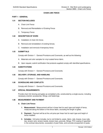
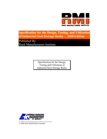
Figure 1. Mesh Dimensions for small security chain link fabric**Mesh Size SHeight HWidth W3/8 in. [9 mm]3/4 in.[19 mm]3/4 in. [19 mm]1/2 in. [13 mm]15/16 in. [24 mm]15/16 in. [24 mm]5/8in. [16 mm]1 1/8 in. [29 mm]1 1/8 in. [29 mm]** Figure 1 adapted with permission from the Annual Book of ASTM Standards, copyright ASTMInternational, 100 Barr Harbor Drive, West Conshohocken, PA 19248TABLE 4SMALL MESH SIZES AND WIRE GAUGES FOR METALLIC COATED CHAIN LINK FABRICASTM A392 galvanized, ASTM A491 aluminum coated, ASTM F1345 zinc‐5%aluminum‐mischmetal alloySize of meshGaugeNominal DiameterRecommended Usage5/8” [16 mm]11 1/20.113” [2.87 mm]Security / anti‐climb5/8” [16 mm]110.120 [3.05 mm]Security / anti‐climb5/8” [16 mm]90.148 [3.76 mm]Security /anti‐climb1/2” [12.7 mm]11 1/20.113 [2.87 mm]Security/anti‐climb1/2” [12.7 mm]110.120 [3.05 mm]Security/anti‐climb1/2” [12.7 mm]90.148 [3.76 mm]Security/anti‐climb3/8” [10 mm]11 1/20.113 [2.87 mm]Security /anti‐climb3/8” [10 mm]110.120 [3.05 mm]Security /anti‐climb5
TABLE 5 SMALL MESH SIZES AND WIRE GAUGES FOR POLYMER COATED CHAIN LINK FABRIC ASTM F668Size of mesh*Core Wire GaugeNominal DiameterRecommended Usage5/8” [16 mm]140.080” [2.03 mm]Industrial/anti‐climb5/8” [16 mm]120.105” [2.67 mm]Light security/anti‐climb5/8” [16 mm]110.120” [3.05 mm]Security / anti‐climb5/8” [16 mm]90.148” [3.76 mm]High Security /anti‐climb1/2” [12.7 mm]140.080” [2.03 mm]Light security/anti‐climb1/2” [12.7 mm]120.105” [2.67 mm]Security/anti‐climb1/2” [12.7 mm]110.120” [3.05 mm]High Security/anti‐climb1/2” [12.7 mm]90.148” [3.76 mm]Max. Security/anti‐climb3/8” [10 mm]140.080” [2.03 mm]Security/anti‐climb3/8” [10 mm]120.105” [2.67 mm]Security/anti‐climb3/8” [10 mm]110.120” [3.05 mm]High Security /anti‐climb*polymer coated wire gauge is specified by the core wire gauge not the finished coated diameter6
TABLE 6ASTM F1043 Group IATradeReferenceO.D.1 3/8"1 5/8"1 7/8"2 3/8"2 7/8"3 1/2"4"4 1/2"5 9/16"6 5/8"8 5/8"Decimal 114.305.563141.306.625168.288.625219.08GALVANIZED STEEL POST DIMENSIONS AND STRENGTH CHARACTERISITCSRegular Strength Grade ASTM F1083 30,000 psi yield steel schedule 40 pipePipe xMin. 530000205Max 696435 163533 254873 504274 Calculated Load (lbs)10' 105066'55981362344437189971339227135407004ASTM F1043 Group IA Intermediate Strength Grade ASTM F1083 50,000 psi yield steel schedule 40 pipeTradeReferenceO.D.6 5/8"8 5/8"Decimal O.D.Equivalentinches(mm)6.625168.288.625219.08Pipe ³(mm³)8.4958215.7916.8091426.95xxxxMin. YieldStrengthpsi(MPa)5000034550000345 Max BendingMomentLb.In.424789840457Calculated Load (lbs)10' 34669ASTM F1043 Group IA High Strength 83000 Grade ASTM F1083 83,000 psi yield steel schedule 40 pipeTradeReferenceO.D.1 5/8"1 7/8"2 3/8"2 7/8"3 1/2"4"Decimal 0.332.87573.033.50088.904.000101.60Pipe 14.241.064027.031.724143.792.393960.80xxxxxxxxMin. 5728300057283000572 Max 1Calculated Load (lbs)10' 274770198766232760xxxxxxxxXMin. 345500003455000034550000345 Max 4295Calculated Load (lbs)10' 5'1081502584917951104ASTM F1043 Group IC Electric Resistant Welded 50,000 psi yield steel pipeTradeReferenceO.D.1 5/8"1 7/8"2 3/8"2 7/8"3 1/2"4"4 1/2"Decimal 0.332.87573.033.50088.904.000101.604.500114.30Pipe 5.262.285957.99ASTM F1043 Group II Rolled Formed C line post 50,000/60,000 psi yield steelDimensionsInches1.875 x 1.6252.250 x 1.7003.250 x 2.500DimensionsMetric (mm)47.6 x 41.257.2 x 43.282.5 x 63.5Material htlb./ft.(kg/m)2.403.392.784.134.506.70(strength shown is about the major axis)Section 1Min. Yield Strengthpsi(Mpa)500003455000034560000414Max. BendingMoment Lb.In.197502530064980Cantilever Load4'6'4112745273511354903Max. BendingMoment Lb.In.33050Cantilever Load4'6'689459ASTM F1043 Group III Hot Rolled H-Beam line post 50,000 psi yield steel (strength shown is about the major axis)DimensionsInches2.250 x 1.700DimensionsMetric (mm)57.2 x 43.2Material 64.85Section Modulusinches³(mm³)0.66116.767Min. Yield Strengthpsi(Mpa)50000345
TABLE 7GUIDE FOR SELECTION OF ASTM F1043/F1083 LINE POSTFence Fabric HeightGroup IAASTM F1083Group ICElec. ResistanceGroup IIRolled Formedup to 6' 0"Sch. 40 PipeMin/Max O.D.1.900 ‐ 3.500"Welded PipeMin/Max O.D.1.900 ‐ �over 6' 0" to 8' 0"2.375 ‐ 4.000"2.375 ‐ 4.000"1.875x1.625”3.25x2.50”over 8 ' 0" to 10' 0''2.875 ‐ 6.625"2.875 ‐ 4.000"2.25x1.70”3.25x2.50”over 10' 0" to 12' 0"2.875 ‐ 6.625"2.875 ‐ 4.000"3.25x2.50”N/Aover 12' 0" to 14' 0"3.500 ‐ 6.625"3.500 ‐ 4.500"N/APost size ranges based on mesh size, wire gauge, location, icing, wind speed, wind loadConsult the CLFMI “Chain Link Fence Wind Load Guide for the Selection of Line Post and LinePost Spacing (WLG 2445)”Pipe terminal posts are generally one size larger in outside diameter than the line postsGroup IV alternative products are available; require manufacturer to provide documentation,dimensions, strength calculations and compliance certification to ASTM F1043.8
9
10
11
12
13
14
15
16
17
CHAIN L
A491), zinc ‐5% mischmetal alloy (ASTM F1345) or polymer coated (ASTMF 668). f. Review the framework Dimensions andength Str Characteristics Table # 6 and Guide for Selection of Line Post, Table # 7 to select the post that best suits the application, (ASTM F1043 and ASTM F1083). Make sure to take into consideration wind load particularly if the fence is 8 ft.File Size: 1MBPage Count: 32