Transcription
Nice Apollo SwingGate Opener Model 1500Vehicular Swing Gate OpenerRevision 1.0.0.0 2-2014Model 1600
TABLE OF CONTENTSEXTREMELY IMPORTANT217 - NICE RECEIVERS & TRANSMITTERS15TECHNICAL SPECIFICATIONS217.1 - Wiring the Nice receiver1517.2 - Programming transmitters1518 - GENERAL LAYOUT & SAFETY ACCESS1620 - MAINTENANCE SCHEDULE1821 - TROUBLESHOOTING171 - OVERVIEW22 - GATE INFORMATION22.1 - ASTM F220022.2 - Gate latches32.3 - Specific applications32.4 - Swing gates32.5 - General requirements33 - SAFETY AND CAUTIONS33.1 - Properly installed safety devices33.2 - Safety signs, notices to personnel warning signs33.3 - Gate system safety devices43.4 - Infrared beams and warning signs43.5 - Establish the location43.6 - Read and follow all instructions43.7 - Keep children away43.8 - Test the gate system43.9 - Keep gates properly maintained44 - INSTALLATION NOTES55 - APPLICATIONS76 - SOLAR PANEL CHART77 - PARTS IDENTIFICATION88 - PULL TO OPEN INSTALLATION98.1 - Location of pivot point98.2 - Vertical position of pivot arm99 - PUSH TO OPEN INSTALLATION109.1 - Location of pivot point109.2 - Vertical position of pivot arm109.3 - Wiring Actuators for push to open1010 - ACTUATOR MOUNTING1111 - CONTROL BOX MOUNTING1112 - CONNECTING ACTUATORS1113 - GATE BRACKET MOUNTING1214 - LIMIT SWITCH ADJUSTMENT1214.1 - Model 15001214.2 - Model 16001215 - CONTROL BOARD CONNECTIONS1316 - CONTROL BOARD ADJUSTMENTS1422 - OPERATOR DIMENSIONS22.1 - Control box1822.2 - Actuator1923 - EXPLODED VIEWS23.1 - 1500 Single gate control box2023.2 - 1600 Dual gate control box2123.3 - Actuator front2223.4 - Actuator back2324 - WARRANTY INFORMATION2425 - INSTALLATION CHECKLIST25
1 - OVERVIEWThe Apollo Model 1500/1600 Swing Gate Operator is designed to handle swing gates up to 16 feet in length and 600pounds each.This gate operator is not a “do-it-yourself” installation. A qualified installation company should be contacted to install thisgate operator to ensure a proper and safe installation.This instruction manual is intended to aid the installer in the overall process of correct installation at the desired location.Periodically, the manual will illustrate “warnings, cautions and notes” which are items the installer should carefully read toprevent damage to the gate, operator system or personal injury to yourself or others.EXTREMELY IMPORTANTAnyone who installs, assists with installation or otherwise facilitates the installation in any manner should thoroughly readand understand this manual in its entirety before any attempt is made to actually begin the installation process.This manual provides documentation that covers the layout, installation, and programming of the Apollo 1500 GateOperator for a typical installation. Please consult your Apollo distributor for more information regarding installations orquestions not specifically covered in this manual.Technical specificationsModelElectrical dataOperation (VDC)Standby Current (mA)Performance data150016001210Speed open 90 (s)Duty Cycle (cycles/hour)Dimensional and general data14-16Varies based on charging capacityWorking Temp ( F Min/Max)-4º to 122º F (-20º to 50º C)Dimensions - Control box (inches)18x18x8THIS AUTOMATIC GATEOPERATOR IS NOT DESIGNEDFOR PEDESTRIAN TRAFFICThis automatic gate opener is designed for vehiculartraffic only. It is powerful and can cause serious bodilyinjury or death. Accordingly, direct all pedestrian trafficto a separate walk-through gate.3
2 - GATE INFORMATION2.1 - ASTM F2200Gates shall be constructed in accordance with the provisions given for theappropriate gate type listed, refer to ASTM F2200 for additional gate types.Protrusions shall not be permitted on any gate, refer to ASTM F2200 forexceptions, if any.Any non-automated gate that is to be automated in any manner should beupgraded to conform to the provisions contained within the provisions of thisdocument and ASTM F2200 as applicable. The speed limit for vehicular traffic through the gate area is 5 MPH. Installspeed bumps and signs to keep vehicular traffic from speeding through thegate area. Failure to adhere to posted speed limits can result in damage tothe gate, operator, and to the vehicle.2.2 - Gate latches Be sure that all warning signs are permanently installed on both sides of thegate in an area where they are fully visible to trafficIn association with this gate controller and these swing gate operators, atno time should manual gate latches or locks be used. The forces appliedto a swing gate operator could be in excess of those forces which are safefor bystanders. Should unnecessary forces be applied to a gate systemwhich is in the locked position, the catastrophic failure of the gate or lockingmechanism could result in substantial damage, extensive physical injury andor death. Be sure that all residents are familiar with the proper use of the gate andgate operator. Be sure that all residents are familiar with the possible hazardsassociated with the gate system. It is your responsibility to periodically check all reversing devices. If any ofthese devices are observed to function improperly, remove the operator fromservice immediately and contact your installing or servicing dealer. Follow the recommended maintenance schedule of one inspection per every180 days of use.2.3 - Specific applications Do not allow children to play in the area of the operator or to play with anygate-operating device.This swing gate operators are intended for those locations where vehicle trafficis intended to be controlled through the use of an entryway obstruction (gate).The gate system should be made of closed material types which prevent anybody part from entering, becoming entangled or otherwise entering the gatein any manner. If the gate is not fully closed off from access, the opening orclosing of the gate system may result in severe damage, injury or death. Be sure that all activating devices are installed a minimum distance of 8 feetaway from the gate and gate operator, or in such a way that a person cannottouch the gate or gate operator while using the activating device. If activatingdevices are installed in violation of these restrictions, immediately remove thegate operator from service and contact your installing dealer.2.4 - Swing and slide gates To remove the gate operator from service, operate the gate to the full openposition, shut off power to the operator at the service panel (if applicable), anddisconnect batteries.Swing and slide gates are designed to move across an entry control point toprevent or allow controlled access by authorized persons or equipment. Swingor slide gate systems are not necessarily completely autonomous systems,and require regular maintenance and inspection on a periodic schedule.Although with certain safety devices in place the gate system could operateas a completely independent system free from human interaction for a definedperiod of time, human inspection and testing is required to ensure longevityand safe operation over long periods of time.2.5 - General requirements Safety and security are obviously a number one priority for both themanufacturer and the end user. As a result this manual has been writtento make all persons fully aware of the responsibilities required to ensureconstant safety, security and longevity are acquired throughout the life ofthe system. The manufacturer of this swing gate system has performed countlesshours of testing, analysis and statistical control analysis to ensure that thisoperator performs its intended function for extended periods of time. Theinstaller should ensure and verify that all required safety devices are installedcorrectly and in a manner consistent with the requirements of this manual.Additionally, all devices, security devices, safety devices, sensors and otheraffiliated attachments are installed in a robust manner that will prevent theiraccidental damage, removal or incidental tampering. A basic requirement for this system to operate correctly is that at any timea sensor is triggered, covered, disconnected or otherwise tampered with,that the entire system ceases to function. If any part of the gate safetysystem is removed or triggered, an immediate safety action by the gateoperator is expected (retraction or stoppage). If the gate safety system isnot functional, or fails to operate within these guidelines, the gate should beimmediately removed from service until repairs can be made. 4 Loops and loop detectors, photo-cells or other equivalent devices must beinstalled with this gate operator to prevent the gate from closing on vehiculartrafficAny gate system that is open or has slats, bars or other material whichallows an individual to stick their hands, head, or feet through the material,must be converted or covered in such a manner so as to prevent suchfuture actions. Application of materials, and how to modify the gate systemis up to the end user or installer, however care should be taken to preventsuch human interaction into the moving gate system. No entry into thegate is ever authorized and should be prevented by whatever measures arerequired for that specific installation. Care should always be used duringinstallation!3 - SAFETY AND CAUTIONSWARNINGIMPORTANT SAFETY INSTRUCTIONSWARNING - TO REDUCE THE RISK OF INJURY OR DEATH READ ANDFOLLOW ALL INSTRUCTIONS. Never let children operate or play with gate controls. Keep the remotecontrol away from children. Always keep people and objects away from gate. NO ONE SHOULDCROSS THE PATH OF THE MOVING GATE. Test the operator periodically. The gate MUST reverse on contact with arigid object or stop or reverse when an object activates the non-contactsensors. After adjusting the force or the limit of travel, retest the gateoperator. Failure to adjust and retest the gate operator properly canincrease the risk of injury or death. Use the emergency release only when the gate is not moving. KEEP GATES PROPERLY MAINTAINED. Read the owner’s manual. Havea qualified service person make repairs to gate hardware. The entrance is for vehicles only. Pedestrians must use separate entrance. SAVE THESE INSTRUCTIONS!3.1 - Properly installed safety devicesSafety devices are used to sense, register and prevent damage to vehiculartraffic which may block the path of the gate system. If properly installed andinspected for functionality within the prescribed maintenance procedures, thesafety devices should prevent the gate system from inflicting harm or damageas a result of its opening and closing action.3.2 - Safety signs, notices to personnel warning signsSafety signs must alert all who may enter the gate system area, as to thedanger posed by moving equipment. Safety features must be installedand work correctly, such as the infrared beam. This safety device preventsserious injury or death as a result of the gate closing while an object orperson blocks the gate operating pathway. An optional flashing lamp thatis activated anytime the gate is moving should be added in addition to theaforementioned safety features.
3.3 - Gate system safety devicesAutomatic gate operators are designed to move a heavy steel gate. Greatamounts of force are sometimes used to move these heavy systems. Theautomatic gate system may cause significant damage or injury if the path ofthe gate is obstructed. All sensors, safety devices and warning notices mustbe in place and operable in order for this system to operate properly. It is theinstaller’s responsibility to install this system properly and to ensure its correctand safe operation.3.4 - Infrared beams and warning signsInfrared beams are used to inform the control board that an obstruction ispresent. Safety devices must be installed properly and inspected periodicallyto ensure continued reliability and safety. Safety devices, safety sensors,warning signs and notices of moving equipment danger must be installedand readily visible by all paths of approach to the gate system. Failure to postwarnings could result in loss of life, damage or physical injury. A minimum of two (2) WARNING SIGNS shall be installed, one on each sideof the gate where easily visible. Test all features for proper functions before placing the automatic vehiculargate opener into service. Demonstrate the basic functions and safety features of the gate system toowners/end users/general contractors, including how to turn off power andhow to operate the manual release feature. Leave safety instructions, product literature, installation manual andmaintenance instructions with end user. Explain to the owners/users the importance of a service contract thatincludes a routine testing of the entire system including the entrapmentprotection devices, and explain the need for the owners to insure that thistesting is performed routinely. Offer the owner/end user a maintenance contract, or contact them regularlyto offer maintenance. See instructions on the placement of non-contact sensors for each type ofapplication.3.5 - Establish the locationThe installer of this system needs to establish the location of the opener inaccordance with instructions contained within this manual. A typical layoutis provided at the end of this manual with a nominal basic drawing. It is theinstaller’s responsibility to ensure that the opener is installed in such a fashionso as to prevent binding, pinching or improper articulation of the systemthroughout its actuation cycle.4.1 - Follow InstructionsAlways follow all instructions included in this manual to ensure safety and thelongevity of the operator.4.2 - Intended usage3.6 - Read and follow all instructions3.7 - Keep children awayTHIS CIRCUIT BOARD IS INTENDED FOR USE WITH VEHICULAR SWINGAND SLIDE GATES ONLY.Never let children operate or play with gate controls. Keep the remote controlaway from children.4.3 - Warnings, cautions and notes4.3.13.8 - Test the gate systemThe gate must reverse on contact with a rigid object or stop when an objectactivates the non-contact sensors. After adjusting the force or the limit oftravel, retest the gate operator. Failure to adjust and retest the gate operatorproperly can increase the risk of injury or death. Test force and correctfunctionality for photo-eyes and other safety devices at least every 6 months.ONLY USE the MANUAL RELEASE when the gate is not moving or when theunit fails or in case of power outage. Turn the power to the gate controller OFF AND REMOVE BATTERIESbefore using the emergency release.4.3.24.3.34.3.33.9 - Keep gates properly maintained4.3.44.3.5Have only a qualified service person make repairs. Unqualified servicetechnicians are not recommended.4.3.64.3.74 - INSTALLATION NOTESBefore installing and/or operating the gate opener, installers and/or usersshould do the following: Confirm the gate operator being installed is appropriate for the application. Confirm the gate is designed and built according to current applicablepublished industry standards. Confirm all appropriate features and accessory devices are beingincorporated, including both primary and secondary entrapment protectiondevices. Make sure the gate works freely before installing the operator. Repair or service worn or damaged gate hardware before installing theoperator. Adjust the FORCE device to the minimum force setting that allows reliablegate operation. Install operator inside fence line (DO NOT install operator on public side offence line). Swinging gates shall not open into public access areas. Install a proper electrical ground to a gate operator. Install keypad controls where users cannot touch, or reach through gatewhile operating controls, which is a minimum of 8 feet from the gate. Install controls where user has full view of gate operation. Install all warning signs on both sides of the gate to warn persons inthe area of potential hazards associated with automatic vehicular 3.144.3.15Gate terms “system, “gate operator”, “gate system”, and “gateoperator system” for these warnings, cautions, and notes is intendedto cover the gate controller, gate controller software, the gate actuator,and all safety accessories included within a typical installation.Gate system designers, installers and users must take intoconsideration the inherent hazards associated with each installation,since no two installations will be exactly alike.Improperly designed, constructed, installed or maintained systemscan and may introduce hazards which may or may not be readily seenor identified by users, bystanders, installers or inspectorsImproperly designed, constructed, installed or maintained systemscan and may introduce hazards which may or may not be readily seenor identified by users, bystanders, installers or inspectorsAll pinch points must be guarded or eliminated.Only install this gate system opener in appropriate manners in whichthe operation is safe and secure.A gate operator exerts a great amount of force in order to movethe gate system in normal operation, therefore appropriate safetysensors, measures, notices and appropriate safety features must beincorporated in all installations.The gate must be installed correctly and no binding or resistanceshould be present throughout its movement in either direction.The gate system must be installed in an area and in such a mannerin which the gate has sufficient clearance to open, close andmove without striking or contacting any structures and/or otherobstructions.The gate system is designed for vehicular traffic only, and shouldnever, under any situation be used for pedestrian trafficPedestrian prohibited signs, warning signs or other suitable measuresmust be used at minimum, to warn pedestrians to stay away from,and to not use this system under any circumstances.Pedestrians should be encouraged to use a pedestrian entry/exit only.Pedestrians should never cross the path of a moving gate. Thesensors are designed to prevent contact with a vehicle and arenot necessarily capable of preventing contact with a pedestrian.Care should be taken to prevent pedestrian usage under anycircumstances.One or more non-contact sensors must be used in any situation orarea where entrapment may have the possibility of occurring.Gates shall be constructed in accordance with the provisions given forthe appropriate gate type listed, refer to ASTM F2200 for additionalgate types.Any existing manual gate latches shall be removed or disabled whenan automatic gate system is installed. Use only mag locks controlledby the system5
4.3.16 Protrusions shall not be permitted on any gate, refer to ASTM F2200for exceptions, if any.4.3.17 Gates shall not be designed, constructed and installed in such amanner that gravity will cause or initiate movement in any directionwhether the operator is attached or not.4.3.18 A pedestrian gate shall not, under any circumstances, be attachedto, or incorporated into, any vehicular gate system in manner. Thisalso applies to any fence or wall, or any portion thereof, that the gatemay cover in the open or closed position.4.3.19 Any non-automated gate that is to be automated in any mannershould be upgraded to conform to the provisions contained withinthe provisions of this document and ASTM F2200 as applicable.4.3.20 To reduce the risk of severe injury or death please read and understand this entire manual and your local code requirements prior tostarting installation. Additionally, understanding the ASTM standardswill assist you in the proper assembly, installation and operation ofyour gate opening system.4.3.21 Disconnect all electricity and/or all sources of power beforeperforming any maintenance.4.3.22 To reduce the risks of fire or injury always contact the installer ordistributor prior to performing any repairs or maintenance.4.3.23 Never operate gate with obstructions present.4.3.24 No one should ever cross the operative path of the gate.4.3.25 Never let children play or linger in the vicinity of the gate or openerequipment.4.3.26 Never operate the gate or the opener when the opener is notoperating or adjusted correctly.4.3.27 Never allow children to play with or manipulate gate controls. Keepall remotes away from children.4.3.28 Only use the MANUAL RELEASE when gate is completely stationary.Untrained persons should never touch the gate or any releases if anyare installed or applicable.4.3.29 Test the gate operator periodically (once every 6 months minimum).Gate must reverse course or stop immediately upon contact with anysource in its path. Gate must stop and reverse course at any timeany object or other item crosses the path of the gate. Should thesafety sensors not stop and/or reverse the gates travel, immediatelyinvestigate and repair the inoperative condition. Gate should not beused under any circumstances, if all sensors and safety devices arenot performing to standards illustrated within this manual.4.3.30 Gate should not be used if safety devices are not performing to alllocal, state and federal guidelines.4.3.31 Replace any fuses only with fuse of same type and rating.4.3.32 Installation of this gate system in a manner inconsistent with themanufacturer’s recommended instructions, local, State or Federal lawtransfers the liability unto the installer. Careful consideration has beentaken by the manufacturer’s to devise safe measures, safe designand incorporate safety measures to prevent injury, death or propertydamage. By circumventing, ignoring or modifying any safety systemor the exclusion thereof, the installer is creating a new untestedprocess outside the purview of the manufacturer and thereforeassumes all risk.4.3.33 This unit is not to be installed on any gate, door or other structurewhich serves to block, secure, close off or otherwise control apedestrian entry point or access point.4.3.34 Vehicular swing gates shall be designed, constructed and installedin accordance with security related parameters specific to theapplication in question, with absolute safety in all considerations.4.3.35 Never mount any device that operates the gate opener where theuser can reach around, over or through the gate to operate thecontrols. Controls should be mounted at minimum, 8 feet away fromany moving part of the gate or gate system.4.3.36 A hard wired control shall be located in such a manner so thatelectronic communication between the two is never interrupted orthe wires damaged.4.3.37 Any controls used to activate the device should be located withinview of the gate and should have safety features that preventunauthorized use.4.3.38 Never allow anyone to ride, hang on or otherwise touch the gate.64.3.39 Safety sensors must be present at all times. The hard wired safetysensors must be arranged and installed in such a manner so thatthe communication between gate operator and sensor(s) are neverinterrupted or severed by mechanical damage or movement. All itemswhich have sensors or safety devices installed must be constructedor installed in such a manner so as to prevent removal or damage.All subsequent sensors must be suitable for the system installed andapproved for use.4.3.40 Never increase the force used to move the gate, beyond the absoluteminimum required.4.3.41 Never use force adjustments to compensate for binding, sticking orresistant operation. These situations should be addressed and correctedbefore installation of the gate operator. Gate systems should swing freelyin all directions prior to installation of this gate operator.4.3.42 After any adjustment is made, all safety modes/features must be tested.Gate must stop or reverse upon any object crossing the path of the gateor the gate comes into contact with any object.4.3.43 Activate gate only when the gate is in clear view of the user, the gatesystem is properly adjusted, tested and verified, and there are noobstructions present.4.3.44 Keep gate and gate system properly maintained and properlyinspected at all times.4.3.45 This operator is intended for installation only on swing gates used tocontrol vehicular traffic4.3.46 The gate must be installed in a location so that sufficient clearance isprovided between the gate and adjacent structures when opening andclosing to reduce the risk of entrapment.4.3.47 The gate must be properly installed and work freely in both directionsprior to the installation of the gate operator.4.3.48 Install the gate operator only when the operator is appropriate for theconstruction and the usage class of the gate.4.3.49 The gate must be properly installed and work freely in both directionsprior to the installation of the gate operator.4.3.50 Controls must be far enough from the gate so that the user is preventedfrom coming in contact with the gate while operating the controls.4.3.51 All warning signs and placards must be installed where visible in the areaof the gate.4.3.52 Care shall be given to reduce the risk of nuisance tripping such as whena vehicle trips the sensor while the gate is still moving.4.3.53 Gate operators must utilize a contact sensor such as an edge sensor.4.3.54 A hardwired contact sensor shall be located and its wiring arranged sothat the communication between the sensor and the gate operator is notsubject to mechanical damage.4.3.55 A wireless contact sensor such as one that transmits radio frequency(RF) signals to the gate operator for entrapment protection functions arerecommended.
6 - SOLAR PANEL CHARTThis Apollo Gate Operator is 12 Volt DC (Direct Current) powered. A 12 Volt sealed battery (33 amperehour minimum for AC charged systems, 70 ampere hour minimum for solar charged systems) withconnecting posts located on the top is recommended.The following table should be used as a guide for capacity of operation of operators only, additionaloptions may reduce the daily usage.Please note that the charge capability of solar panels will vary with different geographical locations.Daily cycles5 watt solar panel10 watt solar panel20 watt solar panel (requires regulator)30 watt solar panel (requires regulator)1-101-201-401-601-8080 ****40 watt solar panel (requires regulator)*1.5 amp battery charger**10 amp battery chargerNote: Double the amount of solar wattage for dual gate operatorsIf a trickle charger is used and a standard electrical outlet is not readily available, a licensed electricianwill be required for proper electrical hook up.7
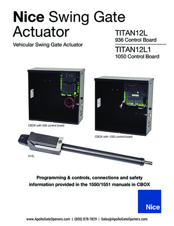
7 - PARTS IDENTIFICATION416 Actuator with 8’ harnessControl Box #11111BPivot Arm #1116(2 with 1600)8416X - Slave actuator with 38’ harness(Supplied with 1600)Gate Attach Bracket#10025215(2 with 1600)Bolt Kit(2 with 1600)
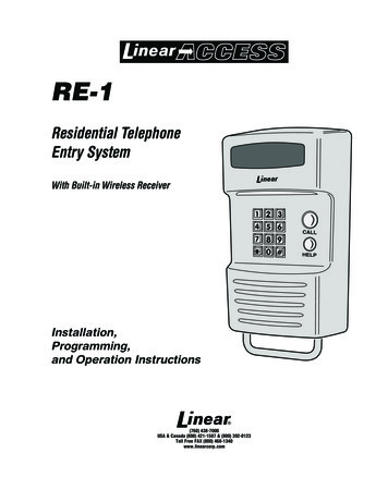
8 - PULL TO OPEN INSTALLATIONIMPORTANT - Never weld parts to the gate or posts when the operator circuit board is powered. Doing so may damagethe board beyond repair.8.1 - PIVOT ARM INSTALLATION - Location of Pivot PointThe following instructions provide up to 105 of swing.Measurements are taken from the center of pivot of the gate hinge.The pivot arm needs to be securely mounted to the hinge post or equivalent mounting surface. It is recommended to weldthe pivot arm to a metal post. In order to achieve the correct articulation, geometry and rate of speed of the gate it is criticalthat the measurements below are followed. The pivot arm may need to be cut to achieve the correct placement of theactuator mounting hole. Measurements are taken from the center of pivot of the gate hinge.LEFT HAND SWINGRIGHT HAND SWINGGATE CLOSEDDIRECTION OF OPENINGTOP VIEWNOTE: If you have columns built around your gate hinge post, check these measurements for proper clearancebefore proceeding with this pull to open installation.8.2 - Vertical position of pivot armCenter line ofattachment pointfor gate bracketThe top edge of the Pivot Arm will be located 1/2”below the center line for the gate bracket. The PivotArm must be level when secured.Hinge PostSIDE VIEW9
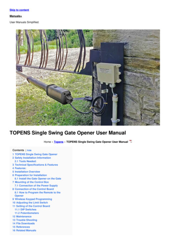
9 - PUSH TO OPEN INSTALLATION9.1 - PIVOT ARM INSTALLATION - Location of Pivot PointMeasurements are taken from the center of pivot of the gate hinge.The pivot arm needs to be securely mounted to the hinge post or equivalent mounting surface. It is recommendedto weld the pivot arm to a metal post. In order to achieve the correct articulation, geometry and rate of speed of thegate it is critical that the measurements below are followed. The pivot arm may need to be cut to achieve the correctplacement of the actuator mounting hole. Measurements are taken from the center of pivot of the gate hinge.LEFT HAND SWINGHINGE POSTRIGHT HAND SWINGHINGE POSTDIRECTION OF OPENINGGATES CLOSED6”6”11”TOP VIEW11”9.2 Vertical position of pivot armThe top edge of the Pivot Arm will be located1/2” below the center line for the gate bracket.The Pivot Arm must be level when secured.Center line of attachment pointfor gate bracketHinge Post9.3 - Wiring actuator(s) for push to openORIGINAL PIN WIRING1 ORANGE - Open Limit Input2 WHITE - Close Limit Input3 BLACK - Motor 4 RED - Motor 5 GREEN - Limit Switch Common6 Not used7 BLACK - Ground - Battery Negative8 RED - Battery Positive ( 12 VDC)10Strip back 6” of black sleeve from connector end of the actuator cable.Either cut and reverse the white and orange limit wires and the red andblack motor wires of the connector shown below or disconnect andmove the pins with the appropriate tool.NOTE: Do not reverse battery wires78563412PUSH TO OPEN PIN WIRING1 WHITE - Close Limit Input2 ORANGE - Open Limit Input3 RED - Motor 4 BLACK - Motor 5 GREEN - Limit Switch Common6 Not used7 BLACK - Ground - Battery Negative8 RED - Battery Positive ( 12 VDC)
10 - ACTUATOR MOUNTINGMount the actuator to the pivot arm as shown.Please notice the washer goes above the actuatorflange.The lock nut should be tight to prevent movement orshifting when the actuator is running. This will alsoprevent excessive “bounce” or “wobble” when the gatestops moving.11 - CONTROL BOX MOUNTINGMount the control box within 4 feet of the pivot arm. Use mountinghardware capable of supporting the weight of the control box with thebattery installed.Do not mount the control box where
This automatic gate opener is designed for vehicular traffic only. It is powerful and can cause serious bodily injury or death. Accordingly, direct all pedestrian traffic to a separate walk-through gate. The Apollo Model 1500/1600 Swing Gate Operator is designed to handle swing gates up to 16 feet in length and 600