Transcription
Manuals User Manuals Simplified.LIPPERT Hydraulic Leveling with LCD Touchpad Owner’sManualNovember 1, 2021November 13, 2021Home » LIPPERT » LIPPERT Hydraulic Leveling with LCD Touchpad Owner’s ManualLIPPERT Hydraulic Leveling with LCD Touchpad Owner’s Manual
Contents [ hide1 Introduction1.1 Component Description2 Safety3 Operation3.1 Selecting A Site3.2 Automatic Leveling Descriptive Logic3.3 Automatic Leveling Procedure3.4 Manual Leveling Procedure3.5 Automatic Jack Retract Procedures3.6 Manual Jack Retract Procedures4 Troubleshooting4.1 Manual Override of The Power System andJacks4.2 Automatic Safety Shutoff4.3 Drive-Away Protection System4.4 Jacks Up Verification4.5 Error Mode4.6 Excess Slope4.7 User Alarm Mode4.8 Miscellaneous4.9 Low Voltage Signal4.10 Troubleshooting Table4.11 Zero Point Calibration5 Maintenance5.1 Fluid Recommendation5.2 Purging the Hydraulic System5.3 Preventative Maintenance6 Wiring Diagram (Non-Water Resistant)7 Wiring Diagram (Water Resistant)8 Hydraulic Plumbing Diagram (Aluminum Jacks)9 Hydraulic Plumbing Diagram (Steel Jacks)10 Documents / Resources10.1 References10.2 Related Manuals / ResourcesIntroductionThe four-point three-valve hydraulic leveling system is a hydraulic system which includes four points of contact utilizing eithersteel or aluminum jacks, and a three-valve manifold system. A 12V DC electric motor drives a hydraulic pump that moves fluidthrough a system of hoses, fittings and jacks, to level and stabilize the coach. Mechanical portions of the hydraulic levelingsystem are replaceable. Contact Lippert Components, Inc. to obtain replacement parts.The hydraulic leveling system is primed and tested at the factory. However, the system is shipped dry to avoid hazardous materialrestrictions.Note: This manual replaces the following previously released LCI manuals: Class C Hydraulic Leveling Owner’s Manual (CCD0001514) dated 07.19.18 and Class C Hydraulic Leveling (Weld-on) Owner’s Manual (CCD-0001487) dated 06.20.18. These twomanuals were consolidated into this manual.For information on the assembly or individual components of this product, please lcd-br4-point3-valveComponent Description1. JacksA. 5K steel or 8K aluminumB. Rated at a lifting capacity for the coachC. Standard 9-inch diameter (63.5 square inch) footpad on a ball swivel for maximum surface contact on all surfacesD. Operational powered from a 12V DC motor/pump assembly2. Motor/Pump AssemblyA. 12V DC motorB. Hydraulic fluid reservoir tankC. Control valve manifold
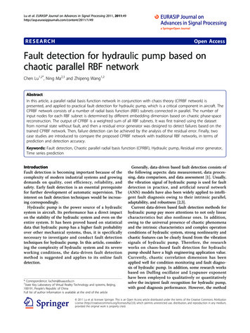
D. Solenoid valve3. System ControlsA. Controlled electronically from the touchpadB. Touchpad can be operated in manual mode or fully automatic mode4. Fittings and HosesA. Fittings – High pressure O-Ring Face or J.I.C. – Size 4B. Hose – 1/4″ I.D., 3000 psi – W.P. RatedSafetyPlease read and study the operating manual before operating the leveling system.WARNINGThe “WARNING” symbol above is a sign that a procedure has a safety risk involved and may cause death or serious personalinjury if not performed safely and within the parameters set forth in this manualWARNINGDuring servicing make sure that the coach is supported according to the manufacturer’s recommendation. Lift the coach by theframe and never the axle or suspension. Do not go under the coach unless it is properly supported. Unsupported coaches can fallcausing death or personal injury or product or property damage.WARNINGFailure to act in accordance with the following may result in serious personal injury or death.CAUTIONThe “CAUTION” symbol above is a sign that a safety risk is involved and may cause personal injury and/or product or propertydamage if not safely adhered to and within the parameters set forth in this manual.CAUTIONMoving parts can pinch, crush, or cut. Keep clear and use cautionThe use of the Lippert Components, Inc. Hydraulic Leveling System to support the coach for any reason other than which it isintended, is prohibited by the Lippert Limited Warranty. The Hydraulic Leveling System is designed as a leveling system only andshould not be used for any reason to provide service under the coach, e.g. changing tires or servicing the leveling system.Lippert Components, Inc. recommends that a trained professional be employed to change the tires on the coach. Any attempts tochange tires or perform other service while the coach is supported by the hydraulic leveling system could result in damage to thecoach and/or cause serious injury or death.OperationNote: It is recommended that the engine idle to maintain the minimum required voltage of 12.75V DC. The leveling systemshould only be operated under the following conditions:1.2.3.4.The coach is parked on a reasonably level surface.The coach parking brake is engaged.The coach transmission should be in the park position.Make sure all people, pets and property are clear of the coach while the hydraulic leveling system is in operation.CAUTIONAfter starting the automatic leveling cycle it is very important to not move around in the coach until the coach is level and thegreen LED light illuminates in the center of the touchpad. Failure to remain still during the leveling cycle could have an effect onthe performance of the leveling system.Fig. 1
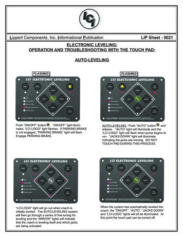
Note: Coaches manufactured before January 2018 will utilize the black touchpad.CalloutDescriptionAUp Arrow (UP) – Scrolls up through the menu on LCD.BDown Arrow (DOWN) – Scrolls down through the menu on LCD.CENTER – Activates modes and procedures indicated on LCD.DRETRACT- Places leveling system into retract mode. — Manual mode ONLY Press and hold for severalseconds to activate Auto Retract Function.ELCD Display – Displays procedures and results.FAUTO LEVEL – Places leveling system into auto level mode.GFRONT Jack Button – Activates both front jacks in manual mode.HLEFT Jack Button – Activates left rear jack in manual mode.IRIGHT Jack Button – Activates right rear jack in manual mode.JREAR Jack Button – Activates both rear jacks in manual mode.KPower Button – Turns leveling system on and off.Selecting A SiteWhen the coach is parked on an excessive slope, the leveling requirements may exceed the jack lift stroke capability. If the coachis parked on an excessive slope, the coach should be moved to a more level surface before the leveling system is deployed.“EXCESS ANGLE” will appear on the LCD screen if the coach is 3.5 degrees out of level front-to-rear or side-to-side.WarningWhile utilizing leveling blocks and jack pads, all coach wheels MUST not leave the ground during leveling. Lifting all the wheelsoff the ground creates a condition where severe property damage, serious personal injury or possible death may occur.Automatic Leveling Descriptive LogicGrounding: The following steps describe the process of how the auto-leveling sequence extends the jacks to the ground:1. Depending on which end of the coach is lowest to the ground, the level sensor in the controller will activate the jacks — thelowest end first, either front or rear.A. If the rear of the coach is the lowest end, ground the lowest rear jack first.B. If the front end is the lowest end, ground the front jack closest to the power unit.2. Ground the lowest remaining front or rear end jack.3. Lift lowest end jacks together until level.4. The leveling system will then ground remaining end jacks.A. If the rear of the coach is the remaining end, ground lowest jack first.B. If the front of the coach is the remaining end, ground the front jack closest to the power unit.5. Ground the remaining front or rear remaining end jack.
6. Lift remaining end jacks together until level.Leveling: The following steps describe the process of how the auto-leveling sequence levels the coach once the jacks havebeen grounded. This process may repeat several times until level.1. Front-to-rear2. Side-to-side3. Individually4. Minor adjustments to confirm groundingAutomatic Leveling ProcedureNote: Refer to Component Description listing in the System Information section for questions regarding component locations andfunctions of the hydraulic leveling system.Note: The engine MUST be running and the parking brake MUST be engaged for the hydraulic leveling system to operate.Note: Pressing any button during an automatic sequence will stop the sequence and a “Function Aborted” error code will occur.Press ENTER to clear the code and then continue the operation or start a new function.1. Press Power Button to turn system on (Fig. 1K). The green light will illuminate.2. Press Auto Level (Fig. 1F). LCD Screen will display “Remain Still.”3. The coach will level automatically and indicate “Auto Level – Success” in the LCD display (Fig. 1E).Note: Display will then read “Level – Jacks: Down.” Do not press any buttons until this message appears or a “FunctionAborted” error will be displayed.4. Visually inspect all jacks to make sure all footpads are touching the ground. If either of the rear jack footpads is not touchingthe ground, press LEFT or RIGHT (Fig. 1H or Fig. 1I) to lower the non-compliant jack to the ground.Manual Leveling ProcedureNote: The coach should be leveled front-to-rear first and then leveled side-to side.Note: The engine MUST be running and the parking brake MUST be engaged for the hydraulic leveling system to operate.Note: Performing manual leveling on a coach requires a minimum of 9.5V DC.1. Press Power Button (Fig. 1K) to turn system on.2. Press the Up Arrow (Up) or the Down Arrow (Down) (Fig. 1A or Fig. 1B) to scroll through control features until “ManualMode” is displayed.3. Press Enter (Fig. 1C).4. Press Front (Fig. 1G) to extend front jacks to the ground.5. Press Rear (Fig. 1J) to extend rear jacks to ground, then level the coach front to-back.6. Press appropriate Left or Right to level the coach side-to-side.Note: Red lights next to the buttons on touchpad will indicate which side(s) of the coach needs to be raised to achieve levelcondition.Note: The front jacks will work in pairs, i.e., FRONT operates both front jacks.Note: The right and left rear jacks are used to level the coach side-to-side. Pressing LEFT (Fig. 1H) will extend the left rearjack. Pressing RIGHT (Fig. 1I) on the touchpad will extend the right rear jack.7. Repeat steps 4-6 as needed.8. Turn off power to leveling system by pressing the Power Button (Fig. 1K).9. Visually inspect all jacks to make sure all footpads are touching the ground. If either of the rear jack footpads is not touchingthe ground, press LEFT or RIGHT (Fig. 1H or Fig. 1I) to lower the noncompliant jack to the ground.Automatic Jack Retract ProceduresNote: Pressing any button during an automatic sequence will stop the sequence and a “Function Aborted” error code will occur.Press ENTER to clear the code and then continue the operation or start a new function.1. Energize the system by pressing the Power Button (Fig. 1K) on the touchpad. The LCD screen will display “READY Jacks:Down.”2. Press Up Arrow (UP) or Down Arrow (DOWN) (Fig. 1A or Fig. 1B) to display “Auto Retract All” on the screen.3. Press ENTER (Fig. 1C) to begin.Note: “AUTO RETRACT” can also be commenced by pressing and holding RETRACT (Fig. 1D) for one second.4. The jacks will retract and shut off automatically.A. The display will read “READY – Jacks: Up.”B. Press the Power Button (Fig. 1K) on the touchpad to de-energize the system.C. Perform a brief visual inspection around the coach to verify the jacks are fully retracted.Manual Jack Retract Procedures
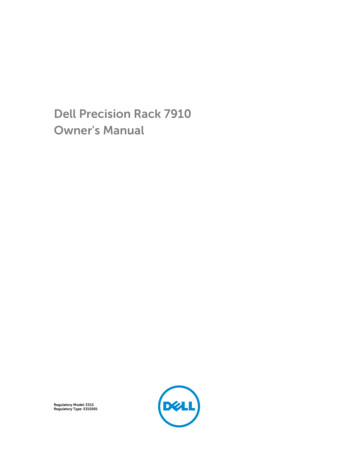
To retract in MANUAL mode, do as follows:WarningAll coach wheels MUST NOT leave the ground during leveling. Lifting all the wheels off of the ground creates a condition wheresevere property damage, serious personal injury or possible death may occur.1.2.3.4.Press RETRACT (Fig. 1D) until green indicator light comes on.Pressing FRONT or REAR (Fig. 1G or Fig. 1J) will operate the respective jacks in pairs.Pressing RIGHT (Fig. 1I) will operate the right rear jack.Pressing LEFT (Fig. 1H) will operate the left rear jack.TroubleshootingCautionMake sure all jacks are fully retracted before travel.Manual Override of The Power System and JacksIn the event that the jacks do not retract, the cartridge valves can be manually overridden.Note: Cartridge valves should be opened prior to operating with any auxiliary power device.The hydraulic leveling system can be operated in conjunction with auxiliary power devices, like cordless or power drills. In theevent of electrical or system failure, the manual method of retracting the jacks can be used. A standard hand-held drill is all that isrequired.CautionDo not over-tighten override set screws as this can damage the valves.1.2.3.4.5.6.7.Use a 5/32″ hex key to turn the manual override clockwise (Fig. 2) on each of the three cartridge valves to open the valves.Disconnect or shield power cables on the motor.Remove plastic cap (Fig. 3A) from motor coupler.Unplug the wire harness from the directional valve. See Wiring Diagram.Using a 1/2” socket and auxiliary drive device, e.g. cordless or power drill, insert 1/2” socket onto coupler (Fig. 4A).Run drill in reverse, or counterclockwise direction, to simultaneously retract all jacks.After all jacks have been retracted, turn all manual overrides on the cartridge valve counterclockwise (Fig. 5).8. Reinsert previously removed protective plastic motor coupler cap.
9. Re-attach previously unplugged wire harness to directional valve.Automatic Safety ShutoffThe touchpad will automatically shutoff after four minutes, if left inactive. To reset the system, turn the coach’s ignition off, thenback on. Press the touchpad’s Power Button (Fig. 1K) again.Drive-Away Protection SystemIf the ignition is in the “RUN” position, jacks are extended and the operator releases the parking brake, all indicator lights will flashand the alarm beeper will activate. The leveling system will automatically fully retract the jacks to clear the alarm or, if theoperator resets the parking brake, the alarm will shut off.Jacks Up VerificationIf the coach’s ignition is in the “RUN” position, the parking brake is released and the vehicle is in motion, the leveling system mayactivate the power unit to ensure retract pressure is high enough to keep jacks fully retracted. The LCD screen will say “JACKSUP VERIFICATION” until the retract pressure returns to normal level. The touchpad will shut off. No beeping will occur and the“JACKS DOWN” dash light will not illuminate.Error Mode1. If an error occurs before or during operation, the error will be displayed in the touchpad’s LCD screen (Fig. 1E) and analarm will sound. To reset common ERROR displays, press ENTER (Fig. 1C).Note: To reset “Return for Service” errors, press ENTER (Fig. 1C) and RETRACT (Fig. 1D) simultaneously. Refer to ErrorCode Chart for additional error codes.2. All normal functions will be disabled while the system is in Error Mode
Error Code ChartLCD DisplayExcess AngleWhat is Happening?Coach not parked on level ground. Zeropoint incorrectly calibrated.What Should Be Done?Move coach to level ground prior to startingauto level sequence.Recalibrate Zero Point.Excessive AngleOccurs only in manual mode when theangle of the coach is too severe.Use the manual functions to return coach toa more level condition.Out of StrokeJack has insufficient length to completethe leveling procedure.Check the disposition of the jack.Low VoltageBattery voltage dropped below 9.5V DCduring operation.Turn engine on, check battery voltageunder load.Function AbortedA button was pressed on touchpad during Hit enter to acknowledge. RestartAuto Level operation.procedure.Unable to Finish LevelingExcessive movement inside coach during Discontinue movement inside coach duringauto level sequence.auto level sequence.Engage Park BrakeParking brake not set prior to starting auto Set parking brake prior to starting auto levellevel sequence.sequence.Comm Error Check WiringNOTE: Screen will not back light.Retract TimeoutReturn Levelers for ServiceWiring connections loose or faulty between Check connections, replace communicationtouchpad and controller.harness if necessary.Pressure switch did not sense retractpressure and pump timed out.Leaking hose or fitting.Return levelers for service.Check for leaks, repair if necessary. Pressenter and retract to clear error.Excess Slope1. The control will not operate at extreme slopes, i.e. 3.5 degrees front and rear and 3.5 degrees side-to-side.2. If the coach’s display indicates “Excess Angle” or “Out of Stroke “ during an auto-level cycle, move the coach to a level spot.User Alarm ModeIf the alarm system detects that the park brake has been disengaged while at least one jack is not fully retracted, the touchpad willbuzz and the LED will signal a park break error to the user. The system will then perform an automatic retract sequence. No other
features are available in this mode.Miscellaneous1. A “Re-Level” feature is programmed into the controller. If the jacks are extended and the user presses AUTO LEVEL(Fig.1F), the system will re-level from that point. The system will not retract before performing the re-level.2. System will refuse any operation when a low voltage condition is present.Low Voltage Signal1. The vehicle requires 12.75V DC to operate in the AUTO mode. If the voltage is too low, the screen will display “LowVoltage.”2. Minimum Voltage – If voltage drops below 9.5V DC during AUTO or MANUAL operation, “Low Voltage” will appear in thescreen and the system will cease operating.Note: Coach will operate in manual mode between 9.5V DC and 12.75V DC.Troubleshooting TableWhat Is Happening?Why?What Should Be Done?Coach ignition is not in RUN position. Turn ignition to RUN position.System will not turn on and theon/off indicator light does notilluminate.Touchpad turns on, but turns offwhen jack directional buttons arepressed or touchpad displays“low voltage.”Touchpad has been on, but inactivefor more than four minutes and has Turn ignition OFF and then back ON.timed out.Tripped or blown circuit protection.Reset or replace circuit protection.Low voltage on battery.Start coach to charge battery.Touchpad turns on, coach will notauto-level, “Jacks Down”Low fluid level.displayed, jacks are retracted.Jacks will not extend to groundwhile pump is running.Check fluid level in reservoir. Fluid is low,with jacks retracted, add fluid to 1/2″ from top ofreservoir. If “Jacks Down” lightremains on, call Lippert Customer Service.Little or no fluid in reservoir.Add fluid as recommended.Cartridge valve is inoperative.Clean, repair, or replace cartridge valve.
Electronic signal is lost betweencontroller and coil.Trace wires for voltage drop or loss, or no valve signals.Repair or replace necessary wires or replace controlpad.Hose damaged or unconnected.Replace with new hose or reconnect hose.Cartridge valve is inoperative.Replace inoperative cartridge valve.Electronic signal is lost betweencontroller and coil.Attempt to retract jacks in MANUAL mode. Ifsuccessful, replace touchpad; if not, test for voltagedrop between touchpad and coil, repair bad wiring orreplace defective controller or cartridge valve.Low fluid level.Add fluid as recommended.Retract pressure switch inoperable.Check connection or replace pressure switch.Low fluid level.Add fluid as recommended.Retract pressure switch inoperable.Check connection or replace pressure switch.Any one or two jacks will notretract.“READY – Jacks: Up” does notdisplay when all jacks areretracted.Alarm sounds and “Jacks Down”light starts flashing whiletraveling; jacks are fully retracted.
Possible fluid leak.Check for fluid leaks and repair or replace componentsas necessary.Coach bleeds down after jacks areextended. Jack bleeds down afterbeing retracted.Cartridge valve manual override Close override, see Manual Override of The Poweropen.System and Jacks.Loose ground wire at power unit. Check for loose wires.Touchpad powers up; screen displays“low voltage.”Engine not running.Start coach engine.Tripped or blown circuitprotection.Reset or replace circuit protection.Ignition not ON.Turn ignition ON.Error code “Unable to finishleveling.”Move coach to a level site.No power to touchpad.Auto level function does not finish.Zero Point CalibrationBefore auto-leveling features are available, the Zero Point MUST be set. This is the point the system will return to when an autoleveling cycle is initiated. The Zero Point calibration has been set by the RV manufacturer and verified by the RV dealer. If a newZero Point is desired, follow the instructions in this section.To set the Zero Point, first run a manual leveling sequence to get the coach to the desired level point. Then activate the ZeroPoint configuration mode. This mode is enabled by performing the following sequence:1. Run a manual leveling sequence to set the trailer to the desired level point.2. Activate the Zero Point configuration mode as follows:A. Turn off touchpad.B. Press FRONT button (Fig. 1G) 10 times.C. Press REAR button (Fig. 1J) 10 times.Note: An alarm will sound and the display will read ZERO POINT CALIBRATION; ENTER to set, Power to Exit (Fig.6).D. Press ENTER (Fig. 1C) to set the Zero Point.3. Screen will then display PLEASE WAIT.4. An alarm will sound and the screen will display “Zero point set successfully” (Fig. 7).5. The touchpad will then turn off.MaintenanceFluid RecommendationAutomatic transmission fluid (ATF) with Dexron III or Mercon V or a blend of both is recommended by Lippert Components, Inc.For a list of approved fluid specifications, see TI-188. To obtain this Technical Information sheet on-line, go to
http://www.lci1.com/support-lci4a3lcd. Then click on the Technical Information Sheets tab. Look for TI-188: Hydraulic OperationFluid Recommendation within the listing.Note: In colder temperatures (less than 10 F) the jacks may extend and retract slowly due to the fluid’s molecular nature. Forcold weather operation, fluid specially formulated for low temperatures may be desirable.Purging the Hydraulic SystemWarningThe coach should be supported at both front and rear axles with jack stands before working underneath. Failure to do so mayresult in death, serious personal injury or severe product or property damage.Note: Make sure jacks are fully retracted prior to filling reservoir to prevent over-filling.1. Zip-tie any loose wiring or hydraulic lines.Note: The basic purge procedure to bleed the LCI Hydraulic Systems can be performed without the use of any tools. Thehydraulic system will purge the air from the hydraulic lines and cylinders by simply running the pump.Note: It is recommended to perform a minimum of three complete cycles (steps 2-7) to ensure both proper function andadequate fluid level of the system.2. Start with all hydraulic components in the fully retracted position, meaning all jacks and slide-outs are brought back insidethe coach as if the coach were ready for travel.3. Find the hydraulic pump location and note the amount of fluid currently in the reservoir. The fluid level should be about 1/4”from the top of the reservoir and no more than 1/2” from the top.Note: When checking the fluid level after ensuring all hydraulic components are retracted, note if there are any bubbles,froth or foam on top of the fluid. This is an indication that air has been pushed back to the reservoir when the hydrauliccomponents were retracted in the last cycle. Wait 15-20 minutes for the foam to dissipate before beginning the purgeprocess.4. If there is no froth or foam in the reservoir and the fluid is not within 1/2” of the top, fill the reservoir to within the leveldescribed in step 3.5. With the fluid level full and no foam in the reservoir, begin cycling the hydraulic system.6. Extend jacks fully, taking the coach off the tires. If the coach has hydraulic slide-outs, extend all slideouts. Once all jacksand slide-outs are extended, immediately retract all slide-outs and then jacks.7. Check the reservoir foam. If foam is present, see NOTE following step 3 and then repeat steps 4-6. Repeat these steps untilno foam is present in the reservoir. If no foam is present, the system is purged of air.Preventative Maintenance1. Check hydraulic fluid in reservoir every 12 months. If fluid is a clear, red color, do not change. If fluid is milky, pink andmurky, and not clear red in color, drain reservoir and add new fluid. Hydraulic fluid in reservoir should be changed aminimum of every five years.Note: Check the hydraulic fluid only when all the jacks are fully retracted.Note: When checking the hydraulic fluid level, fill reservoir to within ¼” to ½” of fill spout.2. Inspect and clean all power unit electrical connections every 12 months. If corrosion is evident, spray connections withelectrical contact cleaner.3. Remove dirt and road debris from jacks as needed.4. If jacks are extended for long periods of time, it is recommended to spray exposed jack rods with a dry silicone lubricantevery three months for protection. If the coach is located in a salty environment, it is recommended to spray the rods everyfour to six weeks.Wiring Diagram (Non-Water Resistant)
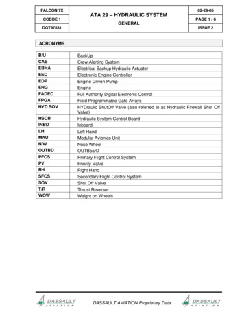
Wiring Diagram (Water Resistant)Hydraulic Plumbing Diagram (Aluminum Jacks)
Hydraulic Plumbing Diagram (Steel Jacks)NotesThe contents of this manual are proprietary and copyright protected by Lippert Components, Inc. (“LCI”). LCI prohibits the
copying or dissemination of portions of this manual unless prior written consent from an authorized LCI representative has beenprovided. Any unauthorized use shall void any applicable warranty. The information contained in this manual is subject to changewithout notice and at the sole discretion of LCI. Revised editions are available for free download from lci1.com.Please recycle all obsolete materials.For all concerns or questions, please contact Lippert Components, Inc.Ph: (574) 537-8900 Web: lci1.com Email: customerservice@lci1.comDocuments / ResourcesLIPPERT Hydraulic Leveling with LCD Touchpad [pdf] Owner's ManualLIPPERT, Hydraulic, Leveling, LCD, Touchpad, 4 Point, 3 Valve, MotorizedLIPPERT Hydraulic Leveling [pdf] Owner's ManualLIPPERT, Hydraulic, Leveling, 4 POINT, 3 VALVE, SPRINTERReferencesHome LippertHydraulic Leveling LCD (4 Point/3 Valve) Lippert Customer SupportLippert Customer Care Center Lippert Customer SupportLippert Customer Care Center Lippert Customer SupportHydraulic Leveling LCD (4 Point/3 Valve) Lippert Customer SupportLippert Customer Care Center Lippert Customer SupportHome LippertRelated Manuals / Resources336 Hydraulic Excavator Specifications Manual336 Hydraulic Excavator Specifications Manual - Optimized PDF 336 HydraulicExcavator Specifications Manual - Original Acer LCD Monitor User ManualAcer LCD Monitor User Manual Acer-LCD-Monitor-User-Manual-OriginalAcer LCD Monitor User ManualAcer LCD Monitor User Manual - Optimized PDF Acer LCD Monitor User Manual Original Benq LCD Monitor User ManualBenq LCD Monitor User Manual What is in the box? Installation Product Specification Remote Control
Manuals ,homeprivacy
A. Controlled electronically from the touchpad B. Touchpad can be operated in manual mode or fully automatic mode 4. Fittings and Hoses A. Fittings - High pressure O-Ring Face or J.I.C. - Size 4 B. Hose - 1/4″ I.D., 3000 psi - W.P. Rated Safety Please read and study the operating manual before operating the leveling system. WARNING