Transcription
2.3 - 7.2kVMOTORTRONICS Solid State AC Motor ControlMedium VoltageSolid State OEM Soft StarterINSTALLATION & OPERATIONMANUAL3052301MN00011601MN-1-
2.3 - 7.2kV
Chapter 1: Introduction .12.3 - 7.2kVMedium Voltage SolidState Soft Starters2.3 - 7.2KVInstallation &Operation nsDesign FeaturesTheory of OperationGeneral ProtectionThermal Overload ProtectionFiring CircuitElectronicsChapter 2: Connections . 92.12.22.3WarningsControl ConnectionsReference Section with RTD, Power, Communications and CPU board drawingsChapter 3: Start-Up . 173.13.23.33.43.5IntroductionAcceleration AdjustmentsDeceleration AdjustmentsSequence of Normal OperationEmergency Bypass OperationChapter 4: User Interface and Menu Navigation . 214.14.2Keypad/Operator InterfaceMenu NavigationChapter 5: Setpoint Programming . 245 .15.2Setpoints Page ListSetpoint MenuSP.1 Basic Configuration . 34SP.2 Starter Configuration . 35SP.3 Phase & Ground Settings . 38SP.4 Relay Assignment . 41SP.5 Relay Configuration . 43SP.6 I/O Configuration . 44SP.7 Custom Acceleration Curve . 47SP.8 Overload Curve Configuration . 50SP.9 RTD Option Configuration . 51SP.10 Set Password . 53SP.11 Communications . 54SP.12 System Setpoints . 55SP.13 Calibration & Service . 57Chapter 6: Metering Pages . 586 .1Metering Page List & MenuChapter 7: Maintenance and Troubleshooting . 687.17.27.37.47.57.67.77.8Failure AnalysisTypical Block DiagramOverload Curve DefinitionTCB DiagramTypical Wiring DiagramSpare Parts ListInstructions for Stack ReplacementInstructions for Low Voltage Test
2.3 - 7.2kVReference chartTable orDrawingSectionTable ent Trip Delay Graph391.2Specifications1.3Unit PIV Ratings35.2Setpoint Page 4 Displays - RelayAssignment411.8Keypad Operator Interface85.2Setpoint Page 5 Displays - RelayConfiguration432.2TCB Diagram105.2Setpoint Page 6 Displays - User I/OConfiguration44 - 462.2TB1105.2Setpoint Page 7 Displays - CustomAcceleration Curve47 - 492.2TB2105.2Setpoint Page 8 Displays - OverloadCurve Configuration502.2TB3115.2Setpoint Page 9 Displays - RTD OptionConfiguration512.2TB4115.2Setpoint Page 10 Displays - SetPassword532.2Jumper Selections125.2Setpoint Page 11 Displays Communications542.2Switch Positions125.2Setpoint Page 12 Displays - SystemSetpoints552.3Optional RTD Board135.2Setpoint Page 13 Displays - Calibration& Service572.3Communications Board146.1Metering Page List2.3Communications Board Connections:RS485 and RS422146.2Metering Menu602.3Power Board156.2Metering Page 1 Displays - MeteringData612.3Power Board Connections156.2Metering Page 2 Displays - Metering622.3CPU Board Connections166.2Metering Page 3 Displays - RTD Values633.2Acceleration Adjustments176.2Metering Page 4 Displays - Status643.3Coasting Stop186.23.33.44.14.14.24.25.15.2Accel and Decel ModesSequence of OperationsKeypad Operator InterfaceProgramming the Operator InterfaceMenu NavigationChanging Setpoints ExampleSetpoints Page ListSetpoint Menu18192121222324 - 32335.25.25.25.25.2Setpoint Page 1 Displays - BasicConfigurationOverload Class Trip CurvesSetpoint Page 2 Displays - StarterConfigurationJog/Voltage RampSetpoint Page 3 Displays - Phase &Ground Settings58 - 596.26.27.17.17.27.37.47.5Metering Page 5 Displays - EventRecorderMetering Page 6 Displays - Last TripMetering Page 7 Displays - StatisticsTroubleshooting ChartsSCR Testing ProcedureTypical Block DiagramOverload Curve DefinitionTCB DiagramTypical Wiring Diagram666768 - 707071727374347.6Spare Parts List Charts76 - 77347.6PCB Mounting Order77357.7Stack replacement and PCB mounting78367.7Connections for Low Voltage8238 - 397.8Waveform Diagram8465
2.3 - 7.2kVChapter 1 - IntroductionThis chapter is an introduction to the reduced voltage solid state starter formedium voltage AC motors. It describes the basic configuration, operation andunit features. It is highly recommended that new users read this sectionthoroughly to gain a basic understanding of the starter system before attemptingto start up a unit.1.1 OverviewThe standard soft starter panel is an SCR-based motor controller designed forthe starting, protection and control of AC medium voltage motors. It containsthe SCR stack assemblies, fiber optic connections and low voltage controlcircuitry ready to be interfaced with an enclosure and the necessary equipment to create a complete Class E2 medium voltage motor soft starter.1.2 SpecificationsUnit Overload Capacity(Percent of motor FLA)125% - Continuous500% - 60 seconds600% - 30 seconds1 Cycle: up to 14 x FLA (internally protected by the programmable short circuit)Frequency50 or 60Hz, 2Hz hardware selectablePower Circuit6 SCRs, 12 SCRs or 18 SCRs (model dependent)SCR Peak InverseVoltage Ratings6500V - 21000V (model dependent see Table 1)Phase InsensitivityUser selectable phase sequence detectionTransient Voltage ProtectionRC snubber dv/dt networks (one per SCR module)Ambient Condition DesignEnclosed units: 0 to 40 C (32 to 104 F) (optional - 20 to 50 C with heaters)5 - 95% relative humidity0 - 3300 ft. (1000m) above sea level without derating(Ratings for ambient conditions external to unit)Control2 or 3 wire 120VAC (customer supplied)Multiple: Form C (contacts), rated 4 Amps, 250VAC max.Auxiliary Contacts8 Relays (4 programmable) - Form C contactFault Indicator: Form C contactBIL Rating2300V - 7200VApprovalsUL Recognized, Canadian UL Recognized60kV-1-
2.3 - 7.2kV1.2 Specifications (continued)Advanced Motor ProtectionTwo Stage ElectronicOverload CurvesStarting: Programmable for Class 5 through 30Run: Programmable for Class 5 through 30 when "At-Speed" is detected.Overload ResetManual (default) or automaticRetentive Thermal MemoryOverload circuit retains thermal condition of the motor regardless of controlpower status. Unit uses real time clock to adjust for off time.Dynamic Reset CapacityOverload will not reset until thermal capacity available in the motor is enough fora successful restart. Starter learns and retains this information by monitoringprevious successful starts.Phase Current ImbalanceProtectionImbalance Trip Level: 5 - 30% current difference between any two phasesImbalance Trip Delay: 1 - 20 secondsOver Current ProtectionTrip Level: 100 - 300% of motor FLATrip Delay: 1 - 20 secondsLoad Loss Trip ProtectionUnder Current Trip Level: 10 - 90 % of motor FLAUnder Current Trip Delay: 1 - 60 secondsCoast Down (Back Spin)Lockout TimerCoast Down Time Range: 1 - 60 minutesStarts-per-hour Lockout TimerRange: 1 - 6 successful starts per hourTime between starts: 1 - 60 minutes between start attemptsProgrammable OutputsType / RatingForm C (DPDT), Rated 4 amps 240 VAC max, (960 VA)Run IndicationProgrammableAt Speed IndicationProgrammableAcceleration AdjustmentsProgrammable Ramp Types: Voltage or Current Ramp (VR or CR)Starting Torque: 0 - 100% of line voltage (VR) or 0 - 600% of motor FLA (CR)Ramp Time: 1 to 120 secondsCurrent Limit: 200 - 600% (VR or CR)Dual Ramp Settings4 Options: VR1 VR2; VR1 CR2; CR1 CR2; CR1 VR2Dual Ramp Control: Ramp 1 DefaultRamp 2 selectable via dry contact inputDeceleration AdjustmentsBegin Decel Level: 0 - 100% of line voltageStop Level: 0 to 1% less than Begin Decel LevelDecel Time: 1 - 60 secondsJog SettingsVoltage Jog: 5 - 75%Kick Start SettingsKick Voltage: 10 - 100%Kick Time: 0.1 - 2 secondsFault DisplayShorted SCR, Phase Loss, Shunt Trip, Phase Imbalance Trip, Overload,Overtemp, Overcurrent, Short Circuit, Load Loss, Undervoltage or Any TripLockout DisplayCoast Down Time, Starts Per Hour, Time Between Starts, and Any LockoutEvent HistoryUp to 60 EventsData includes cause of event, time, date, voltage, power factor and current foreach phase and ground fault current at time of event-2-
2.3 - 7.2kV1.2 Specifications (continued)Metering FunctionsMotor LoadPercent of FLACurrent DataA, B, C Phase Current, Avg Current, Ground Fault (option)Thermal DataRemaining thermal register; thermal capacity to startStart DataRTD Data (Option)Avg Start Time, Avg Start Current, Measured Capacity to start, time since laststartTemperature readings from up to 12 RTDs (up to 6 stator RTDs)Voltage MeteringkW, kVAR, PF, kWHSerial CommunicationsProtocolModbus RTUSignalRS-485, RS-422 or RS232NetworkUp to 247 devices per modeFunctionalityFull operation, status view, and programming via communications portOperator InterfaceLCD ReadoutAlpha numeric LCD displayKeypad8 function keys with tactile feedbackStatus Indicators12 LEDs include Power, Run, Alarm, Trip, Aux RelaysRemote Mount CapabilityUp to 1000 circuit-feet from chassis (use twisted, shielded wire &power source)Clock and MemoryOperating MemorySRAM loaded from EEPROM at initializationFactory Default StorageFlash EPROM, field replaceableCustomer Settings and StatusNon-volatile EEPROM, no battery backup necessaryReal Time ClockLithium ion battery for clock memory only1.3 Design Features200 & 400 Ampere UnitsThe standard soft start panel has the following features: SCR Power Modules: For each phase, the SCRs arematched devices arranged in inverse parallel pairs and inseries strings as indicated in the chart to facilitate sufficientPeak Inverse Voltage ratings for the applicable supplyvoltage.RC Snubber Networks: provide Transient Voltage Protection for SCR Power Modules in each phase to avoid dv/dtdamage.Firing Circuit: The SCRs are gated (turned on) using aSustained Pulse Firing Circuit. This circuitry is amplified andisolated from the control voltage by means of fiber optics andring transformers.VoltageSeriesPairs2300 V3300 / 4160 V6000 - 7200 V023PIV Rating6500 V13000 V19500 V600 Ampere UnitsVoltageSeriesPairs2300 V3300 / 4160 V6000 - 7200 V2461.4 Theory of OperationThe power of the soft starter is in the CPU, a microprocessor based protection andcontrol system for the motor and starter assembly. The CPU uses Phase AngleFiring of the SCRs to apply a reduced voltage to the motor, and then slowly andgently increases torque through control of the voltage and current until the motoraccelerates to full speed. This starting method lowers the starting current of themotor, reducing electrical stresses on the power system and motor. It also reducespeak starting torque stresses on both the motor and load mechanical components,promoting longer service life and less downtime.-3-TotalNumberof SCRs61218TotalNumberof SCRs122436Unit PIV RatingsTable 1PIV Rating7000 V14000 V21000 V
2.3 - 7.2kVAcceleration: The soft starter comes standard with several methods ofaccelerating the motor so that it can be programmed to match almost anyindustrial AC motor application.The factory default setting applies a Voltage Ramp with Current Limit as thishas been proven the most reliable starting method for the vast majority ofapplications. Using this starting method, the Initial Torque setting applies justenough voltage to the motor to cause the motor shaft to begin turning. Thisvoltage is then gradually increased over time (as per the Ramp Time setting)until one of three things occur: the motor accelerates to full speed, the RampTime expires or a Current Limit setting is reached.If the motor accelerates to full speed before the ramp time setting has expired, an automatic Anti-Oscillation feature will override the remaining ramptime and full voltage will be applied. This will prevent any surging or pulsationin the motor torque, which might otherwise occur due to the load not beingfully coupled to the motor when operating at reduced voltage and torquelevels.If the motor has not reached full speed at the end of the ramp time setting, thecurrent limit setting will proportionally control the maximum output torque.Feedback sensors in the soft starter provide protection from a stall condition,an overload condition or excessive acceleration time.The Current Limit feature is provided to accommodate installations wherethere is limited power available (for example, on-site generator power or utilitylines with limited capacity). The torque is increased until the motor currentreaches the pre-set Current Limit point and it is then held at that level. CurrentLimit overrides the ramp time setting so if the motor has not accelerated to fullspeed under the Current Limit setting, the current remains limited for as longas it takes the motor to accelerate to full speed.When the motor reaches full speed and the current drops to running levels,the soft starter detects an At-Speed condition and closes the Bypass Contactor. The Bypass Contactor serves to shunt power around the SCR stackassemblies to prevent heat build-up in the starter enclosure due to the slightvoltage drop across the SCRs. At this point, the soft starter has the motoroperating at full voltage, just as any other starter would.Other starting methods available to the soft starter are:· Current Ramp: uses a closed current feedback PID loop to provide a lineartorque increase up to a Maximum Current level.· Constant Current: current is immediately increased to the Current Limit pointand held there until the motor reaches full speed.· Custom Curve: gives the user the ability to plot torque and time points on agraph. The soft starter will then accelerate the motor following these points.· Tachometer Input: uses 4-20mA monitoring signal from the motor or loadshaft.Deceleration: the soft starter provides the user with the option of having theload coast to a stop or of controlling the deceleration by slowly reducing thevoltage to the motor upon initiating a stop command. The Decel feature is theopposite of DC injection braking in that the motor will actually take longer tocome to a stop than if allowed to coast to a stop. The most common application for the Decel feature is pumping applications where a controlled stopprevents water hammer and mechanical damage to the system.-4-
2.3 - 7.2kV1.5 General ProtectionOperation of the soft starter can be divided into 4 modes: Ready, Start, Run andStop. The CPU provides motor and load protection in all four modes. Additionaldetails on each protection feature can be found in later chapters.Ready Mode: In this mode, control and line power are applied and the starteris ready for a start command. Protection during this mode includes themonitoring of current for leakage through multiple shorted SCRs or weldedcontacts on the Bypass Contactor. Other protection features in effect are:······Starter SCR TemperatureShorted SCRBlown Fuse IndicationPhase Reversal (if enabled)Line Frequency Trip WindowExternal Input FaultsNote: The “Programming Mode” can only be entered from the Ready Mode.During programming, all protection features and start command are disabled.Start Mode: These additional protection functions are enabled when the softstarter receives a valid Start command:··········Phase Reversal (if enabled)Start CurveAcceleration TimerPhase ImbalanceShort Circuit / Load Pre-checkGround Fault (Optional)External Input FaultsAccumulated Starting FLA UnitsOverload ProtectionThermal CapacityNote: Shorted SCR and Shunt Trip protection are not in effect once the softstarter goes into the Start Mode.Run Mode: The soft starter enters the Run Mode when it reaches full outputvoltage and the motor current drops below the FLA setting (motor nameplateFLA times the service factor) for a pre-determined period of time. During theRun Mode these additional protection features are enabled:·····Running Overload CurvePhase LossUnder Current / Load LossOver Current / Electronic Shear Pin (Jam protection)External Input FaultsStop Mode: Once a Stop command has been given, the unit protectionfeatures change depending on which Stop Mode is selected.· Decel Mode: retains all protection features of the Run Mode. At the end ofDecel, the motor will be stopped and the protection features change asindicated below.· Coast-To-Stop Mode: power is immediately removed from the motor and thesoft starter returns to the Ready Mode.· Coast-Down / Back Spin Timer· Starts-per-Hour· Time Between Starts· External Input Faults-5-
2.3 - 7.2kV1.6 Thermal Overload ProtectionThe soft starter plays an important role in the protection of your motor in that itmonitors the motor for excessive thermal conditions due to starting, running oreven ambient conditions. The soft starter has a Dynamic Thermal Register systemin the CPU that provides a mathematical representation of the thermal state of themotor. This thermal state information is kept in memory and is monitored forexcesses in both value and rate of change. Input is derived from currentimbalances and (optional) RTD measurements making it dynamic to all processesinvolving the motor. The soft starter monitors these conditions separately duringStart and Run modes to provide proper thermal overload protection at all times.Start Mode overload protection is selectable using one of three methods:· Basic Protection: I2t data is accumulated and plotted based on an OverloadCurve selected in programming. This is programmed per NEMA Class 5-30standard curves and is based on the Locked Rotor Current (from the motornameplate) as programmed into the soft starter.· Measured Start Capacity: the user enters a measured amount of thermalcapacity from a pre-selected successful start as a setpoint to the ThermalRegister for the soft starter to follow.· Learned Curve Protection: the user sets the soft starter to the “LEARN” modeand starts the motor under normal starting conditions. The CPU then samplesand records 100 data points during the start curve, analyzes them and createsa graphical representation in memory. The soft starter is then switched to CurveFollow protection mode and monitors motor performance against this curve.This feature is especially useful in initial commissioning tests to record a baseline performance sample (in this case, it is not necessarily used for motorprotection).Run Mode overload protection is initiated when the soft starter determinesthat the motor is At-Speed. Overload Protection is initiated when the motorRMS current rises above a “pick-up point” (as determined by the motornameplate FLA and service factor). Run mode protection is provided by the CPUmonitoring the Dynamic Thermal Register. Data for the Dynamic ThermalRegister is accumulated from I2t calculations and motor cooling rates. A tripoccurs when the register reaches 100% as determined by the selectedOverload Protection Curve (NEMA Class 5-30 standard curves) and is basedon the programmed Locked Rotor Current indicated on the motor nameplate.The Dynamic Thermal Register is altered, or “biased”, by the following conditions:· Current Imbalance: will bias the register higher to account for additionalmotor heating during a current imbalance condition.· Normal Cooling: provided when the motor current drops below the pick-uppoint or the motor is off line. The cooling rate is lower for motors that are offline (such as after a trip) since cooling fans are also inoperative.· RTD Input: (requires the optional RTD monitor card): will bias the register ineither direction based on real-time input of the motor, bearing and evenambient temperature conditions.· Dynamic Reset is another feature that adds reliability and consistency tothe performance of the soft starter. If a motor overload condition occurs andthe soft starter trips, it cannot be reset until sufficient cool down time haselapsed. The cool down time is biased by RTD measurements when they areused. Otherwise, the cool down time is determined by the thermal state ofthe motor when the starter tripped.-6-
2.3 - 7.2kV· Retentive Memory provides continuous overload protection and real timereset even if power is lost. Upon restoration of power, the soft starter willread the Real Time Clock and adjust the thermal register to display whatwould be the true (or real) elapsed time.· Learned Reset Capacity is a feature that is unique to the soft starter. Bysampling the amount of thermal capacity used in the previous three starts,the soft starter will not allow a reset until a sufficient amount of thermalcapacity has been regained in the motor. This prevents nuisance tripping andinsures that unsuccessful start attempts where current is not present (whichwould otherwise use up the starts-per-hour capacity of the motor) are notcounted.1.7 Firing CircuitThe SCR gate firing circuit is critical to performance and stability of the system.The soft starter firing circuit includes several unique features which enhance theruggedness, noise immunity and flexibility for maximized performance. Thisperformance is attained without the need for reactors or field installed devices usedin other systems, regardless of conditions (line impedance, short circuit capacity orswitching transients). These features include:Auto Synchronizing of the gate timing pulses matches each phase firingangle to their respective phases. The soft starter actively tracks minor shiftsin the line frequency, avoiding nuisance tripping that may happen withconventional gate firing systems. This is especially useful on portable orbackup generator supplies, allowing the soft starter to be used confidently inapplications that have unstable power.Sustained Pulse firing keeps the firing signal active for 270 electrical degrees,ensuring that the DC gate pulse causes the SCR to fire even if line noise ispresent at a critical moment. This provides the soft starter with superiornoise immunity and protects against misfiring, enhancing the system reliability.Closed Loop Firing Control is a method of balancing the SCR firing patternbased on the desired output. The CPU uses feedback signals from both theoutput current and voltage providing smooth output and preventing imbalancesduring ramping which prevents unnecessary motor heating.Transformer Isolation of the firing signals prevents interference from linenoise and EMI/RFI signals that may be present. Specially designed 120V3 phase isolation transformers provide potential measurement, firing boardpower and gate power systems while being isolated from the line voltage.High isolation Ring Transformers are used to step this down to 28VAC for theSustained Pulse firing circuit, providing further isolation for the SCR gates.Fiber Optic Isolation is provided for all signal interfaces between theMedium Voltage and Low Voltage systems. Even the current signals fromCTs are converted to fiber optic signals for maximum isolation and safety.1.8 ElectronicsThe soft starter electronics systems are divided into two categories, Low Voltageand Medium Voltage, based solely on where they are located in the starterstructure.Low Voltage electronics include the Keypad Operator Interface, the CPU andMain Power PC boards are located in an isolated Low Voltage Compartmentof the enclosure.-7-
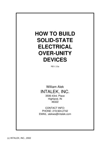
2.3 - 7.2kV· Keypad Operator Interface: a 2 line x 20 character LCD display withbacklighting for low ambient conditions. The display read-out is in truncatedEnglish and can show multiple data points in each screen. Also included are12 LED indicators, which include Power, Run, Alarm, Trip and the status ofthe 8 Aux. Relays. It communicates to the CPU via a serial link and, ifnecessary, can be remotely mounted up to a circuit distance of 1000’ fromthe soft starter.· CPU Board: where the microprocessor and communications co-processorreside. It is attached to the main power board, and communicates to it and theKeypad Operator Interface via serial links. The CPU determines operatingfunctions, stores user programming and acts upon feedback signals for faults,metering and historical data. This board also contains the flash EEPROMand SRAM memory, as well as the Analog I/O and terminations.· Main Power Board: is also referred to as the Firing Board. It contains theDigital I/O relays and interfaces to the TCB board (see below) for user interface. It also controls the sequencing of the Isolation and Bypass contactorswith the SCR firing. This board generates all firing signals for the SCR stacksand receives feedback signals from fiber optic transmitters. It converts analoglevels to digital signals for the CPU. These firing pulses are via fiber opticsignals to isolate them from the Medium Voltage environment.Control Electronics are located in the medium voltage and low voltage sectionsof the soft starter. The main line power must be disconnected before theseelectronics can be accessed.· TCB (Terminal and Control Board): is the user connection interface board. Itis located in the Medium Voltage section in order to satisfy UL terminationrequirements, but does not actually connect directly to the medium voltagecomponents other than the contactor coils. This board contains the userterminal blocks, output relays (duplicated), inputs and control power connections. It also contains additional timed relays for interfacing with PowerFactor Correction contactors (if used) and other external devices. Pleasenote Power Factor Capacitor warnings in Section 2.1.· Gate Drive Boards: located directly on the SCR stacks. These boardscommunicate to the Main Power board via fiber optic cables. They amplifythe gate pulse signals with power from the Ring Transformers to create theSustained Pulse Firing of the SCRs. There is one Gate Drive board for eachpair of SCRs in each stack.· Temp / CT Boards are attached to the Gate Drive boards on the SCRstacks and provide the heat sink temperature and current signals back to theMain Power Board via fiber optic cables.· MOV Boards are attached to standoffs mounted on the SCR heat sinks andare mounted directly below the Gate Drive boards. The MOV boards are usedto protect the gate/cathode section of the SCRs.· DV/DT Boards are also attached to standoffs mounted on the SCR heatsinks and are mounted below the MOV boards. The DV/DT boards are usedto reduce voltage transients across the stack assemblies.-8-Keypad Operator Interface
2.3 - 7.2kVChapter 2 - Connections2.1 Warnings:DANGERHAZARDOUS VOLTAGEDisconnect all power supplying this equipment priorto working on it.Failure to follow this instruction will result in deathor serious injury.!WARNINGSAFETY HAZARDDo not bypass electrical or mechanical interlocks.Failure to follow this instruction will cause severeequipment damage, serious injury or death.Note: Power Factor Capacitors Do not install PF capacitors on the load side of the softstarter. If PF capacitors are installed on the line side of the softstarter either locate the capacitors as far as possible fromthe main contactor or use a separate contactor to switch thecapacitors.!CAUTIONSCR DAMAGEDo not connect (PFC) capacitors to the load side ofthe unit.Doing so will cause DI/DT damage to the SCRs whenenergized.-9-
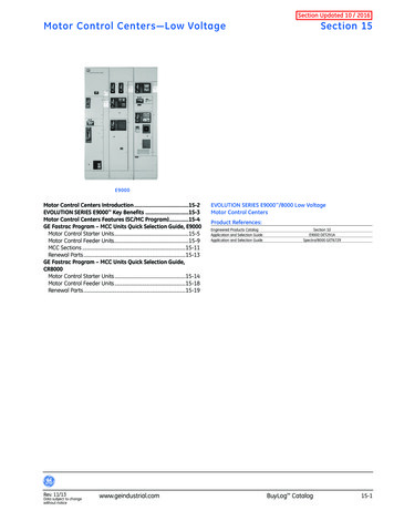
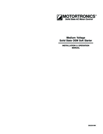
2.3 - 7.2kVCustomer ProvidedMomentary or MaintainedStart / Stop SwitchingMaintained2.2 Control Connections - TCB (Terminal and Control Board)STARTFor a larger view of this picture, see page 73.STOPFuses2.2.1 TCB BoardF1: Control Fuses for TB1 1 - 9Part #ACG1A250VAC or equivalentF2: Contactor and relay output fusesPart #ACG4A250VAC or equivalentF3: TB2 Pin #6Part #ACG4A250VAC or equivalentThe TCB board provides interconnectionsbetween the main power and CPU boards andthe customer’s control logic connections. It isa 120 VAC control board with several auxiliarydry control contacts, built-in time delay circuitsand emergency bypass functions. It alsocontrols the sequence of the inline isolationand bypass contactor and provides provisionsfor shutdown interlocks. (see section 2.2.2)MomentaryMBTB2TB9MVC3 - TCBAux StartOutput120 VACNeutralTB1T1OptionalInterlocks2.2.2 Description of Terminal ConnectionsTB1120 VACSourceF1#4#5 #6 #7 #8 #9 #10 #11 #12NC C NC CNO AC C NO NCMBINTERLOCK STOP START NEUT TB2F2FACTORY WIREDDO NOT USEF3TB2Start/Stop ControlFigure 2-1Emergency Bypass/Full Voltage StartTB6FAULTDCU CONNECTIONS ONLYTB3LOCK OUTStart/Stop Control - Terminal Block 1 (TB1) : Positions 2-3 and 4-5 have factory jumpersinstalled and can be removed for customer’snormally closed, dry, shutdown contacts (SeeFig 2-1 above). Positions 6-7-8 are for either two wire or threewire start/stop logic. Two wire is connected topositions 6 and 8 with a N.O. dry, maintainedstart/stop contact. Three wire control connectsto 6 with 7 as the stop push-button, and thestart push-butto
MOTORTRONICS Solid State AC Motor Control . Setpoint Page 12 Displays - System Setpoints 55 2.3 Optional RTD Board 13 5.2 Setpoint Page 13 Displays - Calibration &Service 57 . Run, Alarm, Trip, Aux Relays Remote Mount Capability Up to 1000 circuit-feet from chassis (use twisted, shielded wire & power source)