Transcription
CEDINSTALLATION,OPERATION&PROGRAMMING MANUAL
Table of ContentsPageChapter 1: IntroductionChapter 2 - InstallationChapter 3 - Motor Overload ProtectionChapter 4 – ConnectionsChapter 5 – ProgrammingChapter 6 - Start-upChapter 7 - Fault ConditionsAppendices1.1General Description 11.2Sizes and Ratings .42.1Receiving and Unpacking 52.2Choosing a Location .52.3Initial Unit Inspection .52.4SERVICE WARNING! .62.5Mounting and Cleaning 62.6Terminations . .72.7Remote Keypad Mounting.72.8Dimensions .83.1Solid State Overload Protection .93.2NEMA Class Trip Curves .114.1Line Power Connections . .134.2Control Connections .165.1Introduction .205.2Digital Interface .205.3Display Modes 215.4Program Mode 225.4.5Fault Mode 255.5The RX Function List 275.6Function Descriptions .355.6.1Motor and Overload Functions 355.6.2Current Protections 385.6.2.aGround Fault Protection.405.6.3Voltage Protections. 415.6.4Phase & Frequency Protections.435.6.5Motor Power Protections . .455.6.6Lockouts / Inhibits .475.6.7Output Relays . .485.6.8Motor Running Detection.495.6.9Process Timer/Time Clock Control .495.6.10Communications 505.6.11External Input .515.6.12System Settings .515.6.13Auto Reset and Auto Restart 555.6.14Factory Firmware 575.6.15Timer Value Readouts 585.6.16Fault History and Statistical Data.595.6.17Relay 1 Fail Safe Programming 615.6.18ZCT . 625.6.19Alarms . 626.1Basic Startup 636.2Start-up Check List .647.1Fault Codes and Numbers 65Appendix A: Parameter Lock / User Password Instructions Appendix B: Process Control Timer Functions .Appendix C: Ground Fault Installation Test Instructions . . .Appendix D: Relay Settings Record. . .Appendix E: RX Zero Sequence Ground Fault CT Option .Appendix F: Modbus RTU Communication and RX Registers . .Warranty Information 6870788086891100
RX SeriesDigital Solid State Protection Relay 5 - 2000AChapter 1 - Introduction1.1 General DescriptionThe RX Series is a digitally programmable solid-state motor protectionrelay. The RX Series features an advanced solid-state overload relay,that provides much more than protection for your motor and load.Designed to be versatile, it can be used in any 3 phase motor controller,configuration including Across the Line (DOL), Reversing, 2 speed,electro-mechanical Reduced Voltage, Wye-Delta (Star-Delta) and SolidState Soft starters. The RX Series includes a programming keypad toset operating parameters for ideal starting and protection features, pluseasy to understand diagnostic LEDs. Built-in Metering features canreduce the amount of separate components necessary for completemotor monitoring. An integrated Batch Process Timer and Time ClockController can be used for automated applications. The RX Series canaccept 85 – 265VAC control power from any source withoutadjustments or settings and can use a dry contact input for Start / Stopcontrol. A line voltage of up to 600V can be directly input, or PTs can beused for up to 15kV motors. Current can be directly monitored up to75A, or up to 1200A through external CTs.1.1.1Advanced Motor Protection FeaturesThermal Model ElectronicOverload ProtectionA sophisticated Thermal Model of the motor operation is created in themicroprocessor to accurately track all starting, stopping andrunning conditions to provide maximum motor protection.Retentive ThermalMemoryOverload circuit retains thermal condition of the motor regardless ofcontrol power status. Unit uses real time clock to adjust for offtime.Starting: Programmable for Class 5 thru 30Two StageOverload CurvesRun: Programmable for Class 5 through 30 when "At-Speed" isdetected.Programmable Run Detection: Auto or Auto / TimedAuto Method: I 150% FLA x SF, then I 100% FLA x SFAuto / Timed: 1 – 180 seconds or Auto, whichever occurs firstOverload ResetManual (default) or automaticDynamic Reset Tracking. Overload will not reset until thermal capacityavailable in the motor is enough for a successful restart. Relaylearns and retains this information by monitoring previoussuccessful starts.Acceleration ProtectionAcceleration Time Limit: 0 – 300 secondsFor protection against mechanical problems or incompletesequence on Reduced Voltage Starters.Stall Detection Trip Level: 100 – 600% FLA with 1 – 20 second delay.Current ProtectionOver Current Trip Level: 50 - 300% of motor FLAUnder Current Trip Level: 10 –90 % of motor FLACurrent Imbalance Trip Level: 5 - 30% Imbalance in any two phasesPeak (short circuit) Current Trip: 800 – 1400% FLACurrent Trip Delays: 1 -20 seconds1
RX SeriesDigital Solid State Protection Relay 5 - 2000A1.1.1Advanced Motor Protection Features (continued)Voltage ProtectionOver Voltage Trip Level: 1 – 10% of Line VoltageUnder Voltage Trip Level: 1 – 20% of Line VoltageSeparate levels for Start and Run modesVoltage Imbalance Trip Level: 1 – 30% Phase DifferenceVoltage Trip Delays: 1 – 20 secondsPhase ProtectionPhase Loss Trip: Any phase current less than 12% of CT.Phase Rotation Trip: ABC, ACB or insensitive.Over Frequency Trip: 1 – 10Hz programmed frequencyUnder Frequency Trip: 1 – 10Hz programmed frequencyPhase Protection Trip Delays: 1 -20 secondsEquipment Ground FaultProtectionType: Residual Current TripRange: 5 – 90% of unit CT ratioTrip Delay: 1 – 60 secondsPower ProtectionUnder kW Trip Level: 20 – 100% of calculated motor kWkW Trip Delay: 1 – 9999 minutesPF Trip Setting: Lead, Lag or Lead/Lag, Normal or Reversed currentdirectionPF Trip Level: 0.01 – 1.0 (cos. θ)Starting Inhibit ProtectionCoast Down (Back Spin) Lockout: Coast Down Time Range: 1 – 60minutesStarts-per-hour Lockout: 1 – 10 successful starts per hourMinimum Time between Starts Lockout: 1 – 60 minutes between startattemptsRestart DelaySequential Start Feature for restarting delay after a power outage.1-999 seconds after a power lossAuto ResetCan be programmed to attempt resetting after selected faults (12settings)0 – 10 Attempts, 2 minutes delay between attempts1.1.2Control FeaturesMotor Control2 Programmable Output Relays:1 form C (SPDT), 1 form A (SPST), programmable to 33 functions22 Trip functions, 4 Inhibit functions, 3 status functions and 1Control function1 Isolated external Input for External Trip or Start Command orTrip ResetProcess Timer(2 modes)Minimum Batch Timer: Runs until timer expiresPermissive Run Timer: Runs only during specified timesTime Range: 0 - 9999 minutesReal Time Clock (RTC)Controller24/7 Time Clock Controller, works with Process Timer for run timeTime Range: 1-24 hoursCycle Setting: 1- 7 days per weekEvent Settings: 1 - 7 start events per day2
RX SeriesDigital Solid State Protection Relay 5 - 2000A1.1.3Metering FeaturesCurrent MeteringA, B, C phases individually or Average of all three phasesGround Fault CurrentVoltage MeteringA-B, B-C or C-A phase voltageAverage of all three phasesPower MeteringMotor kW (or MW)Motor kVA (or MVA)Motor kVAR or (MVAR)Motor Power FactorLeading (inductive) or Lagging (capacitive) indicationPhase MeteringCurrent Imbalance percentageVoltage Imbalance percentageRotation SequenceFrequencyReal Time Clock BasedMetering andUse StatisticsMotor Remaining Thermal CapacityThermal Capacity to ResetRestart Delay Time after a power failureCoast Down Inhibit TimeTime Between Starts Inhibit TimeProcess Timer Elapsed Time24hr Time Clock Controller TimekWH (or MWH) power usageMotor Running Time (Elapsed Time Meter): 0 – 9,999,999.9 hrs.Motor Run Cycle Counter: 0 – 99,999,999 cycles1.1.4Electrical RatingsType of Load:Three phase AC induction motorsAC Supply Voltage:Direct Input: 208 - 600VACPT Input: .6 – 15kV (customer supplied PTs, 120V secondary)Tolerance: 10%Frequency: Programmable for 50 or 60HzPower Ratings:Direct Input: 1 – 75A AmpsCT Input: 75 – 1200A using optional or customer supplied externalCTs with 5A secondaryPhase RotationOperates with any phase sequence (insensitive)Programmable rotation trip ABC / ACBAmbient Condition DesignOperating Temperature: 0 to 50 C (32 to 122 F)Humidity: 5 - 95% relativeAltitude: 0 - 3300 ft. (1000m) above sea level without deratingControl Power85 - 265VAC (customer supplied), no adjustments necessaryInputs1 Dry (voltage free) contact input for Start or External TripUses 6VDC from an internal power supply2 Programmable Outputs1 each Form A (SPST), Fail Safe (configurable), 10A 250VAC,resistive, also rated 1/3HP (10.0 LRA) at 120VAC1 each Form C (SPDT): 5 Amps, 250VAC max. (1200VA) resistiveCan be programmed for 33 functions, with trip delaysRelay Test: Energize (force) either relay or both.ApprovalsUL Listed, Canadian UL (cUL) Listed CE Approved1.2Sizes and RatingsThe Motortronics RX Series protection relays are current rated. Max.Amp ratings are for continuous duty and must not be exceeded. Alwayscheck the motor nameplate FLA and Service Factor to ensure proper3
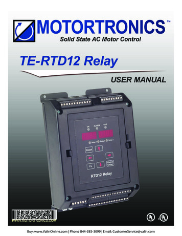
RX SeriesDigital Solid State Protection Relay 5 - 2000Asizing.Each size has an adjustable range of current from 50% to 100% of theunit’s max. current rating. Motors that are smaller than the lowest settingcan be accommodated by using Primary Turns (see section 4.1.2 fordetails).Current Range(direct reading)ModelNumberCurrent Range(using Primary Turns)Min. - Max.Min. - Max.RX-52.5 - 5A1 – 2.5A (5 turns max.)RX-4020 - 40A10 – 20A (4 turns max.)RX-7538 - 75A---Table 1.2: RX Series SizesDisconnectThe RX-5-P is alsodesigned to be used with external CTs for motorsor the 75A limit of a stand-alone relay. Seewith FLA ratings beyondChapter 4 for additionaldetails.CircuitBreakerR / L1L1S / L2L2T / L3L3MotorController.MCU / T1NOTE: CT Grounding IsFor CE ComplianceV / T2W / T35AExternalCTsMTRFigure 1.2: RX-5-P used with external CTs for larger motors4
RX SeriesDigital Solid State Protection Relay 5 - 2000AChapter 2 - Installation2.1Receiving and UnpackingUpon receipt of the product, you should immediately do the following: Carefully unpack the unit from the shipping carton and inspect it forshipping damage (if damaged, notify the freight carrier and file aclaim within 15 days of receipt). Verify that the model number on the unit matches your purchaseorder. Confirm that the ratings label on the unit matches or is greater thanthe motor’s HP and current rating.2.2Choosing a LocationProper location of the RX Series is necessary to achieve specifiedperformance and normal operation lifetime. The RX Series shouldalways be installed in an area where the following conditions exist: Ambient operating temperature:Panel (open chassis) unit: 0 to 50 C (32 to 122 F)Enclosed unit: 0 to 40 C (32 to 104 F) Protected from rain, moisture and direct sun. Humidity: 5 to 95% non-condensing Free from metallic particles, conductive dust and corrosive gas. Free from excessive vibration (below 0.5G) Units must be mounted in the appropriate type of enclosure.2.3Initial Unit InspectionMake a complete visual check of the unit for damage that may haveoccurred during shipping and handling. Do not attempt to continueinstallation or start up the unit if it is damaged. Check for loose mechanical assemblies or broken wires which mayhave occurred during transportation or handling. Loose electricalconnections will increase resistance and cause the unit to functionimproperly. Prior to beginning the installation, verify that the motor and RXSeries unit are rated for the proper amperage and voltage.5
RX SeriesDigital Solid State Protection Relay 5 - 2000A2.4SERVICE WARNING!Do not service equipment with voltage applied! The unit can be thesource of fatal electrical shocks! To avoid shock hazard,disconnect main power and control power before working on theunit. Warning labels must be attached to terminals, enclosure andcontrol panel to meet local codes. Use Lock Out tags such as theone shown when servicing equipment.2.5Mounting and CleaningThe RX Series is designed to snap onto standard duty DIN rail, or tomount directly to a panel with #8 screws (4mm). When drilling orpunching holes in an enclosure containing an RX Series relay, cover theelectrical assembly to prevent metal filings from becoming lodged inareas which can cause clearance reduction or short circuits. After workis complete, thoroughly clean, vacuum the area, and re-inspect the unitfor foreign material.2.5.1 ClearancesMake sure there is sufficient clearance all around the unit for cooling,wiring and maintenance purposes. To conserve panel space, the RXSeries was designed for close clearances. A minimum clearance of 1”(25 mm) on all sides is necessary to maximize effective airflow andcooling keeping in mind that these are minimums. Wiring may requiremore clearance, particularly on the bottom of the unit.Othe r Dev ice s,i.e . M otor Starte r1" minimum (25 mm)RX SeriesRelay1" minimum (25 mm)Figure 2.5: RX minimum mounting clearances6
RX SeriesDigital Solid State Protection Relay 5 - 2000AWARNING!Remove all sources of power before cleaning the unit.In dirty or contaminated atmospheres, the unit should be cleaned on aregular basis to ensure proper cooling. Do not use any chemicals toclean the unit. To remove surface dust use clean, dry 80 to 100 psicompressed air only. A high quality, dry paintbrush is helpful to loosenup the dust prior to using compressed air on the unit. Do not use wirebrushes or other conductive cleaning materials2.6TerminationsAll line and control power terminations are to be made to the platedsaddle clamp terminals located on each unit. Motortronics recommendsusing crimp-on terminals wherever practical. Motor current conductorscan feed through the built-in CT holes at the base of the relay.The RX-5-P also comes with a Line-Load Power Terminal block thatpermits separate Line and Load power connections to be made with upto 12 gauge wire. This unit can be removed to provide access to thefeed-through CT holes if desired.Note: All wiring must be sized according to local code standards.2.7Remote Keypad MountingThe keypad / operator interface unit can be remotely mounted up to 6’(1.8 meters) away from the relay, i.e. on an enclosure door. A remotemounting kit is not necessary for Type 1 enclosures. A keypad kit isavailable for Type 4, 4X and 12 applications. A standard DB-9connection cable (computer serial cable) is needed for thecommunications link. Cables can also be made by the user withstandard DB-9 connectors, Male for the keypad, Female for the baseunit. The standard keypad can be mounted using 4 small # 6 (M3)screws (customer supplied) and a 7/8” (22mm) hole to accommodatethe DB-9 connector. The Type 4, 4x, 12 keypad kit is mounted with asupplied and approved adhesive backing.DB-9MRX Relay baseDB-9FFigure 2.7.aKeypad Rear Viewfor remote mountingFigure 2.7Remote Keypad Mounting KitComponentsCable,Up to 6 feet (1.8m)7
RX SeriesDigital Solid State Protection Relay 5 - 2000A2.8DimensionsNote:Drawing shown is the RX-5-P with LineLoad Termination Adaptor.For Feed- through versions, use thisdimension.Figure 2.8.a: Feed-Through base unit example.Figure 2.8: RX Dimensions8
RX SeriesDigital Solid State Protection Relay 5 - 2000AChapter 3 - Motor Overload ProtectionMOTOR FLA (F001)must be programmedfor unit to operate!3.1Solid State Overload ProtectionThe RX Series Relay provides true U.L. listed I2t Thermal OverloadProtection as a built-in function of the main digital processor formaximum motor protection. It simulates the tripping action of a bimetallic overload relay, with the accuracy and repeatability of a digitalcontrol system. It is adjustable over a wide range and can be easilyprogrammed for different trip curves.3.1.1 Thermal MemoryThe RX Series microprocessor uses a sophisticated “Thermal Register”in the digital memory to keep track of motor heating and cooling overtime regardless of the relay’s power status. By using non-volatilememory, the RX Series will not “forget” that the motor has been runningeven if power to the relay has been turned off and back on. Continuousoverload protection is provided based on the true thermal condition ofthe motor.Examples:H 100100% Thermal Capacityremaining at restH 05757% Thermal Capacityremaining after starting(43% used)3.1.2 Thermal CapacityThe Thermal Register is displayed as a percentage. This percentage isthe motor’s remaining thermal capacity. The percentage value begins at100, showing that the motor is cool (has 100% of its capacity available).As the motor heats up or moves toward an overload condition, thepercentage begins to drop. The Thermal Capacity is derived from theprogrammed motor nameplate Full Load Amps (FLA) in Function F001,the Service Factor rating in Function F002, and the Overload Trip Classin Functions F003 and F004. Setting these functions to the propervalues provides maximum protection and eliminates nuisance tripping.The Remaining Thermal Capacity can be viewed by using the UP orDOWN arrow keys when in the Status Display mode. From the defaultPhase A Current screen (dot on right side), press the UP arrow key todisplay [H100] meaning there is 100% of the Thermal Capacity (H Heat capacity) remaining in the motor. After starting or running, themotor will use this capacity and the display will show a lower number.For example, after a cold start, the display may read [H065] whichindicates that the motor has 65% of its thermal capacity remaining (35%used). The Status Display screens cycle back to the beginning, so theDown arrow keys can get to this display as well. 3.1.2.aMotor Full Load (FLA) SettingUse Function F001 to enter motor FLA as indicated on the motornameplate. (Do not calculate for service factor, this is programmedseparately in F002).Note:All RX Series relays are shipped from the factory with F001 set to adefault value of 0000. If F001 is left at the factory default, the unitwill not operate. If the user attempts to start the RX Series withoutentering the motor nameplate FLA, the relay will Fault and thedisplay will read “nFLA” (no Full Load Amps).9
RX SeriesDigital Solid State Protection Relay 5 - 2000A3.1.3 Disabling the Overload ProtectionThe Overload Protection feature can be disabled if necessary. Whenusing external devices such as Motor Protection Relays or when the RXSeries is used only for other features, this feature can be disabled toprevent conflicts with other overload protection devices. To disable theOverload Protection function, use F005.WARNING!Do NOT disable Overload Protection unless another ThermalOverload Protection device exists in the circuit for all threephases. Running a motor without Overload Protection presents seriousrisk of motor damage or fire. 3.1.3.aManual ResetThe factory default setting is Manual Reset. This means that whenthe Overload Trip is activated, the starter cannot be restartedwithout pressing the Reset key. The Overload Trip will not resetuntil the motor cools down (see 3.1.3.d). The Manual Reset functionis also “trip free”. Holding in the Reset key will not prevent theOverload Trip from activating and protecting the motor.Note:When the Overload Trip activates, the Overload LED will glow solid.When the motor cools down, the LED will begin to flash, indicatingthat the Overload Trip can be reset. 3.1.3.bAutomatic ResetIf Automatic Reset is necessary, change from Manual Reset toAutomatic Reset by using Function F005. (See Section 5 fordetails). In this mode, a 3-wire control circuit will be capable ofrestart when the RX Series has reset itself after the cool downperiod.WARNING!Two-wire control systems may restart without warning when AutoReset of the overload protection is selected. Extreme cautionshould be exercised. To prevent automatic restarting with 2-wirecontrol systems, use external interlocking to provide sufficientwarning and safety to operators. A Warning Label similar to thatshown below (and the one provided in the packet with this manual)must be located where visible (on the starter enclosure and/or thedriven equipment) as required by local code.WARNING: MOTOR CONNECTED TO THIS EQUIPMENTMAY START AUTOMATICALLY WITHOUT WARNING10
RX SeriesDigital Solid State Protection Relay 5 - 2000A 3.1.3.dDynamic Reset CapacityThe RX Series includes the ability to dynamically track the ThermalCapacity needed for a successful restart after an overload trip. Itaverages the Thermal Capacity consumed in the previous threesuccessful starts, and calculates a Thermal Capacity to Start(viewed in Function F086). After tripping on Overload, the ThermalRegister must have regained the amount recorded in F086 before aReset will be allowed. If the display reads [ Inh] when attempting toreset an overload trip, it is indicating that the relay is Inhibited frombeing reset.Refer to details of Function F071 for information on emergencyoverride of lockouts such as this.3.2NEMA Class Trip CurvesNEMA Class trip curves are based on a common tripping point of 600%of motor Full Load Amps (FLA). Curves vary by the amount of timebefore the unit trips. As an example, a Class 20 curve will trip in 20seconds at 600% of FLA. The factory default setting of Class 10 will tripin 10 seconds at 600% of FLA.3.2.1 Dual Overload Trip CurvesThe RX Series Soft Relay provides two separate Overload TripProtection Curves, one for starting and one for running conditions. Therelay’s At-Speed detection circuit determines when the motor hasreached full speed (see Fn F049, section 5.6.8). When the At-Speedcondition is reached, the overload trip curve will shift from the Start tothe Run level, as programmed in Functions F003 and F004. SeeSection 5.6.1 for programming details.3.2.2 Starting Overload Trip CurveDuring the start mode, Overload Trip Curves are selectable from NEMAClass 5 through Class 30. The default setting of Class 10 allowsprotection for the overload capacity of the soft relay as well as themotor. Use a higher Trip Class only if nuisance tripping occurs with thedefault setting.3.2.3 Running Overload CurveDuring the Run mode, Overload trip curves are selectable from NEMAClass 5, 10, 15, 20, 25, and 30. Program the appropriate curveaccording to the characteristics of your motor and load.11
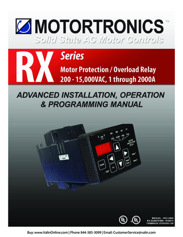
RX SeriesDigital Solid State Protection Relay 5 - 2000A3.2.4Overload Trip Curve ChartFigure 3.2.4: RX Series Overload Trip Curves12
RX SeriesDigital Solid State Protection Relay 5 - 2000AChapter 4 – Connections4.1Line Power ConnectionsConnect appropriately sized power conductors to the base unit inputterminals marked L1, L2, L3 (R, S, T for IEC users) underneath thekeypad. These will be for Line Voltage Sensing, not for the motor load(see below), but should be fuse protected for 5A max. Avoid routingpower wires over the display.4.1.1 Motor Power ConnectionsMotor power connections vary for different sizes.On the RX-5, the user has 2 choices; Separate Line and Loadconnections to terminals on the relay base, or Feed-Through wiring.Use the Separate Line and Load connections when the motor is smallenough ( 5A FLA) to be connected directly to the terminal block screwson the base.DisconnectorCircuitBreakerR / L1S / L2T / L3MotorControllerExample.MCU / T1V / T2W / T3Figure 4.1.1.a:RX-5-E Basic Connectionsfor Large Motors5AExternalCTsNOTE: CT Grounding IsFor CE ComplianceMTR4.1.1.a Large Motor Connections. The RX-5 is also used for largemotors where external CTs are necessary to step the motor currentdown to 5A. Simply pass the motor leads through the external CTwindows, then connect the CT secondary conductors to the RX-5terminal adaptor (or pass them through the internal CT windows). Youmust also reprogram Function F073 for the external CT ratio in order forthe RX to function properly for the higher motor currents13
RX SeriesDigital Solid State Protection Relay 5 - 2000ADisconnectorCircuitBreakerR / L1S / L24.1.1.b Motor Power Connections (continued)On the RX-40 and RX-75, the user can just pass the motor leadconnections through the internal CTs of the RX Series relay basewithout making connection directly to the relay. This can also be donewith the RX-5 by removing the connection adaptor.Figure 4.1.1:RX-40 and RX-75Basic ConnectionsT / L3MotorController.MCU / T1V / T2W / T3RXRelayBaseRXRelayBaseInternalCTsMTRMTRFigure 4.1.1.aExample of 2 primary turns through internal CT(only Phase A shown for clarity)4.1.2 Using Primary Turns to Increase Range.The RX relay can be used to read motor currents lower than thestandard rating of the unit by increasing the current read by the CTsthrough the use of “Primary Turns”. Each “turn” refers to the number oftimes that the power conductor is passed through the CT core. 2 passesthrough the core is referred to as 2 Primary Turns, also meaning thatthe current read by the CT is increased 2 times (2x). 4 Primary Turnswould then mean that the motor conductors pass through the CTs 4times and the current read is 4x the CT current. Another way to look at itis that the relay range has been divided by the number of turns. Forexample, if the motor FLA is between 5A (upper limit of the RX-5) and20A (lower limit of the RX-40), use the RX-40 and loop the appropriatenumber of turns through the built-in CT windows. For loads from 5 -10A,loop the motor leads through 4 times (4 “turns”). The max. amp rating isnow 40 4 or 10A, so the range is 5 – 10A. For loads 10 – 20A, use 2Primary Turns through the windows for a rating of 40 2 or 20A, so thenew range is 10-20A. This doubles or quadruples the range of the relay,but must be coordinated by programming the correct number ofturns into F074 (see section 5.6.12.a for additional information).14
RX SeriesDigital Solid State Protection Relay 5 - 2000A4.1.2 Using Primary Turns to Increase Range (continued)In general when using external CTs, it is always best to choose a CTratio that works out to have your motor FLA fall within the range ofadjustment of the RX relay. Unfortunately this cannot always beaccomplished with the available components. So Primary Turns canalso be used with external CTs to increase the range of the RX relay forFLA’s of motors that fall outside of its settings. For instance, if a motorhas 240FLA, and you must use an external CT rated 500:5, the 5A CTcurrent will represent a maximum of 500A, but the relay can only beturned down to 2.5A, so the lowest adjustment would be 250A, abovethe motor FLA. To achieve proper protection, pass the 5A CT currentthrough the relay CT windows twice (2 turns). The 5A external CTcurrent now represents 250A, so the range of adjustment becomes 120– 250A, which properly covers the motor nameplate FLA.Remember when doing this to always program the External CTratio into Function F073, as well as the Primary Turns into F074.This allows your display and protection settings to accuratelyrepresent the actual motor power readings. See section 5.6.12.a fordetails on programming those functions.4.1.3 Power Factor Correction CapacitorsPower factor correction capacitors can be connected to motorscontrolled by RX Series relays, however because the RX Seriesmeasures power factor for several functions, the PFC capacitors shouldbe connected downstream (after) of the relay.4.1.4 GroundingThe RX Series relay is designed in a totally insulated case for use in a‘floating ground” condition, therefore there are no grounding provisionsprovided or necessary.4.1.5 TestingThe RX Series can be tested by forcing the relay contacts. See FnF111 in section 5.6.18 for more details.15
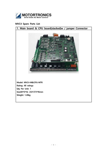
RX SeriesDigital Solid State Protection Relay 5 - 2000A4.2Control ConnectionsControl connections on the RX Series relay are divided into 2 groups.With the unit oriented vertically, TB1 is a 5 connection terminal block (onthe top), and TB2 is a 7 connection terminal block (on the bottom).Following are descriptions of control connection points.TB-1TB-2Figure 4.2: Control Terminal Blocks4.2.1 AC Control Power Supply ConnectionA separate AC Control Power supply is required to power theelectronics of the RX Series relay. The control power input must befrom 85 to 265VAC, either 50 or 60 Hz, and must be connected toterminals marked “AC IN 120/240VAC” of TB-2. These terminals are theequivalent of A1 and A2 in IEC terminology, as shown in figure 4.2.1below. This control voltage must be customer supplied.AC ControlPow er Supply80 - 265VAC, 50/60 HzL1L2L3(A1)( A2)(not marked this way, but also notpolarity sensitive)Figure 4.2.1Control Pow er Supply ConnectionTB-1Control Power RequirementsThe RX Series uses very little control power, less than 10 watts totalwhen operating. The RX relay is internally fused at 125mA.16
RX SeriesDigital Solid State Protection Relay 5 - 2000A4.2.2 Control ConnectionsThe output relays from TB2 have different power ratings. Relay 1 isdesigned for higher power operation, 10A@ 240VAC resistive orinductive and carries a 1/3HP rating at 120VAC (max. 10.0 LRA). Relay2 is rated 5A@ 240VAC resistive, 1200VA maximum and is not rated fordirect switching of motors. Both relays must be protected from currentsin excess of their ratings, either with a fuse or with other suitable currentprotection devices.Figure 4.2.2Control ConnectionsTB-2RELAY 1NO COMMax. 10A 240VAC1/3HP (250W)Inductive loadNORELAY 2NC COMISOINPUTMax. 5A 240VAC1200VA4.2.3 Two Wire Isolated Input / PLC ConnectionAn Isolated Input is provided that can be used with a dry contact from aswitch, a relay, or a relay output of a PLC. This input can beprogrammed as an External Trip input, a Start command input for use inconjunction with the Process Timer and/or Time Clock Controllerfunctions, or as an
RX Series Digital Solid State Protection Relay 5 - 2000A 1 Chapter 1 - Introduction 1.1 General Description The RX Series is a digitally programmable solid-state motor protection relay. The RX Series features an advanced solid-state overload relay, that provides much more than protection for your motor and load.