Transcription
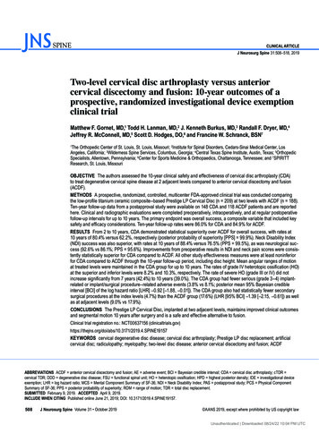
Cervical SolutionsROI-C Cervical CagewitherteBRIDGE P L AT I N G T E C H N O LO G YSurgical Technique Guide
2ROI-C Cervical Cage—Surgical Technique GuideROI-C featuring VerteBRIDGE plating is a zero-profile,stand-alone* cervical cage, with streamlinedinstrumentation and surgical technique,requiring minimal exposure.* In case of trauma, vertebral instability, or significant bone removal, the ROI-C implant should be augmented with additional supplemental fixation.
3ROI-C Cervical Cage—Surgical Technique GuideTABLE OF CONTENTSROI-C Cervical Cage Overview4Preparation and Access5Distraction and Discectomy6Trialing7Implant InsertionDepth Stop SelectionImplant Holder ComponentsImplant Holder AssemblyImplant Connection to Implant HolderImplant Positioning99101011Plate Insertion(Optional) Starter Awl Selection(Optional) Starter Awl Assembly(Optional) Starter Awl InsertionVerteBRIDGE Plate SelectionPlate Reference TableFirst Plate Insertion(Optional) Second Starter Awl InsertionSecond Plate InsertionImplant Holder Removal and Final Assessment121213141415171920Implant Revision21Implant Kit24Starter Awl Plate and VerteBRIDGE Reference Tables25Instrument Set26Important Information on the ROI-C Cervical Cage28Zimmer Biomet Spine does not practice medicine. This technique was developed in conjunctionwith health care professionals. This document is intended for surgeons and is not intended forlaypersons. Each surgeon should exercise his or her own independent judgment in the diagnosisand treatment of an individual patient, and this information does not purport to replace thecomprehensive training surgeons have received. As with all surgical procedures, the techniqueused in each case will depend on the surgeon’s medical judgment as the best treatment for eachpatient. Results will vary based on health, weight, activity and other variables. Not all patients arecandidates for this product and/or procedure.
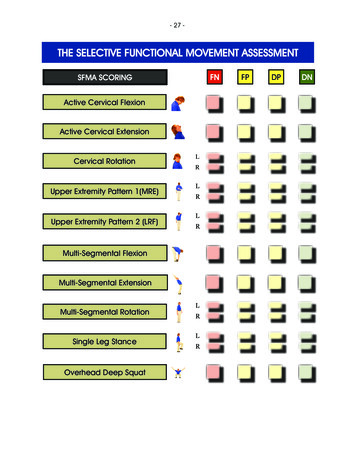
4ROI-C Cervical Cage—Surgical Technique GuideROI-C CERVICAL CAGE OVERVIEWDepth12 mmAnatomicFeatures a superior edge that complements healthyendplate contours.Depth14 mmWidth14 mmWidth15.5 mmWidth17 mmLordoticDesigned to allow close contact with the bone of patients withflattened endplates.4 FootprintsBroad offering to adapt to various patient anatomies.The ROI-C Cervical Cage withVerteBRIDGE plating offers a sleek andminimalistic stand-alone* solution.Streamlined instrumentation functionsin-line with the disc space, requiringminimal exposure, while an innovativeimplant design leaves minimalhardware in the patient, all withoutsacrificing stability.The ROI-C Cervical Cage is available in a variety offootprints designed to meet varying patient anatomies.The cage accommodates integrated, self-guided,self-locking VerteBRIDGE plating designed toprovide stability with no instrumentation protrudinganterior of the vertebral bodies. The self-guided,curved VerteBRIDGE plates are delivered in the planeof the disc through a direct anterior approach, sothat the surgery can be achieved with less exposurethan may be required to implant a traditional cervicalplate, or even contemporary stand-alone systemswith screws that must be inserted at oblique andchallenging angles.** In cases of trauma, vertebral instability, or significantbone removal, the ROI-C implant should beaugmented with additional supplemental fixation.The system features thoughtfully designedinstrumentation including an inserter that protectsanatomical structures when placing the cage andVerteBRIDGE plating.
5ROI-C Cervical Cage—Surgical Technique GuidePREPARATION AND ACCESSC-ArmMayo StandC-Arm MonitorFigure 1Patient positioningSTEP 1 Review and inspect all instrumentation and implantsprior to sterilization. Replace or add any necessary components for theplanned surgery. Surgeon must be fully experienced with the requiredspinal fusion techniques. Position and drape the patient in the usual fashion(Figure 1). Expose the affected levels via a standard incisionand tissue dissection. Place any retraction pins in locations that will allowfor the planned implant and instrumentation. Perform any necessary bone and tissue removal. Prepare vertebral endplates via the use of acombination of curettes, rasps, osteotomes,disc shavers or rongeurs to remove disc materialand cartilage.
6ROI-C Cervical Cage—Surgical Technique GuideDISTRACTION AND DISCECTOMY7 mmFigure 3aAnatomic cage7 mmFigure 2Caspar distractorFigure 3bLordotic cageSTEP 2Perform a thorough discectomy to remove the discdown to the osseous endplates. Prepare the endplatesjust enough to create a surface that will encouragevascularization between the endplates and the graftwithout weakening cortical bone.After the discectomy, distract as necessary to achieveadequate access to the disc space.If using a caspar distractor, the pins should be placedapproximately 7 mm from both endplates to avoidcontact between the caspar pins and ROI-C anchoringplates during insertion (Figure 2).If patient anatomy doesn’t allow 7 mm of space, thenremove the caspar pins prior to plate advancement toeliminate any risk of plate obstruction.During the discectomy, consider the two availableimplant profiles: ROI-C Anatomic: Designed with a curved superiorsurface that compliments healthy endplate contours.The anatomic implant has a 6 of built-in lordosis.ROI-C anatomic’s design is available in both PEEKOPTIMA and titanium coated (Figure 3a). ROI-C Lordotic: Features a tapered profile forpatients with flattened endplates. The lordoticimplant has 7 of built-in lordosis. ROI-C lordotic’sdesign is available in both PEEK OPTIMA andtitanium coated (Figure 3b).
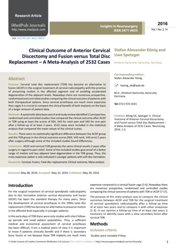
7ROI-C Cervical Cage—Surgical Technique GuideTRIALINGFigure 4Figure 5Depth gauge measurement: 14 mmTrialSTEP 3Depth AssessmentPlace the hook of the depth gauge (MB906R) just overthe posterior edge of the inferior vertebra.To achieve the most accurate reading, position thedepth gauge as medial as possible and completelyremove all anterior and posterior osteophytes. View the depth reading at the end of the depthgauge and determine if the 12 mm or 14 mm depthimplant will provide a more optimal fit (Figure 4).Using fluoroscopy, estimate the footprint and heightto best choose a trial. A trial can be placed in frontof the space to visually determine width. (Referencethe tables on page 24 for depth, width, and heightcombinations.)Trialing should begin with (Figure 5): The selection of implant profile: anatomic or lordotic. A conservative height not to exceed the height ofhealthy adjacent discs. A width that should extend to the uncinateprocesses, but should not ride up onto either uncus. A depth that leaves 1 mm of space from the anteriorand posterior vertebral borders.
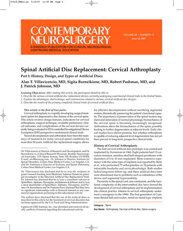
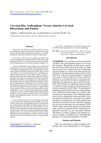
8ROI-C Cervical Cage—Surgical Technique GuideAnatomicLordoticFigure 6aTrial insertionFigure 6bLateral radiographic imagingThe ROI-C trials:Note: Without distraction, the trial should be snug inthe disc space even as the trial’s integrated handle isgently pulled away directly anterior from the vertebraeto assess fit. Should provide optimal endplate coverage, heightrestoration, and good segmental stability (Figure6a). Represent the dimensions of the implants. Are color coded by footprint size to match theimplant packaging’s color dot on the end of the box.Insert the selected trial into the space. Use lateralradiographic imaging to confirm trial sizing (Figure6b).Release the distraction in order to best assess thedisc space height and restore the best anatomic shapeof the operated space, as well as the best stability tothe implant.Note: Radiographic imaging is mandatory to confirmsizing. The hole through the trial should appear circular.An oval shape indicates possible rotation.Note: ROI-C trials are available with depth stops uponsurgeon request.
9ROI-C Cervical Cage—Surgical Technique GuideIMPLANT INSERTIONSMALL DEPTH STOPINNER THREADED RODLARGE DEPTH STOPIMPLANT HOLDERU-SHAPED DEPTH STOPDEPTH STOPTHUMB WHEELFigure 7aDepth stops sizesFigure 7bImplant holder componentsSTEP 4Depth Stop Selection (Figure 7a)Implant Holder Components (Figure 7b)The ROI-C system offers three depth stops: Inner Threaded Rod (MC9001R-2) Small Depth Stop (MC9001R-3) Implant Holder Body (MC9091R-1)–– width 5 mm x height 3.72 mm Large Depth Stop (MC9004R)–– width 8.2 mm x height 4 mm U-Shaped Depth Stop (SI-ROIC-0063)–– width 14.41 mm x height 6.35 mm Thumb Wheel (MC9001R-4) Depth Stop (Large shown here)
10ROI-C Cervical Cage—Surgical Technique GuideIMPLANT INSERTION (continued)BAABTHREADED RODCDCHOOKFigure 8aFigure 8bImplant holder assemblyImplant connection to implant holderImplant Holder Assembly (Figure 8a)Implant Connection to Implant Holder (Figure 8b)1. Load the thumb wheel (A) into the pocket on theinserter body. Hold thumb over wheel to maintainposition. Connect the selected implant to the implant holderby engaging the hook (A) on the holder with the slot(B) on the side of the implant.2. Slide the depth stop through the arch at the distaltip of the inserter (B) and into the thumb wheel.Capture the depth stop by rotating the thumb wheelclockwise (C), and adjust to 0. Once the hook is fully engaged, screw the knob (C)on the end of the holder to secure the implant withthe threaded rod.3. Load the threaded rod into the cannula of theinserter through the handle (D) and rotateclockwise to securely capture. The connection is fully secure when there is:–– No toggle in the connection.–– No gap visible between the knob and the handle. Load the central space of the implant with graft.Note: Overtightening of the threaded rod on the implantcould strip the PEEK threads and weaken the implant toholder connection.
11ROI-C Cervical Cage—Surgical Technique GuideFigure 8cFigure 8dAs needed, change the depth stop setting by 1 mm incrementsRadiographic imaging is mandatory prior to plate insertionImplant Positioning Start by setting the depth stop on the implantholder to 0 mm. When the stop is set to 0 mm, theimplant will be recessed from the anterior aspectof the vertebral body by 1 mm into the disc space(Figure 8c). Insert the implant into the disc space by gentlytapping on the end of the implant holder. Try to keepthe implant holder at a 90 angle to the disc spaceduring insertion. As needed, change the depth stop setting by 1 mmincrements for posterior adjustment, by turning theknurled wheel clockwise. Radiographic imaging is mandatory and should beused to make a final assessment of the implant depthand endplate coverage, prior to plate insertion. Atantalum marker is located 1 mm from the posteriorimplant edge for positioning reference (Figure 8d).
12ROI-C Cervical Cage—Surgical Technique GuidePLATE INSERTIONSTEP 1STEP 2STEP 5STEP 6STEP 3STEP 4STEP 7STEP 8Figure 9aFigure 9bStarter awl assemblyStarter awl assembly so that the blue retaining pin and sliding metalencasement labeled with a #1 are oriented upwardsSTEP 5Starter Awl Selection — OptionalStarter Awl Assembly — Optional The starter awl impactor (MC9097R) may be usedespecially when sclerotic bone is detected. Withthe cage in the final position, the awl may be used toinitiate the path for the VerteBRIDGE plates. Choose the proper starter awl plate size, andremove it from its packaging. Position the starterawl impactor so that both the blue retaining pinand sliding metal encasement labeled with a #1 areoriented upwards. Grasping the starter awl plateby the silicone protective cap, fasten it to the distalend of the starter awl impactor in the orientationdepicted in (Figure 9a). The starter awl impactor works with two differentsizes of sterile-packed starter awl plates, selectedbased on the height of the implant. Starter awlplates are not intended for implantation andshould be properly disposed of followingsurgery.–– Short (MC9095R-S) for implants with 5-7 mmheights–– Long (MC9096R-S) for implants with 8-10 mmheights Pull the starter awl plate distally to the end of thestarter awl impactor as depicted below, and removethe silicone cap. Slide the encasement forwardsso that the starter awl plate fits snugly into place(Figure 9b).
13ROI-C Cervical Cage—Surgical Technique GuideROI-C STARTER AWL IMPACTORMECHANICAL STOPFigure 9cFigure 9dInsertionValidate final starter awl plate positionStarter Awl Insertion — Optional Insert the shaft of the starter awl impactor into theROI-C implant holder’s groove. Orient the #1 onthe encasement so that it is visible, opposite of thebody of the ROI-C implant holder (Figure 9c). ROI-Cstarter awls are never to be used with ROI-C plateimpactors (MC9092R & MC9093R).Important: If the pins appear to be positioned wherethey could possibly impede the starter awl plates, removethe distractor and caspar pins before insertion. Insert the starter awl plate into the superior slot ofthe ROI-C implant holder head. If resistance is feltduring insertion into the slot, remove the starterawl plate and repeat the step. Use thumb pressureto bring the starter awl plate into contact with thebone. Start the insertion with three to four malletimpactions on the proximal end of the starter awlimpactor or until the starter awl plate is insertedroughly 50% of the way into the vertebral body. Extract the starter awl plate partially by reverseimpaction on the distal end of the impactionknob. Repeat impaction until the starter awl plateis 100% within the vertebral body, indicated bya full mechanical stop from the ROI-C implantholder, as depicted above. Validate plate positionradiographically (Figure 9d) and remove the starterawl plate through reverse impaction on the starterawl impactor knob.Important: It is important to prepare the secondvertebral body with the starter awl plate only afterinsertion of the first ROI-C locking plate. The pathway inthe second vertebral body must not be prepared at thesame time as the pathway in the first vertebral body.
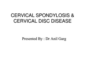
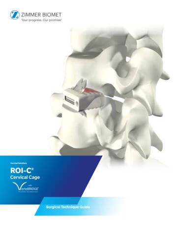
14ROI-C Cervical Cage—Surgical Technique GuidePLATE INSERTION (continued)11.4 mm9.8 mm8.1 mmPLATE HEIGHT8.1 mmANTERIORIMPLANT HEIGHTANTERIORBARWINGSRETAININGRIDGEFigure 10Figure 11Plate selectionPlate referenceAnatomic Plate Reference TableVerteBRIDGE Plate Selection Select the plate length according to the height of theimplant being used. Use the ROI-C standard plate(MC1005T) with heights 5-7 mm and the ROI-C longplate (MC1006T) with 8-10 mm heights.Implant Height(mm)Plate Size(Reference Number)H5H65.5StandardMC1005TH7H8Plate Height(mm)5.04.5LongMC1006T5.6Lordotic Plate Reference TableImplant Height(mm)Plate Size(Reference Number)H5H6Plate MC1006T5.44.9
15ROI-C Cervical Cage—Surgical Technique Guide#1 IMPACTORBONE/PLATECONTACTFigure 12Figure 13Load first plateAdvance first plateFirst Plate Insertion— Load First PlateAdvance First Plate Prior to inserting the first plate, release the distractorand caspar pins (if used), to allow compression ofthe construct. Using thumb pressure, insert the #1 impactor(MC9092R) to advance the first plate until it touchesbone (Figure 13). Take a lateral radiographic image toverify the plate is touching the bone. With the implant in the final position, load the firstplate into the cranial slot of the implant holder usingthe plate holder (MC901R). The plate paths crosswithin the implant holder so the plate inserted intothe cranial slot will be advanced into the caudalvertebral body (Figure 12).Note: The plates may be inserted into the cranial orcaudal slot for the first plate.Note: If the plate does not advance with thumb pressure,confirm the plate is properly loaded in the holder and that theholder is aligned with the PEEK.
16ROI-C Cervical Cage—Surgical Technique GuidePLATE INSERTION (continued)MECHANICAL STOPS#2 IMPACTORFigure 14aFully advance plateIMPACTION LINESFigure 14bFigure 14cFully advance plateImpaction linesAdvance First Plate (continued)Finalize First Plate Position Use a mallet to impact the first plate into the bone.The plate is fully advanced when the mechanical stopon the impactor meets the mechanical stop of theimplant holder (Figure 14a). Once position is confirmed, use the #2 impactor(MC9093R) to finalize the advancement of the firstplate. Again, the plate will have advanced completelywhen the mechanical stop on the #2 impactor meetsthe mechanical stop on the implant holder. Do not proceed to the #2 impactor until properplacement of the implant and first plate areconfirmed via fluoroscopy or x-ray (Figure 14b).Note: The impaction lines (Figure 14c) will allowvisualization of the plate’s advancement and themechanical stops should make contact when the linesappear aligned. Take a lateral radiographic image to ensure properimplant and plate position.Note: The plates must be advanced and finalized usingthis sequence:1st Plate2nd PlateAdvance with thumb pressureAdvance with thumb pressure#1 Impactor#1 Impactor#2 Impactor#2 Impactor
17ROI-C Cervical Cage—Surgical Technique GuideROI-C SECOND STARTER AWL IMPACTORFigure 15aFigure 15bSecond starter awl insertionSecond starter awl is roughly 50% into the vertebral bodySecond Starter Awl Insertion— Optional After full insertion of the first ROI-C locking plate,inspect the ROI-C starter awl plate for any damageand begin preparation of the second vertebral bodyin the same way as the first. Insert the shaft of the starter awl impactor into theROI-C implant holder’s groove as shown. Orient the#2 on the encasement so that it is visible, opposite ofthe body of the ROI-C implant holder. Position the awl impactor already loaded withthe starter awl plate so that the blue retaining pinis oriented downwards and sliding encasementlabeled with a #2 faces outward (Figure 15a).Ensure that the starter awl plate is pulled distallyto the end of the starter awl impactor and slide theencasement forwards so that the starter awl plate fitssnugly into place. Insert the starter awl plate into the inferior slot ofthe ROI-C implant holder head. If resistance is feltduring insertion into the slot, remove the starterawl plate and repeat the step. Use thumb pressureto bring the starter awl plate into contact with thebone. Start the insertion with three to four malletimpactions on the proximal end of the starter awlimpactor, or until the starter awl plate is insertedroughly 50% of the way into the vertebral body(Figure 15b).
18ROI-C Cervical Cage—Surgical Technique GuidePLATE INSERTION (continued)IMPACTION LINESFigure 15cFigure 15dSecond starter awl is roughly 100% into the vertebral bodyImpaction linesSecond Starter Awl Insertion— Optional(continued) Extract the starter awl plate partially by reverseimpaction on the distal end of the impactionknob. Repeat impaction until the starter awl plateis 100% within the vertebral body, indicated bya full mechanical stop from the ROI-C implantholder, as depicted above. Validate plate positionradiographically and remove the starter awl platethrough reverse impaction on the starter awlimpactor knob. Starter awl plates are not intendedfor implantation and should be disposed of followinguse (Figure 15c).Note: The impaction lines will allow visualization of theplate’s advancement and the mechanical stops shouldmake contact when the lines appear aligned (Figure15d).
19ROI-C Cervical Cage—Surgical Technique GuideFigure 16Figure 17Second plate insertionAdvance and finalize second plateSecond Plate Insertion — Load Second PlateAdvance and Finalize Second Plate Confirm that the knob on end of implant holderis fully tightened. Insert the second plate into thecaudal slot of the implant holder (or the cranial slotif the first plate was inserted into the caudal slot)(Figure 16). Using the same plate advancement and confirmationtechnique, apply thumb pressure on the #1 impactorto advance the second plate until it touches bone.Then mallet the #1 impactor to insert the secondplate into the bone. The second plate can only be inserted after the firstplate is fully advanced. Confirm position under radiographic imaging, thenuse the #2 impactor to finish advancing the plate(Figure 17). The plate is fully advanced when themechanical stop on the impactor meets themechanical stop of the implant holder.
20ROI-C Cervical Cage—Surgical Technique GuidePLATE INSERTION (continued)ANATOMICLORDOTICFigure 18Figure 19Implant holder removalRadiographic imagingImplant Holder RemovalFinal Fluoroscopy or X-ray of Proper Placement Remove the implant holder by turning the knob onthe end of the holder counter-clockwise until thethreads disengage and the inner threaded rod canbe removed from the inserter. Slide the holder tothe left releasing the hook from the slot in theimplant before removing the holder from thewound (Figure 18). Confirm proper placement with radiographicimaging (Figure 19).Note: In cases of vertebral instability or significant boneremoval the ROI-C implant with VerteBRIDGE platingshould be augmented with additional supplementalfixation.
21ROI-C Cervical Cage—Surgical Technique GuideIMPLANT REVISIONFigure 20aFigure 20cStep 1Step 3LASER MARKFigure 20bFigure 20dStep 2Assembled plate removal instrumentAssemble Revision Instrument Insert the knob onto the sleeve of the revisioninstrument (MC9089R) (Figure 20a). Rotate the knob counter-clockwise until it stopsagainst the handle (Figure 20c). Orient the black line on the distal end of thesleeve with the black line on the handle. With thisorientation, the top or opening of the hook is visible.Then, insert the hook into the sleeve of the removalinstrument (Figure 20b). The assembled plate removal instrument is shownhere (Figure 20d).
22ROI-C Cervical Cage—Surgical Technique GuideIMPLANT REVISION (continued)REMOVALAREASAFTERREMOVALFigure 21Removal of PEEK to access platePlate Removal Start the explant process with the removal of thetwo plates. To remove the plates, portions of theanterior face of the PEEK implant must be removed.The diagonal stripes show the PEEK that must beremoved to expose the plates. Under irrigation, use a burr to create a notch on eachside of the plate, weakening the PEEK for removal(Figure 21). Use a pick-up to remove loose pieces of PEEK. Theosteotome (MC9088R) can also be used to breakand release any remnant PEEK pieces. Repeat these steps to remove the PEEK in front of thesecond plate.Note: An osteotome may be used instead of the burr forPEEK removal.
23ROI-C Cervical Cage—Surgical Technique GuidePLATE SHOWINGREMOVAL SLOTPLATECURVATUREFigure 22Insert hook for plate removalPlate Removal (continued)Implant Removal Insert the hook of the plate removal instrument inthe plate hole (Figure 22). A kocher may be used or the implant holderattached to remove the implant anteriorly. If theimplant cannot be easily removed, a cobb elevatoror osteotome may be used to loosen the bone toimplant interface. Advance the sleeve of the removal instrument tothe anterior face of the vertebrae by turning theknob of the removal instrument clockwise. Lock the hook on the plate and continue turningthe knob clockwise to remove the plate fromthe cage. Turn the instrument 180 such that the hook ispositioned to grasp the second plate, and repeatthese steps to extract the second plate.Note: The plate removal instrument should bedisassembled before being placed in the tray forsterilization following the steps on page 21 in reverseorder.
24ROI-C Cervical Cage—Surgical Technique GuideIMPLANT KITAnatomicDEPTH x WIDTH ANTERIOR MAXIMUM POSTERIORGRAFT(MM)HEIGHTHEIGHTHEIGHT VOLUME x14, H512x14, H612x14, H712x14, H812x15.5, H512x15.5, H612x15.5, H712x15.5, H814x15.5, H514x15.5, H614x15.5, H714x15.5, H814x17, H514x17, H614x17, H714x17, NUMBERTITANIUMCOATEDMC 1341 PMC 1342 PMC 1343 PMC 1344 PMC 1351 PMC 1352 PMC 1353 PMC 1354 PMC 1321 PMC 1322 PMC 1323 PMC 1324 PMC 1331 PMC 1332 PMC 1333 PMC 1334 PCMC 1341 PCMC 1342 PCMC 1343 PCMC 1344 PCMC 1351 PCMC 1352 PCMC 1353 PCMC 1354 PCMC 1321 PCMC 1322 PCMC 1323 PCMC 1324 PCMC 1331 PCMC 1332 PCMC 1333 PCMC 1334 PRADIUS14MMLordoticDEPTH x WIDTH(MM)POSTERIORHEIGHTANTERIOR 7 HEIGHTPOSTERIORHEIGHTANTERIOR 7 HEIGHT12x14, H512x14, H612x14, H712x14, H812x14, H912x14, H1012x15.5, H512x15.5, H612x15.5, H712x15.5, H812x15.5, H912x15.5, H1014x15.5, H514x15.5, H614x15.5, H714x15.5, H814x15.5, H914x15.5, H1014x17, H514x17, H614x17, H714x17, H814x17, H914x17, H10ANTERIORHEIGHTPOSTERIORHEIGHTGRAFTVOLUME PARTNUMBERTITANIUMCOATEDMC 1441 PMC 1442 PMC 1443 PMC 1444 PMC 1445 PMC 1446 PMC 1451 PMC 1452 PMC 1453 PMC 1454 PMC 1455 PMC 1456 PMC 1421 PMC 1422 PMC 1423 PMC 1424 PMC 1425 PMC 1426 PMC 1431 PMC 1432 PMC 1433 PMC 1434 PMC 1435 PMC 1436 PCMC 1441 PCMC 1442 PCMC 1443 PCMC 1444 PCMC 1445 PCMC 1446 PCMC 1451 PCMC 1452 PCMC 1453 PCMC 1454 PCMC 1455 PCMC 1456 PCMC 1421 PCMC 1422 PCMC 1423 PCMC 1424 PCMC 1425 PCMC 1426 PCMC 1431 PCMC 1432 PCMC 1433 PCMC 1434 PCMC 1435 PCMC 1436 P
25ROI-C Cervical Cage—Surgical Technique GuideSTARTER AWL PLATE AND VERTEBRIDGE REFERENCE TABLESBONE PENETRATIONCAGE HEIGHTAnatomicStarter Awl PlateCAGE HEIGHTSIZEBONE PENETRATION (MM)H5H6PART NUMBER5.2ShortMC9095R-S4.7H7H8ROI-C VerteBRIDGE E PENETRATION (MM)PENETRATIONDIFFERENCE (MM)5.50.35.00.34.50.35.60.3LordoticStarter Awl PlateCAGE HEIGHTSIZEH5H6ROI-C VerteBRIDGE PlateBONE PENETRATION (MM)PART NUMBER5.4ShortMC9095R-S5.0ShortMC1005TBONE PENETRATION (MM)PENETRATIONDIFFERENCE H9H10LongMC9096R-S5.14.6LongMC1006T
26ROI-C Cervical Cage—Surgical Technique GuideINSTRUMENT SETTop TrayLordotic 12x14Lordotic 14x15.5Lordotic 12x15.5Lordotic 14x17Bottom TrayAnatomic TrialsAnatomic 12x14Anatomic 12x15.5Anatomic 14x15.5IMPACTOR #1AIMPACTOR #2BSMALL DEPTH STOPCPART NUMBERMC9092RPART NUMBERMC9093RPART NUMBERMC9001R-3Anatomic 14x17LARGE DEPTH STOPDPART NUMBERMC9004RU-SHAPED DEPTH STOPPART NUMBERESI-ROIC-0063THUMB WHEELPART NUMBERFMC9001R-4
27ROI-C Cervical Cage—Surgical Technique GuideINNER THREADED RODGIMPLANT HOLDERHOSTEOTOMEIPLATE REMOVAL INSTRUMENTJSTARTER AWL IMPACTORKPART NUMBERMC9001R-2PART NUMBERMC9091R-1PART NUMBERMC9088RPART NUMBERMC9089RPART NUMBERLORDOTIC TRIALS (TOP TRAY)12 x 14, H512 x 14, H612 x 14, H712 x 14, H812 x 14, H912 x 14, H1012 x 15.5, H512 x 15.5, H612 x 15.5, H712 x 15.5, H812 x 15.5, H912 x 15.5, H1014 x 15.5, H514 x 15.5, H614 x 15.5, H714 x 15.5, H814 x 15.5, H914 x 15.5, H1014 x 17, H514 x 17, H614 x 17, H714 x 17, H814 x 17, H914 x 17, H10LDEPTH 26RMC9127RMC9128RMC9129RMC9097RANATOMIC TRIALS (BOTTOM TRAY)PLATE HOLDERPART NUMBERPART NUMBERMC901RPART NUMBERMB906R12x14 H512x14 H612x14 H712x14 H812x15.5 H512x15.5 H612x15.5 H712x15.5 H814x15.5 H514x15.5 H614x15.5 H714x15.5 H814x17 H514x17 H614x17 H714x17 H8PART 040RMC9041RMC9042R
28ROI-C Cervical Cage—Surgical Technique GuideIMPORTANT INFORMATION ON THE ROI-C CERVICAL CAGEDevice DescriptionIndications for UseThe ROI-C Implant System ROI-C Titanium- CoatedImplant System consist of ‘D’ shaped blocks in avariety of footprints and heights. The lordotic shapeof the ROI-C Lordotic Implants & ROI-C LordoticTitanium-Coated Implants allow for optimum surfacearea contact with vertebrae that embody a flat surfacemorphology. The curved shape of the ROI-C AnatomicImplants & ROI-C Anatomic Titanium-Coated Implantsallow for optimum surface area contact with vertebraethat embody a curved surface morphology. The ROI-CImplant System & ROI-C Titanium-Coated ImplantSystem are offered in a closed graft space design. Theimplants feature an enclosed chamber intended to befilled with autologous or allogenic bone graft composedof cancellous and/or corticocancellous bone graft. Thesuperior and inferior surfaces of the implants have apattern of teeth to provide increased stability and to helpprevent movement of the device.The ROI-C Implant System & ROI-C Titanium- CoatedImplant System are indicated for use in skeletally maturepatients with degenerative disc disease (DDD) of thecervical spine with accompanying radicular symptoms atone disc level from C2–T1. DDD is defined as discogenicpain with degeneration of the disc confirmed by historyand radiographic studies. These patients should havehad six weeks of nonoperative treatment. The ROI-CImplant System & ROI-C Coated Implant Systemimplants are to be used with autogenous or allogenicbone graft composed of cancellous and/orcorticocancellous bone graft and implanted via an open,anterior approach. Supplemental internal fixation isrequired to properly utilize this system.The ROI-C Titanium-Coated Implant System offers aporous plasma sprayed Titanium Coating of superiorand inferior surfaces of the implants.The ROI-C Implant System & ROI-C Coated ImplantSystem are intended to be implanted singularly viaan anterior approach and is intended to be used withautologous bone graft. The devices must be used withsupplemental internal fixation. The ROI-C ImplantSystem & ROI-C Titanium-Coated Implant Systemhave been designed to be compatible with optionalsupplemental fixation specific for the system. Thetwo piece VerteBRIDGE Anchoring Plate is av
8 ROI-C Cervical Cage—Surgical Technique Guide The ROI-C trials: Should provide optimal endplate coverage, height restoration, and good segmental stability (Figure 6a). Represent the dimensions of the implants. Are color coded by footprint size to match the implant packaging's color dot on the end of the box.