Transcription
Dell PowerVault MD3800i and MD3820iSeries Storage ArraysDeployment Guide
Notes, Cautions, and WarningsNOTE: A NOTE indicates important information that helps you make better use of your computer.CAUTION: A CAUTION indicates either potential damage to hardware or loss of data and tells youhow to avoid the problem.WARNING: A WARNING indicates a potential for property damage, personal injury, or death.Copyright 2014 Dell Inc. All rights reserved. This product is protected by U.S. and international copyright andintellectual property laws. Dell and the Dell logo are trademarks of Dell Inc. in the United States and/or otherjurisdictions. All other marks and names mentioned herein may be trademarks of their respective companies.2014 - 02Rev. A00
Contents1 Introduction.7System Requirements.7Management Station Requirements. 7Introduction to Storage Arrays. 8Related Documentation.8Contacting Dell.9Locating Your System Service Tag. 92 Hardware Installation.11Planning The Storage Configuration .11Connecting The Storage Array . 11Cabling The Storage Array. 12Redundant And Nonredundant Configurations. 12Direct-Attached Configurations.12Network-Attached Configurations. 16Cabling PowerVault MD1200 Series Expansion Enclosures.22Expanding With Previously Configured PowerVault MD1200 Series Expansion Enclosures. 22Expanding With New PowerVault MD1200 Series Expansion Enclosures. 243 Installing PowerVault MD Storage Software. 25Modular Disk Configuration Utility. 25Graphical Installation (Recommended). 26Console Installation.27Silent Installation. 27Silent Installation On Windows Systems.27Silent Installation On Linux Systems. 27Enabling Premium Features (Optional).27Upgrading MD Storage Software. 274 Post Installation Tasks.29Before You Begin. 29iSCSI Configuration Terminology.29iSCSI Configuration Worksheet. 30Configuring iSCSI On Your Storage Array. 33Automatic Configuration Using the Modular Disk Configuration Utility. 33Post Connection Establishment Steps. 35Guidelines For Configuring Your Network For iSCSI.36Microsoft Windows Host Setup.36
Setting Up Microsoft Host Network Using A DHCP server. 36Setting Up Microsoft Host Network Using Static IP Addressing. 36Setting Up Microsoft Host Network Using A DNS server. 36Setting Up Microsoft Host Network Using A WINS Server.37Linux Host Setup. 37Setting Up Linux Host Network Using DHCP. 37Setting Up Linux Host Network Using A Static IP Address. 385 Uninstalling MD Storage Software.39Uninstalling MD Storage Software From Windows. 39Uninstalling MD Storage Software From Windows Server GUI Versions. 39Uninstalling MD Storage Software From Windows Server Core Versions. 39Uninstalling MD Storage Software From Linux. 396 Manual Configuration Of iSCSI. 41Step 1: Discover the Storage Array (Out-of-band Management Only).41Default Management IPv4 Port Settings.41Default Management IPv6 Port Settings. 42Automatic Storage Array Discovery.43Manual Storage Array Discovery.43Setting Up the Array. 43Step 2: Configuring The iSCSI Ports On The Storage Array. 44Step 3: Performing Target Discovery From The iSCSI Initiator. 45Perform Target Discovery From The iSCSI Initiator Using Windows Server GUI Version. 45Perform Target Discovery From the iSCSI Initiator Using Windows Server Core Version.46Perform Target Discovery From the iSCSI Initiator Using Linux. 46Step 4: Configuring Host Access.47Understanding CHAP Authentication.47What is CHAP?. 47Target CHAP. 47Mutual CHAP. 47CHAP Definitions.48Step 5: Configure CHAP Authentication on the Storage Array (Optional). 48Configuring Target CHAP Authentication On The Storage Array. 48Configuring Mutual CHAP Authentication On The Storage Array. 49Step 6: Configure CHAP Authentication On The Host Server (Optional).49Configure CHAP Authentication On The Host Server Using Windows GUI Version. 49Configure CHAP Authentication On The Host Server Using Windows Server Core Version. 50Configuring CHAP Authentication Using Linux. 50Configure CHAP Authentication On The Host Server Using SUSE Linux Enterprise ServerGUI.51Connect To The Target Storage Array From the Host Server Using Windows Server GUI. 51
Connect To The Target Storage Array From the Host Server Using Windows Server CoreVersion. 52Connecting The Target Storage Array From The Host Server Using Linux . 53Step 8: Set Up In-Band Management. 547 Using Internet Storage Naming Service.558 Load Balancing. 57Load Balance Policy. 57Round Robin With Subset. 57Least Queue Depth.57Least Path Weight. 57Changing Load Balance Policies On The Windows Server Operating System.58Increasing Bandwidth With Multiple iSCSI Sessions. 589 Stopping iSCSI Services In Linux. 59
6
Introduction1This guide provides information about deploying Dell PowerVault MD3800i and MD3820i storage arrays.The deployment process includes: Hardware installation Modular Disk Storage Manager (MDSM) software installation Initial system configurationOther information provided includes system requirements, storage array organization, and utilities.NOTE: For more information on product documentation, see dell.com/support/manuals.MDSM enables an administrator to configure and monitor storage arrays for optimum usability. Theversion of MDSM included on the PowerVault MD series resource media can be used to manage both thePowerVault MD3800i and MD3820i series and the earlier storage arrays. MDSM is compatible with bothMicrosoft Windows and Linux operating systems.System RequirementsBefore installing and configuring the PowerVault MD3800i and MD3820i series hardware and software,ensure that the minimum system requirements are met. Also, ensure that the supported operating systemis installed. For more information, see the Dell PowerVault MD34xx/38xx Series Support Matrix atdell.com/support/manuals.Management Station RequirementsA management station uses MDSM to configure and manage storage arrays across the network, and mustmeet the following minimum system requirements: Intel Pentium or an equivalent processor (333 MHz or faster) with 512 MB RAM (1024 MBrecommended). 1 GB disk space. Display resolution of 1024x768 with 16 million colors (1280x1024 32-bit recommended). Microsoft Windows, Red Hat Enterprise Linux, or SUSE Linux Enterprise Server.NOTE: Supported operating systems include both native and guest operating systems.NOTE: Supported hypervisors include Microsoft Hyper-V, Citrix XenServer, and VMware. Forinformation about the supported versions, see the Support Matrix at dell.com/support. Administrator or equivalent permissions.7
Introduction to Storage ArraysA storage array includes various hardware components, such as physical disks, RAID controller modules,fans, and power supplies, gathered into enclosures. The physical disks are accessed through the RAIDcontroller modules.One or more host servers attached to the storage array can access the data on the storage array. You canalso establish multiple physical paths between the hosts and the storage array so that loss of any singlepath (for example, through failure of a host server port) does not result in loss of access to data on thestorage array.The storage array is managed by MDSM running on a: Host server — On a host server system, MDSM and the storage array communicate managementrequests and event information using in-band or out-of band-connections. Management station — On a management station, MDSM communicates with the storage array eitherthrough an Ethernet connection to the storage array management port or through an Ethernetconnection to a host server. The Ethernet connection passes management information between themanagement station and the storage array connectivity.Using MDSM, you can configure the physical disks in the storage array into logical components calleddisk groups or dynamic disk group and then divide the disk groups into virtual disks. Disk groups arecreated in the unconfigured capacity of a storage array. Virtual disks are created in the free capacity of adisk group.Unconfigured capacity comprises physical disks not already assigned to a disk group. When a virtual diskis created using unconfigured capacity, a disk group or dynamic disk group is automatically created. If theonly virtual disk in a disk group is deleted, the disk group is also deleted. Free capacity is space in a diskgroup that is not assigned to any virtual disk.Data is written to the physical disks in the storage array using RAID technology. RAID levels define howdata is written to physical disks. Different RAID levels offer different levels of accessibility, redundancy,and capacity. You can set a specified RAID level for each disk group and virtual disk on your storage array.For more information about using RAID and managing data in your storage solution, see the Owner’sManual at dell.com/support/manuals.Related DocumentationNOTE: For all PowerVault documentation, go to dell.com/support/manuals and enter the systemService Tag to get your system documentation.NOTE: For all Dell OpenManage documents, go to dell.com/openmanagemanuals.NOTE: For all storage controller documents, go to dell.com/storagecontrollermanuals.Your product documentation includes: Dell PowerVault MD3800i and MD3820i Storage Arrays Getting Started Guide — Provides an overviewof system features, setting up your system, and technical specifications. This document is alsoshipped with your system. Dell PowerVault MD3800i and MD3820i Storage Arrays Owner’s Manual — Provides informationabout system features and describes how to troubleshoot the system and install or replace systemcomponents. Rack Installation Instructions — Describes how to install your system into a rack. This document isalso shipped with your rack solution.8
Dell PowerVault MD Series Storage Arrays Administrator's Guide — Provides information aboutconfiguring and managing the system using the MDSM GUI. Dell PowerVault Modular Disk Storage Arrays CLI Guide — Provides information about configuring andmanaging the system using the MDSM CLI. Dell PowerVault MD3800i and MD3820i Storage Arrays Deployment Guide — Provides informationabout deploying the storage system in the SAN architecture. Dell PowerVault MD34/38 Series Support Matrix — Provides information about the software andhardware compatibility matrices for the storage array.Contacting DellNOTE: Dell provides several online and telephone-based support and service options. If you do nothave an active Internet connection, you can find contact information on your purchase invoice,packing slip, bill, or Dell product catalog. Availability varies by country and product, and someservices may not be available in your area.To contact Dell for sales, technical support, or customer-service issues:1.Visit dell.com/support.2.Select your country from the drop-down menu on the top left corner of the page.3.For customized support:a) Enter your system service tag in the Enter your Service Tag field.b) Click Submit.The support page that lists the various support categories is displayed.4.For general support:a) Select your product category.b) Select your product segment.c) Select your product.The support page that lists the various support categories is displayed.Locating Your System Service TagYour system is identified by a unique Express Service Code and Service Tag number. The Express ServiceCode and Service Tag are found on the front of the system by pulling out the information tag.Alternatively, the information may be on a sticker on the chassis of the system. This information is usedby Dell to route support calls to the appropriate personnel.9
10
Hardware Installation2Before using this guide, ensure that you review the instructions in the documents: Getting Started Guide — The Getting Started Guide shipped with the storage array providesinformation to configure the initial setup of the system. Owner’s Manual — The Owner’s Manual provides information about important concepts to set upyour storage solution. See the Owner’s Manual at dell.com/support/manuals.Planning The Storage ConfigurationConsider the following before installing your storage array: Evaluate data storage needs and administrative requirements. Calculate availability requirements. Decide the frequency and level of backups, such as weekly full backups with daily partial backups. Consider storage array options, such as password protection and email alert notifications for errorconditions. Design the configuration of virtual disks, disk groups, or dynamic disk groups according to a dataorganization plan. For example, use one virtual disk for inventory, a second for financial and taxinformation, and a third for customer information. Decide whether to allow space for hot spares, which automatically replace failed physical disks.Connecting The Storage ArrayThe storage array is connected to a host using two hot-swappable RAID controller modules. The RAIDcontroller modules are identified as RAID controller module 0 and RAID controller module 1.NOTE: See the Owner’s Manual for a complete description of all the parts on the controller.The functions of the ports on each controllers are described below: 10 gbps iSCSI Host Ports (2) — Allows you to connect host servers to the storage array. 12 gpbs SAS Host Ports (2) — Allows you to connect host servers to the storage array. 16 gbps Ethernet Management (MGMT) Port (1) — Management port allows for out of bandmanagement of storage array. Reserved Ethernet Port (1) — Reserved SAS Expansion Ports (2) — Allows you to connect the storage array to optional PowerVault MD1200series expansion enclosures for additional storage capacity. Only one SAS OUT expansion port can beused at a time and the recommended expansion port is 0.Each PowerVault MD3800i and MD3820i series storage array can be expanded to a maximum of 120 (or192, if enabled using Premium Feature activation) slots.11
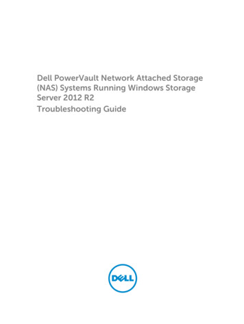
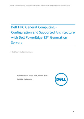
Cabling The Storage ArrayThe iSCSI interface enables different host-to-controller configurations. The figures in this chapter aregrouped according to the following categories: Direct-attached configurations (no Ethernet switches are used) Network-attached (SAN) configurations (Ethernet switches are used) Mixed configurations that uses all protocolsRedundant And Nonredundant ConfigurationsNonredundant configurations are configurations that provide only a single data path from a host to thestorage array. This type of configuration is only recommended for noncritical data storage. Path failurefrom a failed or removed cable, or a failed or removed RAID controller module results in loss of hostaccess to storage on the storage array.Redundancy is established by installing separate data paths between the host and the storage array. Eachdata path is connected to one of the two RAID controller modules installed in the storage array.Redundancy protects the host from losing access to data in the event of path failure, because both RAIDcontroller modules can access all the disks in the storage array.Direct-Attached ConfigurationsYou can connect the Ethernet ports of the host servers directly to the storage array RAID controllermodule iSCSI ports.Single Path Data ConfigurationsWith a single path configuration, a group of heterogeneous hosts can be connected to the storage arraythrough a single physical Ethernet port. Since there is only one port, there is no redundancy, althougheach iSCSI portal supports multiple connections. This configuration is supported for both singlecontroller and dual controller modes.The figure below shows a non-redundant cabling configuration to a RAID controller module using asingle path data configuration12
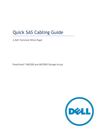
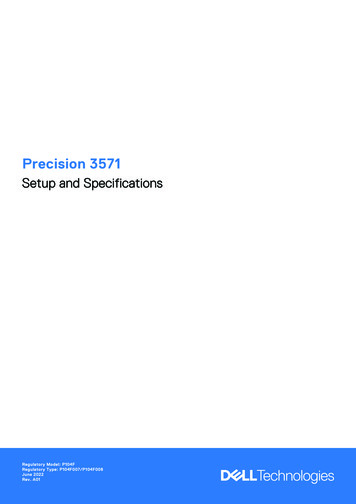
Figure 1. One Host Connected to a Single ControllerThe following figure shows four stand-alone hosts supported in a dual controller array configuration witha single data path.13
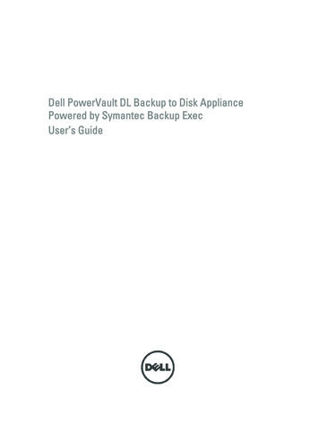
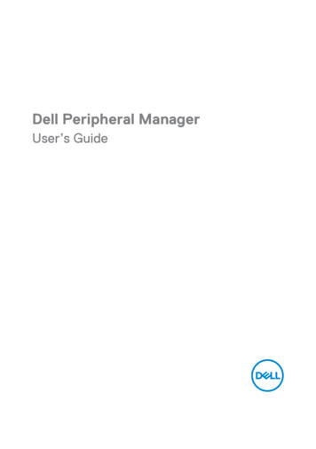
Figure 2. Four Hosts in a Dual-Controller Configuration Using One HBA EachDual Path Data ConfigurationIn the following figure, up to two servers are directly attached to the RAID controller modules. If the hostserver has a second Ethernet connection to the array, it can be attached to the iSCSI ports on the array'ssecond controller. This configuration provides improved availability by allowing two separate physicalpaths for each host, which ensures full redundancy if one of the paths fail.14
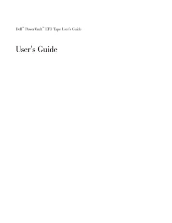
Figure 3. Two Hosts Connected to Two ControllersIn the following figure, up to two cluster nodes are directly attached to two RAID controller modules.Since each cluster node has redundant paths, loss of a single path still allows access to the storage arraythrough the alternate path.15
Figure 4. Two Hosts Connected in a Dual-Controller ConfigurationNetwork-Attached ConfigurationsYou can also cable the host servers to the RAID controller module iSCSI ports through industry-standard10G Ethernet switches. An iSCSI configuration that uses Ethernet switches is frequently referred to as anIP SAN. By using an IP SAN, the PowerVault MD3800i and MD3820i series storage array can support up to64 hosts simultaneously. This configuration supports either single or dual path data configurations andeither single or dual controller modules.The following figure shows up to 64 stand-alone servers attached (using multiple sessions) to a singleRAID controller module through a network. Hosts that have a second Ethernet connection to thenetwork allow two separate physical paths for each host, which ensures full redundancy if one of thepaths fails. It is recommended you use two switches for more redundancy. However, single switchconfiguration is also supported.16
Figure 5. 64 Servers Connected to a Single ControllerThe following figure shows how the same number of hosts can be similarly attached to a dual RAIDcontroller module configuration.17
Figure 6. 64 Servers Connected to Two ControllersThe following figure shows up to 64 stand-alone servers attached (using multiple sessions) to a singleRAID controller module through a network using a 10G aggregation scheme. The NICs on the servers are0 G NICs and the uplink ports are 10G. Hosts that have a second Ethernet connection to the networkallow two separate physical paths for each host, which ensures full redundancy if one of the paths fails. Itis recommended you use two switches for more redundancy. However, single switch configuration isalso supported.18
Figure 7. 64 Servers Connected to a Single RAID ControllerThe following figure shows how the same number of hosts can be similarly attached to a dual RAIDcontroller module configuration. Hardware redundancy is achieved in this configuration, in case of anyswitch failure.19
Figure 8. 64 Servers Connected to Two RAID ControllersMixed EnvironmentThe following figure shows a mixed environment, that is direct attachment using SAS to one hostconnectivity to another host using direct-attached iSCSI or the IP SAN.20
Figure 9. Mixed Environment Cabling for Two ControllersRemote ReplicationRemote Replication is a storage array premium feature that provides online, real-time replication of databetween storage arrays. The diagram below shows an example of how to setup a Remote Replicationenvironment. For more information about Remote Replication, see the MD Administrators Guide atdell.com/support.21
Figure 10. Remote Replication Cabling ExampleCabling PowerVault MD1200 Series Expansion EnclosuresYou can expand the capacity of your PowerVault MD3800i and MD3820i series storage array by addingPowerVault MD1200 series expansion enclosures. You can expand the physical disk pool to a maximumof 120 (or 192, if enabled using Premium Feature activation) physical disks using a maximum of sevenexpansion enclosures.Expanding With Previously Configured PowerVault MD1200 Series ExpansionEnclosuresUse this procedure if your expansion enclosure is directly attached and configured with a Dell PowerEdgeRAID Controller (PERC) H800 adapter. Data from virtual disks created on a PERC H800 adapter cannot bedirectly migrated to a storage array or an expansion enclosure connected to a storage array.22
CAUTION: If a PowerVault MD1200 series expansion enclosure that was previously attached toPERC H800 adapter is used as an expansion enclosure to a PowerVault MD34xx/MD38xx seriesstorage array, the physical disks of the expansion enclosure are reinitialized and data is lost. Youmust back up all data on the expansion enclosure before attempting the expansion.1.Back up all data on the expansion enclosures.2.Upgrade the expansion enclosure firmware to the latest version available at dell.com/support whilethe enclosure is still attached to the PERC H800 controller.Windows systems users can reference the DUP.exe package and Linux kernel users can referencethe DUP.bin package.3.Ensure that the storage array software is installed and up to date before adding the expansionenclosures. For more information, see the Dell PowerVault MD34xx/MD38xx Support Matrix atdell.com/support/manuals.a) Install the software and driver package included on the PowerVault MD series resource media. Forinformation about installing the software, see the topic “Installing PowerVault MD StorageSoftware”.b) Update the storage array RAID controller module firmware and NVSRAM to the latest versionsavailable at dell.com/support.c) Using MDSM, click Tools Upgrade RAID Controller Module Firmware EnterpriseManagement Window (EMW).4.Stop all I/O and turn off the system and attached units.a) Stop all I/O to the storage array and turn off the host systems attached to the storage array.b) Turn off the storage array.c) Turn off the expansion enclosures in the affected system.5.Cable the expansion enclosures to the storage array.a) Connect the MiniSAS HD end of the supported SAS cabled to the SAS OUT Port 0 on the MD1200 series expansion enclosure.b) Connect the other end of the SAS cable to the IN port on the MD 1200 series expansionenclosure.6.Turn on attached units:a) Turn on the expansion enclosures. Wait for the enclosure status LED to light blue.b) Turn on the storage array and wait for the status LED to indicate that the unit is ready:*If the status LEDs are solid amber, the storage array is still coming online.*If the status LEDs are blinking amber, there is an error that can be viewed using the MDSM.* If the status LEDs are solid blue, the storage array is ready.c) After the storage array is online and ready, turn on any attached host systems.7.After the PowerVault MD1200 series expansion enclosure is configured as an expansion enclosure ofthe storage array, restore the data that was backed up in step 1.After the expansion enclosures are online, they can be accessed as a part of the storage array.23
Expanding With New PowerVault MD1200 Series Expansion EnclosuresPerform the following steps to attach new PowerVault MD1200 series expansion enclosures to aPowerVault MD34xx/38xx series storage arrays:1.Before adding the expansion enclosures, ensure that the storage array software is installed and is upto date. For more information, see
Dell PowerVault MD Series Storage Arrays Administrator's Guide — Provides information about configuring and managing the system using the MDSM GUI. Dell PowerVault Modular Disk Storage Arrays CLI Guide — Provides information about configuring and managing the system using the MDSM CLI.