Transcription
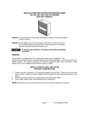
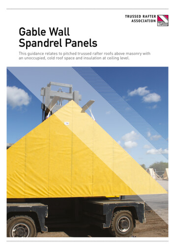
Gable WallSpandrel PanelsThis guidance relates to pitched trussed rafter roofs above masonry withan unoccupied, cold roof space and insulation at ceiling level.
Gable wall spandrel panelsGable wall spandrel panels are an offsite manufactured product. They providean alternative to the inner leaf of an exterior masonry wall at the gable end ofa building. The panels must be designed to comply with structural, thermaland fire resistance (where required) performance standards and current buildingstandards and regulations. As gable wall spandrel panels do not separatehabitable spaces, defined acoustic requirements are not applicable.Please note this document does not cover: Twin wall constructions where bothinner and outer leaves of masonry arereplaced by gable wall panelsThe use of cladding systems otherthan brick.These areas will require separate designand detailing.To assist Building Designers and Contractors, thisdocument sets out some essential guidance onaspects of gable panel design, construction andinstallation for usage above masonry. All images arefor illustrative purposes only. The recommendationscontained within this document are supplied ingood faith but without liability and their use shall beentirely at the risk of the user.Contents01. Design responsibilities0202. Structural considerations0303. Fire resistance0404. Thermal performance0505. Manufacture of panels0606. Site handling details 0707. Installation0808. Gable lateral restraint1109. Staying safe12Images courtesy of Pasquill, Crendon, ITW and Saint-GobainGable wall spandrel panelspage 01
1 Design responsibilitiesGetting the design right on any part of a building is key and for roofing it’sessential that all involved with the design, manufacture and installation of gablewall spandrel panels are working together effectively.Guidance published in PD 6693-1 for theUK and SR 70 for Ireland states: “On everyproject, it is essential that one personassumes overall responsibility as buildingdesigner and is clearly defined as such.”PD.6693-1 then goes on to specificallystate: “The building designer should beresponsible for ensuring the integrationof the design of the various buildingcomponents including the detailing ofsuitable connections between the buildingcomponents and their support structure.The building designer should beresponsible for ensuring adequateprovision is made for the stability of thebuilding, as distinct from, and in additionto, the stability of individual components,including the detailing of all elements ofbracing required in the building.”On each project, there should be a clearunderstanding of who is responsible forthe building design and who is responsiblefor the roof design and/or the elementswithin it, such as trussed rafters, party wallspandrels and gable wall spandrel panels.Information sharing is key to the processand the responsibilities for each designercan be found within Annex A in PD 6693-1and section 10 in SR 70.page 02The building designer should ensure thatthe necessary information is provided toall parties involved in the design of thebuilding.Where specified for supply, gable wallspandrel panels will be engineered bythe manufacturer to meet statedrequirements and withstand the specifieddesign loads provided by the buildingdesigner. These will include wind loads– both pressure and suction – and theacceptable/permitted deflection limit ofthe outer leaf of masonry.As stated above, the building designeris responsible for detailing a suitableconnection between the buildingcomponents (in this case the masonry wallbelow, the wall plate and the gable wallspandrel panel above) and their supportstructure (in this case the restraint of theexternal wall to the roof). Information inthis guide is intended to assist the buildingdesigner in this process and provideguidance on how gable wall spandrelpanels are manufactured, handled andcan be installed.www.tra.org.uk
2 Structural considerationsGable wall spandrel panels must resist wind loads acting on the gable endwalls and any loads imposed by the outer layers of cladding. These loads aretransmitted through the panel to the roof structure via lateral restraints.This guide provides information in relationto single leaf gable wall spandrel panelssupported on the inner leaf of a masonrycavity gable wall. This is a simpleralternative to that defined (as type 5)within the NHBC Technical Guidance7.2/25 on spandrel panels to cold roofs January 2018.Gable wall spandrel panels require robustlateral connections from the gable wallto the roof trusses at rafter and ceilinglevel to effectively transfer loads to themain trussed rafter roof structure. In turn,these loads (tensile and compressive) aretransferred through the top and bottomchords of the trusses to the side walls ofthe building.This transfer of loads is most effectivelyachieved using a structural timber wallplate, which is run continuously aroundthe external walls of the building with thetrussed rafters and the gable wall spandrelpanel fixed at the same level.As an alternative, the structural timberwall plate may be stepped and raised atthe gable end. However, doing sointroduces some complexity to the designand construction process. Lateral loadsshould not be unduly applied to thewebs of trussed rafters, unless specificallydesigned for. For most applications, lateralloads should be applied only to the topand bottom chords.Lateral restraint can be provided by: Metal restraint straps fixed to the paneland to noggings, or timber bracingfixed to the bottom or top chord acrossa minimum of three trussed rafters.Structural calculations should be providedby the building designer to supportthe chosen method of lateral restraint.Restraint strap requirements illustratedin this guidance, either at ceiling level oralong the rafters are to be in accordancewith Approved Document A or equivalent,and BS8103. Examples of lateral restraintwhich are fully supported by suchcalculations are provided in this document(see section 8).Gable wall spandrel panels should beinstalled level with the top of the trussedrafters for fl ush roof verges; or tounderside of gable ladders with boxedverges.Timber frame to masonry wall ties areessential to transfer loads between theouter masonry leaf and the structuralframe of the gable wall spandrel panel.Specifications should be clear whetherprovision of such wall ties form part of thegable wall spandrel panel supply contract.A structural connection is requiredbetween the wall plate and the inner leafof masonry.Trussed rafters not shown to aid illustrationGable wall spandrel panelspage 03
3 Fire resistanceFire protection to gable wall spandrel panels is dependent on the dwelling type,and distance from relevant boundaries. Based on Approved Document B1(England) and 100mm thick masonry outer leaf the fire protection describedbelow would generally apply:The building designer should determinethe fire protection requirements for theproject in association with the appropriateregulatory bodies.Fire protection requirements by dwellingtype are:Three storey houses and two storey flats: Requirement B4 – External spread offire may apply if the building is close toa boundary and the area of the gablewall spandrel panel is larger thanthe allowable ‘unprotected area’ ofthe plot.Where a 30-minute period of fireresistance is needed, an unlined gablewall spandrel panel with 100mm masonryouter leaf is considered to meet thisrequirement.Houses and flats with height exceedingthe above dwelling types: Requirement B4 – External spread offire may apply if the building is close toa boundary and the area of the gablewall spandrel panel is larger than theallowable ‘unprotected area’ of theplot. A 60-minute period of fireresistance is needed. An unlined gablepage 04wall spandrel panel and 100mmmasonry wall is NOT consideredsufficient to meet this period. In thesecircumstances, the building designermust work with the contractor andmanufacturer to determine whatadditional site-applied measures, suchas internal linings to the gable wallspandrel panel, are necessary to achievethe required fire protection.www.tra.org.uk
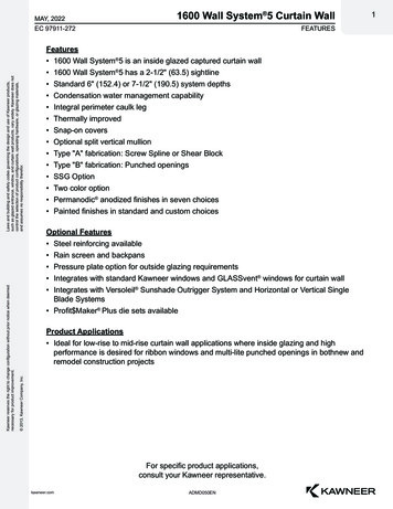
4 Thermal performanceIndicative calculations have been undertaken to demonstrate the performanceof a gable wall and cold roof thermal bridge detail, incorporating a timberspandrel panel, in place of an internal leaf of masonry blockwork. On the basisof the modelling undertaken, all scenarios demonstrate compliance with theminimum surface temperatures/fRsi requirements of BR 497:2016 and theassociated heat loss (y/Psi-value) for use in SAP calculations has beencommunicated.Generic modelling on behalf of TRAdemonstrates that additional cavityinsulation should not be required abovethe trussed rafter wall plate level toachieve the required U-values with timberframe gable wall spandrel panels.Furthermore, indicative calculationssuggest the generic construction detailsin this document can provide thermalperformance comparable with the basicAccredited Construction Details formasonry walls.100mm full fill insulation belowgable detail open cavityGable wall spandrel panelsBuilding designers should ensure thatplot specific thermal bridging and SAPcalculations are undertaken based uponthe exact construction details used.Care should always be taken duringconstruction to minimise the risk ofthermal bridging.100mm full fill insulation belowgable detail closed cavityTo ensure the ceiling maintains aconsistent U-value through to the gablewall, loft insulation shall be laid tightlyabutting the inner face of the sheathingpanel. Unless specified by the buildingdesigner, additional cavity insulation isnot usually required with timber framepanels to achieve the required U-valuesand should be avoided due to the risk ofinterstitial condensation.100mm partial fill insulation belowgable detailpage 05
5 Manufacture of panelsPanels are constructed in the factory using structural timber-framemembers with pressed steel plate or nailed joints. They are clad on one sidewith structural sheathing board, which is covered with a breather membraneto prevent moisture ingress from the cavity during designed service life.Single piece gable panels are recommendedwherever possible, to minimise the needfor working at height on site. Offsitemanufacture shall be subject to thirdparty accredited, quality-assured factoryproduction control.Engineering will be supported by designsoftware and/or structural calculations,including nailed joint specifications, toconfirm the gable wall panel will meetspecified design loads provided by thebuilding designer. Calculations shouldalso ensure that structural integrity ismaintained during handling, delivery,crane offload and site installation.Structural timber-frame members must bea minimum section size of 89 x 38mm or97 x 47mm with nailed connections or72 x 47mm where joints are plated.Vertical studs must be at maximum600mm centres, with horizontal noggingsas required to provide structural integrityand fully support the edges of thesheathing boards. All structural timbermembers must be at a minimum strengthclass of C16 or higher, where required byengineering calculations. If necessary, allstructural timber frame members are to bepreservative treated to Use Class 2 and adesired service life of 60 years.Panels must be clad on one side withstructural sheathing board. This is mostcommonly 9mm-thick OSB Class 3 or 4 tomeet BS EN300, or an alternative asrequired by engineering calculations.Boards must be fixed to the structuraltimber frame using minimum 2.9mm x 50mmnails at 150mm centres on the perimeterof the sheathing sheets and at 300mmvertical spacing elsewhere.page 06The breather membrane specificationmust be in accordance with thebuilding designer’s requirements and inaccordance with NHBC Standards: Clause6.2.13. A membrane must be fixed to theouter surface of the sheathing inaccordance with the manufacturer’srecommendations. An additionalminimum of 200mm of breathermembrane must be provided at the footof the panel. This material must be foldedback and lightly tacked in place to secureit during delivery. At installation, thematerial is released and used inaccordance with accepted details to suitpartial or fully filled cavity insulation. Anillustration is included in this guide. Theposition of studs must be highlighted withtape or marker pen on the outer surfaceof the breather membrane to assist siteinstallation of the wall ties between thetimber frame and masonry wall.Gable wall panels are to be supplied withfactory-fitted, weight-tested lifting strapssuitable for the condition in which thepanels are delivered. The weight of eachpanel must be clearly marked on thepanel itself.www.tra.org.uk
6 Site handling detailsGable panels should be moved usingmechanical handling only.Installers and contractors must providesite-specific risk assessments and methodstatements for the site handling, cranelifting and safe installation of gable wallpanels.Panels should be stored upright only,supported on bearers out of groundcontact and safely restrained to preventinjury.Panels should always be given adequateweather protection on site. Any panel(s)that are unprotected or have sufferedsignificant bowing or wrapping due toexcessive exposure to adverse weathershould not be used/installed in the finalbuild.Further information on the safe unloadingof spandrel and gable wall panels can befound on the TRA website.Gable wall spandrel panelspage 07
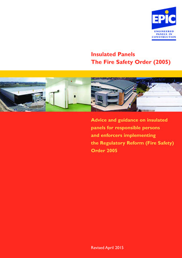
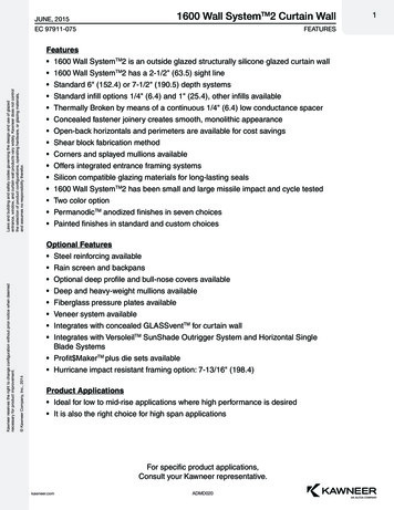
7 InstallationThe installation of gable panels is most easily achieved using a structuraltimber wall plate, which is run continuously around the external walls of thebuilding with the trussed rafters and the gable wall spandrel panel fixed at thesame level. See Figure X below.Single-piece panels are recommendedwherever possible to minimise the needfor working at height on site. Where panelsections are jointed, additional qualitychecks will be needed to ensure thecorrect alignment of the panel sectionsand that fixing is in accordance with themanufacturer’s fixing schedule.Timber frame to masonry wall ties mustbe site-fixed into the structural timberframe members of the gable wall spandrelpanel, in accordance with NHBC StandardsChapter 6.1.18 and Detail 10 of NHBCTechnical Guidance 7.2/25. The positionof studs should be highlighted with tapeor marker pen on the outer surface of thebreather membrane to assist with this siteinstallation.During installation, the lightly fixedbottom edge of the breather membranemust be lifted and positioned to accepteddetail over the cavity insulation. Thisensures that penetrating water in thecavity can be directed away from thebuilding interior, as illustrated in thisguide. Decisions on the use of cavity traysand fire resisting cavity barriers at ceilinglevel rest with the building designer.For the connection between the wallplate and the masonry: Proprietary metalwork connection withproven performance values acceptedby NHBC/TRA must be used The maximum spacing of connectors isdependent on wind loading and sitelocation See section 8 for examples ofconnection details.Figure X: Timber Gable to Masonry fixing detail to cold roofs - continuous wall plate*Gable panelBreather membrane toface of gable panelVertical restraint strapfixed to vertical stud.Refer to manufacturers'details for fixingspecificationInsulation continuedinto gable panel225mm maximum heightbetween underside ofwall plate and horizontalrestraint strapTimber frame wall ties tobe specified by buildingdesignerMortar bedProprietary GableRestraint Bracket with2kN/m minimum designvalueCavity trays and firestopsto be detailed by buildingdesignerCavity insulation shownfor indicative purposesonly - thermal bridgingand SAP calculations tobe plot specificLongitudinal trussbracing225mm MAXContinuous wall plate38mm min-75mmmaximum depthRoof insulationSolid blocking betweentruss and gable panel athorizontal restraint strappositionsGable panel to wall plate fixing timber-to-timber connectioncapable of resisting 2kN/munfactored loadingLevel of truss wall plateHorizontal restraint straps4kN/m minimum declared tensilecapacity fixed to longitudinal trussbracing / additional bracing andgable panel. Please refer tomanufacturer’s details for fixingspecification.Vertical holding down strapsat maximum 1.8m centres.Please refer to manufacturer’sdetails for fixing specificationStraps, brackets and fixings centres to be specified by engineer or refer to product specific detailsStraps, brackets and fixings centres to be specified by building designer or refer to product details*Typical loads shown in the above detail applies only to buildings of up to three storeys in England and Wales, and two storeys in Scotland.page 08www.tra.org.uk
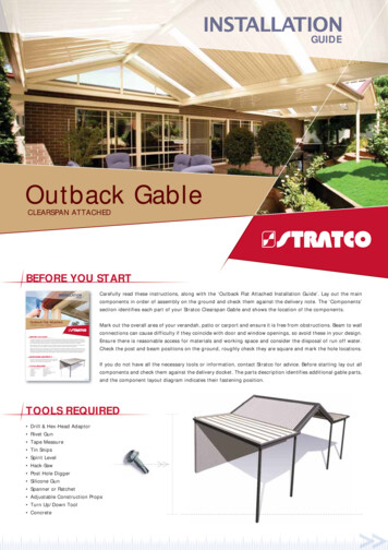
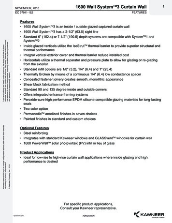
For the connection between the wallplate and gable panel bottom rail: Timber to timber connection capableof resisting appropriate unfactoredloading. See section 8 for examples ofmanufacturers who can provideconnection details.For the restraint at ceiling level: Bracing members to be nominal25 x 100mm with a minimum crosssectional area of 2,134mm2 and aminimum target thickness of 22 mm Longitudinal truss bracing must be laidin line and butted tight against thevertical studs of the gable wall paneland fixed to a minimum of threetrusses using 2no x 3.1mm x 65mm nailsat each truss A horizontal twisted restraint strapmust be fixed to the side of a verticalstud in the gable wall panel and fixedto the longitudinal bracing The maximum spacing of restraintstraps is dependent on the site location.Please refer to manufacturer’s detailsfor fixing specification See section 8 for examples ofconnection details.As an alternative, the structural timberwall plate may be stepped and raised atthe gable end - as illustrated in Figure Y.However, doing so introduces somecomplexity to the construction process.The critical requirement here is that theinner leaf of blockwork needs to beaccurately cut to align with top edge oflongitudinal bracing to prevent the needto bend the angled restraint straps outof level.Finally, typical restraint strap requirementsalong the roof slope at rafter level areillustrated in Figure Z.See section 8 for examples of connectiondetails.Figure Y: Timber Gable to Masonry fixing detail to cold roofs - raised gable wall plate*Cavity trays and firestopsto be detailed by buildingdesignerGable panelBreather membrane toface of gable panelVertical restraint strapfixed to vertical stud.Refer to manufacturer’sdetails for fixingspecificationInsulation continued intogable panelTimber frame wall ties to bespecified by building designerRoof insulationContinuous wall plate38mm min-75mmmaximum depthLongitudinal trussbracing (depth can varyto suit blockwork level)Mortar bedLevels to be adjusted toensure top of bracinginline with top ofblockworkProprietary GableRestraint Bracket with2kN/m minimum designvalueCavity insulation shownfor indicative purposesonly - thermal bridgingand SAP calculations tobe plot specificLevel of truss wallplateSolid blocking betweentruss and gable panel athorizontal restraint strappositionsGable panel to wall plate fixing timber-to-timber connectioncapable of resisting 2kN/munfactored loading90deg bend horizontal restraintstraps 4kN/m minimum declaredtensile capacity. Fixed to longitudinaltruss bracing / additional longitudinalbracing. Please refer to manufacturer’sdetails for fixing specificationVertical holding down strapsat maximum 1.8m centres.Please refer to manufacturer’sdetails for fixing specificationStraps, brackets and fixings centres to be specified by engineer or refer to product specific detailsStraps, brackets and fixings centres to be specified by building designer or refer to product details*Typical loads shown in the above detail applies only to buildings of up to three storeys in England and Wales, and two storeys in Scotland.Gable wall spandrel panelspage 09
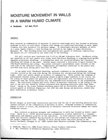
Figure Z: 7 For restraint at rafter level90deg bend Restraint Straps located at, ornear to apex and down the rafters atmaximum 2m centres (no more than 1.25mcentres for buildings over three storeys inEngland or Wales or over two storeys inScotland)Solid timber noggins, minimum 38mm wide, fixed between thefirst three trusses with solid timber blocking between the finaltruss and the gable panel at the strap locations90deg bend Restraint Straps to hook overgable panel and be fixed to outer face ofthe solid timber noggins and trussed rafters.Refer to manufacturer's specification forfixing detailsGable panelBreather membrane to face of gable panelTimber frame wall tiesWhere a gable ladder is used, the 90degbend Restraint Straps hook over a reducedgable panel and are fixed to the inner face ofthe solid timber noggins and trussed rafters,with the gable ladder above. Refer tomanufacturer's specification for fixingdetailsGable panelBreather membrane to face of gable panelTimber frame wall tiesCavity trays and firestops to be detailed bybuilding designerStraps, brackets and fixings centres to be specified by engineer or refer to product detailspage 10www.tra.org.uk
8 Examples of proprietary gable bracket/connector8.1 Cullen gable restraintITW Construction Products’ Cullen brandof timber engineering connectors has beensynonymous with innovation and qualityfor over 40 years. In collaboration withnational housebuilders, the Trussed RafterAssociation and industry partners,its technical experts have created aninnovative system featuring the CullenGable Restraint Bracket for a completesolution to connect timber gables tomasonry walls. The details have beendeveloped to safely transfer lateral windload on the masonry and timber gableends into the braced roof diaphragm. Thisprovides a verified connection betweentimber gable panels to masonry walls.The details give an option to have acontinuous wall plate or a steppedwall plate with the gable wall plate beingraised to suit the bottom chord depth ofthe truss. Either of the details meets theminimum requirement of BuildingRegulations 2010 approved document A,Scottish Building regulations domestic,NHBC Standards for houses of fivestoreys or less – England and Wales andfour storeys or less – Scotland. Both detailsare accepted by NHBC.An NHBC accepted “whole system”solution incorporating the Cullen GableRestraint Bracket and restraint strapsincluding Paslode nail fixings with allcentres, spacings and connections alreadycalculated assures of compliance alongthe value chain. If Cullen’s details are fullyadopted, no further checking is requiredto ensure the safe transfer of lateral windload on the masonry and timber gableends into the braced roof diaphragm.For a Technical Guidance Pack including samples call 01592 777570, option 4 or e-mail cullentechnical@itwcp.com8.2 Simpson Strong-Tie gable panel connectionDO NOT SCALEIF IN DOUBT, ASKSimpson Strong-Tie has developed a rangeof products to provide verifiable connection when connecting timber frame gablepanels to masonry walls and the roofstructure.The Gable Panel Connector (GPC) has beenspecifically developed to connect the wallplate to masonry walls, transferring lateralforces between the two components.The connections have been developed tosafely transfer lateral wind loads imposedon the masonry and timber gable ends intothe braced roof diaphragm, givinginstallation options onto a continuous wallplate or raised wall plate.Either of the installation options meet theminimum requirements of the BuildingRegulations 2010 approved document A,Scottish Building regulations domestic,NHBC standards for house of five storeys,or less in England and Wales, and fourstoreys or less in Scotland.Both the GPC, and the necessary restraintstraps, which complete the system, haveproduct acceptance by the NHBC andprovide the housebuilder with a robustconnection for gable panels. NHBC willrequire specific project design and detailswhen using these products.Material:Steel wire acc. to DIN EN 10016-2Tolerances, unless otherwise statedNo burrs greater than: 0.3mm 1.5mmAll dimensions:90º 1ºAll bends: 1ºAll angles:r 1xt -0/ 0.5tBend radii t 4mm:Bend radii t 4mm:r 1.5xt 0.5tHole dimension 0.2mmFor more details and technical guidance visit www.strongtie.co.uk or call 01827 255600Mechanical:Characteristic tensile capacity f tens,k 600 N/mm²Hardness:Finish:Electroplated.Zink coating A 3K acc. to DIN EN ISO 4042Material:Finish:REVREV DATEREV BYCHKMODEL NO.All dimensions in mmProjectionSCALE1st Angle3rdAngleDATEBYCHKDWG RITTENCONSENT!CONFIDENTIAL: THISTHIS XPRESSWRITTENCONSENT!Gable wall spandrel panelsREV IES.A.S.SIMPSONSTRONG-TIEInt.Inc.TITLES.A.S.Int. edreservedreservedreserved 2014 Simpson Strong-Tie GmbH.page 11
9 Staying safeInstalling trussed rafters and associated gable wall spandrel panelsrequires specific construction skills which involve working at height andhandling dynamically unstable materials.The Construction Design and Management(CDM) Regulations require projects to have: workers with the right skills, knowledge,training and experience, contractors providing appropriatesupervision, instruction and information, a written construction phase plan.Visit the CITB website for more informationon understanding CDM.The installation of roof elements includingtrussed rafters and gable wall spandrelpanels should only be undertaken bysuitably experienced and qualifiedpersonnel, such as those with a Level 2Diploma in Site Carpentry.the principal contractor before any workcommences.A full written site-specific risk assessmentand safe system of work for installationof the trussed rafters and gable panelsshould be developed and approved byMechanical handling equipment such as acrane or a forklift with suitable adaptions isthe preferred method of handling trussedrafters and gable wall spandrel panels.Trussed rafters are to be erected and fullybraced before gable wall spandrel panelsare installed.Safety Checklist: Ensure scaffolding is in place and signed off. A safe working platform within the structure isstrongly recommended. Ensure hop-ups and scaffolding edge protection arein place. Ensure all personal protective equipment (PPE) is wornand correctly fitted. Check and read all assembly drawings and informationprovided by the truss supplier. Always follow the site-specific written constructionphase plan. After reading the truss layout drawings, identify the easieststarting point using the simplest roof of trusses. Consult the site-specific safe system of work before anyroof work commences. Once the trussed rafters are erected and their permanentbracing is completely and fully fixed then the gable wallspandrel panels can be installed. Gable wall spandrel panels should be permanentlyrestrained as soon as they are installed. Unrestrained panelswill pose an immediate risk to site workers and others.All images in this guide are for illustrative purposes only. The recommendations given are supplied ingood faith but without liability. Their use shall be entirely at the risk of the user.page 12www.tra.org.uk
Visit our website for more information: tra.org.uk or traireland.ieThe Building Centre26 Store StreetLondonWC1E 7BTT: 020 3205 0032E: info@tra.org.ukThe latest version of this guide can be downloaded online at tra.org.uk or traireland.ieAll information is correct at the date this guide was produced. We reserve the right to make technical changes at any time.Gab0001 – 2020/01
aspects of gable panel design, construction and installation for usage above masonry. All images are for illustrative purposes only. The recommendations contained within this document are supplied in good faith but without liability and their use shall be entirely at the risk of the user. Gable wall spandrel panels are an offsite manufactured .