Transcription
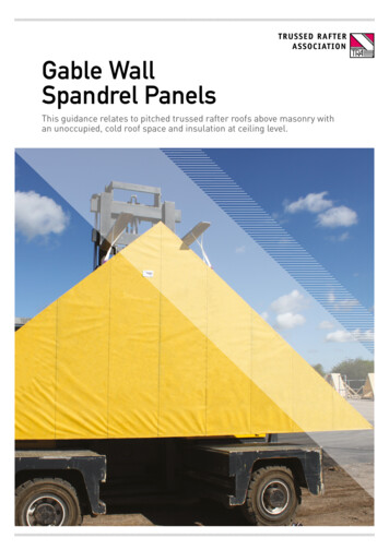
GUIDEOutback GableCLEARSPAN ATTACHEDBEFORE YOU STARTINSTALLAINSTALLAATITIONONCarefully read these instructions, along with the ‘Outback Flat Attached Installation Guide’. Lay out the mainGUIDGUIDEcomponents in order of assembly on the ground and check them against the delivery note. The ‘Components’section identifies each part of your Stratco Clearspan Gable and shows the location of the components.Outback Flat Attached Mark out the overall area of your verandah, patio or carport and ensure it is free from obstructions. Beam to wallVERANDAHS PATIOS CARPORTSconnections can cause difficulty if they coincide with door and window openings, so avoid these in your design.BEFORE YOU STARTIt is important to check your Local Government Authority requirements before the installation of your new Stratco Outbackk Flat Verandah. It is the builderʼs responsibility to ensure any existing structure that an Outback Flat is being attached to is adequately reinforced to accommodatethe additional loads imposed by the verandah, patio or carport. Read these instructions thoroughly before starting your project and refer tothem constantly during each stage of construction. Contact Stratco for advice if you do not have the necessary tools or information.Ensure there is reasonable access for materials and working space and consider the disposal of run off water.Before starting, lay out the main components in order of assembly on the ground and check them against the delivery note. The ʻComponentsʼsection identifies each part of your Outback Flat Verandah or Carport and shows the relative location of the components.Mark out the overall area of your verandah, patio or carport and ensure that it is free from obstructions. Beam to wall connections can causedifficulty if they coincide with door and window openings, so avoid these in your design. Ensure there is reasonable access for materials andworking space and consider the disposal of run-off water. Check the column and beam positions on the ground; roughly check they are squareCheck the post and beam positions on the ground, roughly check they are square and mark the hole locations.by measuring the diagonals, then mark out the column locations. If columns are to be ʻin groundʼ, dig the holes to Stratco specifications.ADDITIONAL MATERIALSThe Outback kit does not include fixings to attach the unit to an existingstructure or concrete/masonry anchors for the column installation. Ifrequired, they must be purchased as additional items.TOOLS REQUIRED Drill & Hex/Phillips HeadAdaptorsIf you do not have all the necessary tools or information, contact Stratco for advice. Before starting lay out all Post Hole Digger Silicone Gun Rivet Gun Spanner or Ratchet Tape Measure Adjustable Construction Props Tin Snips Turn Up/Down Tool Spirit Level Concrete Hack-Saw Laddercomponents and check them against the delivery docket. The parts description identifies additional gable parts,and the component layout diagram indicates their fastening position.TOOLS REQUIRED Drill & Hex-Head Adaptor Rivet Gun Tape Measure Tin Snips Spirit Level Hack-Saw Post Hole Digger Silicone Gun Spanner or Ratchet Adjustable Construction Props Turn Up/Down Tool Concrete
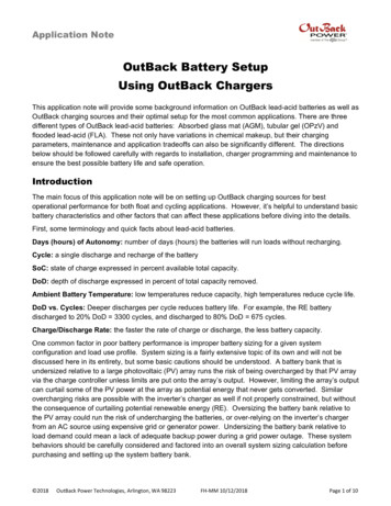
COMPONENTSRIDGE KNUCKLERAFTERSRAFTER TO VALLEY BRACKETSPACERSSlots inside the gable rafters to formconnection at the ridge.Gable Rafters consist of pre-cut 120Outback beam.This bracket fastens the rafter to thevalley beam.Used to prevent the 150 attachmentbeam from crushingSOAKER FLASHINGBEAM CAPPINGEND STRUT22 OR 30 END STRUT PLATEWater proofs the rear of the gable andconceals the existing house gutter.Fixed to top of the valley beam toprovide support for outback deck.Consists of a section of post.Supports the gable in-fill.Secures the end strut at the ridge.14 x 9512 x 20Rivet10 x 16HEADER BEAM BRACKETRIDGE CAPBARGE CAPSCREWS AND RIVETSConnects end strut to header beam onan in-fill gable.This flashing covers the roof sheets atthe gable ridge.The barge cap covers the area wherethe deck finishes at portal frame.Vary depending upon the connection,ensure correct fixings are used.BOLTSGABLE BEAM BRACKETRIDGE RAFTER BRACKETBEAM TO BEAM BRACKETVary depending upon the connection,ensure correct fixings are used.Connects rafters to header beamon an infill gableConnects ridge beamto rafters on a gable.Connects horizontal beams.M10 Hex HeadM12 Hex HeadCupheadBEAM FILLERHEADER FLASHINGSPOST BRACKETPOST CAPFills gap between intersecting Beams.Run along header beam to neatlyfinish the base of in-fill panels.Connects post to beam.Fills gap between post and beam.PANEL STRIPSIN-FILL PANELFINIALDecorative strips fixed toin-fill panels.Cut to suit gable end frames.Provides decoration at the apex ofthe gable end frame.
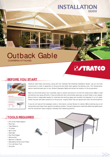
ADDITIONAL MATERIALSPlease note that the Stratco Outback kit does not include any brackets or fixings to attach the unit to the existing structure, or concrete/masonry anchors for column installation. Other items not included in the standard kit are infill panels and accessories, finials, box gutters,cover flashings and concrete.COMPONENT LAYOUT1842531861716912715131110141Ridge Capping6Gable Rafter11Header Beam16Header Beam Bracket2Flat Section7Valley Beam12Barge Cap17End Strut3Outback Deck8Angle Back Channel13Post Bracket18End Strut Plate4Ridge Beam9Beam Capping14Post5Ridge KnuckleGable Beam Bracket15Gutter10
INTRODUCTIONPlease read these assembly instructions thoroughly before commencing the construction. Double check all dimensions, levels and boltinglocations before cutting, screwing or bolting structural members. It is recommended that the persons erecting the structure have had someprevious building experience because some modifications to the existing house structure are required.ATTACHING TO AN EXISTING STRUCTUREThe builder is to ensure the existing house/structure is of a suitableRafter Strengtheningstructural integrity and complies with all the relevant AustralianThe first step is to determine the number of rafters which need toBuilding codes and standards. For more information regardingbe strengthened and their location relative to the unit. You will havethe suitability of the house structure to accommodate the Stratcoto lift some roof tiles or roof sheets to discover the rafter positionsAttached Clearspan Gable, consult a structural engineer or a buildingand spacings. The number of rafters which need to be strengthenedauthority. It is the builder’s responsibility to ensure that the existingis determined by the builder, however spacing is recommended nothouse roof structure is strengthened correctly.to exceed 1200mm.Refer to section 2.1 if attaching Clearspan Gable on its side to aNote: It is the builder’s responsibility to ensure the existinghouse, section 2.2 if attaching on its end to a house or refer to bothrafters and fascia are adequately reinforced and strengthened tosections if attaching the gable on its side and end.accommodate any additional attached structure. The reinforcingmethod must be approved by the appropriate council or engineer.Attaching On Side To HouseIt is recommended an adjustable rafter strengthening bracket is usedA Stratco Clearspan attached on its side to a house is attached toin conjunction with an extension channel, as shown in (Figure 3).the existing eaves overhang at the fascia, or to an existing wall ifThe adjustable rafter strengthening bracket is shown in (Figure 2).height permits.Please note that this bracket may not be suitable for applicationsThe first objective in the construction is to fix a structural side beamwhere the front face of the house gutter is higher than 120 mm. Inalong the fascia or wall, to which the Gable Unit is attached.these cases please contact Stratco for alternative solutions.Most existing houses have not been designed for the attachment ofThe adjustable rafter strengthening bracket allows for an adjustmentportal framed gables to their side, therefore additional strengtheningof pitch in the range of 15 to 30 degrees. The distance the bracketof the house rafters must be performed.extends past the fascia is also adjustable to allow for standard guttersIn order to strengthen the existing house rafters, the roof tiles or(minimum extension) or box gutters with a width of up to 200mm.roof sheets need to be lifted to expose the roof frame. Steel rafterIn conjunction with rafter strengthening brackets a channel isbrackets and channels are then bolted along the house rafters. Referfixed to the side of the house rafter (Figure 3). The bottom end ofto section 2.1.1.the channel will be located at the base of the house rafter. HolesA 150mm Outback beam is bolted to the strengthening brackets atthe fascia. Once the 150 attachment beam is secured to the house,the Gable Unit can be erected and fastened to the beam.should be marked and pre-drilled in the channel to suit the locationof existing holes in the bracket. The channel will extend beyondthe bracket so additional holes are to be drilled in the channel atapproximately 500mm centres.60 x 44 x 2.0 G450Galvanised ChannelRafterStrengtheningBracketM12 BoltAdjustable RafterStrengthening BracketTimber RafterFigure 2Figure 3
Enough Clearance For Roof SheetsTo Run Into House GutterOutback Roof SheetT PieceBracket ArmTighten To35Nm TorqueM12 WasherRafterM12 Spring Washer105 AttachmentRafter StrengtheningBeamBracketFix Bracket As Close As PossibleTo The Base Of The GutterM12 NutFigure 5M12 x 40Cup Head BoltThe 150 attachment beam is fixed to the end plate to ensure thecarport roof sheets drain into the existing house gutter (Figure 5).Figure 4Initially the bracket T piece shall be fixed to the bracket arm withAfter fixing all the brackets and channels, the 150 attachment beamis fixed in place.two M12 cup head bolts (hand tighten only), a spring washer is to beProp up the 150 attachment beam in position with the double flangelocated between the standard M12 washer and nut (Figure 4). Markon top, the beam will need to be located at a height on the bracketthe position of the bracket on the fascia and notch a rectangularwhich allows clearance between the gable roof sheets and the gutter.hole in the fascia allowing the bracket to be fed through the frontFix to the end plates of the rafter bracket using two M12 bolts, withthe bolt head on the 150 attachment beam side. Insert spacers toof the fascia.The hole may need to be enlarged slightly if the M12 cup headbolts interfere with the fascia. Insert the bracket through the fasciaprevent the beam from crushing, and bolt in position, using nutsand washers.and fix with the channel to the house rafter using M12 hex headThe 150 attachment beam becomes the base for the attachment ofbolts through the existing holes in the bracket and further up thethe Clearspan Gable unit. (Figure 6) shows a unit attached at the side.channel (Figure 6). Adjust the T piece so it is horizontal and hasthe appropriate extension past the fascia to allow for fixing of theattachment beam. T piece connection bolts are to be tightened to aminimum 50Nm torque.Fix the bracket as close to the base of the gutter as possible(recommended minimum distance 10mm from lowest end of gutter),as shown in (Figure 50).Note: Do not over tighten bolts as this can lead to a visibleindentation due to the high gloss nature of the material. Refer to(Figure 7) for fixing spacers.To insert spacers drill 13mm holes through the 150 attachmentbeam. Then drill 16mm holes on the outside face only, ie, this timedo not drill all the way through. This will allow the spacer to slide infrom the outside and stop at the other side as shown in (Figure 7).A cover flashing may be ordered as an additional option and customAmade to cover the exposed brackets and holes through fascia. RivetRefer Figure 4WebOverhanflashings in place, (Figure 8) suggests a simplified flashing.gAChannelTimber RafterExtensionRafter Strengthening BracketAttached To Rafter With 6 x M12Hex Head BoltsRecommended Channel ExtensionBeyond Birds Mouth: 1900mmRecommended Web Overhang: 400mm150 Attachment Beam Fixed ToRafter Bracket With Two M12 BoltsChannelGutterBirds MouthRafterStud WallEaves OverhangBrick Work150 Attachment BeamFigure 6
rafters (Figure 9). Brackets and reinforcement channels are alsoBeam Cappingrecommended to the first rafter either side of the valley beams.Beam Channelthrough pre-drilled holes and bolt through backchannel and fasciaSecure brackets to rafters with 12x25mm timber fixing screws150 AttachmentBeamwith M10 bolts.Double FlangeNote: It is the builder’s responsibility to ensure the existing raftersRafterStrengtheningBracketand fascia are adequately reinforced and tied down to accommodateSpacerM12 Boltany additional attached structure loads.WasherNutBeam Capping13mm HoleEnlarge Hole(16mm This Side Only)HouseGutterFigure 7150AttachmentBeam2.2 Attaching On End To HouseIf fixing a Clearspan Gable on its end to a wall, two alternativesare available. Ridge and valley beams are fixed directly to the wallusing beam to wall brackets. This option will not require a reargable frame and back channel is fixed to the wall to accommodateRivetsheets running along the wall. The other alternative requires valleyRivetFasciaStrengtheningBracketCover Flashing(Optional)beams be fixed to the wall and a rear gable frame installed. The rearFigure 8gable frame will need to be slightly offset from the wall to allow theappropriate bracket fixing.If fixing a Clearspan Gable on its end with suspension brackets to afascia (Figure 9) typically a soaker flashing is used. In this case theExtended Facia Strengthening Bracket( Attached To Rafter & Back Channel)120 Gable Raftergable rafter at the rear of the unit is to be set back sufficiently fromthe house fascia to accommodate the house gutter and infill panelIn-Fill Panel(refer to Figures 22 and 23).GutterSoakerFlashingBeamCappingIf fixing a Clearspan Gable on its end to an attachment beam,elevated to the existing house gutter height, the attachment beamis to be as close as possible (within 5mm) to the outside face ofthe gutter (Figure 24). The 150 attachment beam is fixed to rafterSoffit LiningBack Channelstrengthening brackets as detailed in section 2.1.1.Suspension BracketValley Beam2.2.1 Fascia StrengtheningIt is recommended extended fascia strengthening brackets arefastened at a spacing not exceeding 1200mm centres to fascia andFigure 93.0 GABLE FRAME ASSEMBLYIMPORTANT: Ensure that the double thickness portion is at the topwhen installing all beams and rafters.Note: The rafters are supplied pre-cut and drilled at the ridge asshown in (Figure 10). Insert ridge knuckle into the pre-cut raftersand screw together using two 12x20 hex head self drilling screwsthrough both sides of each rafter and two 12x20 hex head selfdrilling screws through the top (double flange side) of each rafter.Open Gable RafterIn-Fill Gable RafterFigure 10
Pilot holes indicate screw locations as shown in (Figure 11). MakeMeasure the distance between rafter ends, (O), to check valley beamsure that the two ends are flush at the connection, leaving no gaps.spacing (Figure 12).Gable Opening (O)Figure 12Collar Tie Length(L 3000)Figure 113.1 Collar TiesIf collar ties are required on intermediate frames they are to bemitred to suit the pitch of the gable rafters. For gable openings upFix Bracket To RafterUsing Four 12 x x20Hex Head Screwsto 6000mm collar ties are to be located mid-height of the gableframe. For gable openings greater than 6000mm collar ties are to belocated at a height to give a collar tie length of 3000mm.Collar tie brackets are to be fixed to gable rafters with four 12x20hex head self drilling screws at the appropriate height. Collar tiesFix Collar Tie Using Two12 x x20 Hex Head ScrewsEach Sideare then fixed inside the brackets using two 12x20 hex head selfdrilling screws either side (Figure 13).Figure 134.0 VALLEY BEAM ASSEMBLYBefore erecting the valley beams fix capping to the top of the beams.4.1 Side AttachedFirst fix beam channel to the top of the valley beam using 12x20For side attached units fix the rafter to valley brackets to the beamhex head self drilling screws at maximum 500mm centres as showncapping (150 attachment beam will be considered a valley beam)in (Figure 14). Fix the beam capping to the channel using 3mmat the correct rafter positions (refer Section 5) using six 12x20mmrivets each side at maximum 500mm centres, ensuring the break ishex head screws per bracket through the pre-drilled holes (Figurelocated in the top groove (Figure 14).15). Please note that the bottom face of the bracket is in line withIf attaching the valley beam to a header beam, notch the capping sothat it sits on top of the beam as shown in (Figure 21).the bottom edge of the upper groove in the beam. Check positionsbefore drilling.If any intermediate columns are required measure the valley beammarking where they meet. Fasten post brackets as explained inBeam Capping‘Outback Flat Attached Verandahs, Patios & Carports’ under “BracketBeam ChannelFix Beam Capping ToChannel Using 3mmRivets Each Side At500mm CentreLocate The Break OnThe Top Groove OfValley Beamand Filler Connections”. Support the second valley beam at thespacing determined in Section 3.0 on adjustable construction props.4.2 End AttachedFor units attached on the end to a wall, wall brackets are positionedat either side of the gable opening at the spacing determined insection 3.0. The first bracket is fastened to the wall with two M8Valley BeamFix Beam ChannelTo Top Of The ValleyBeam Using 12 x 20Hex Head Self DrillingScrews At 500mmCentresmasonry anchors. The curved legs of the bracket are located at thetop (Figure 16).Do not anchor to mortar joints. Locate the first valley beam (beamcap on top) up into the wall bracket so the curved legs locate againstFigure 14the top flute of the beam.
Beam Capping40150 Valley Beam203025252525Bracket Position InlineWith The Bottom EdgeOf The Upper GrooveBracket Position InlineWith The Bottom EdgeOf The Upper Groove120 VALLEY BEAM WITH22 RAFTER TO VALLEY BRACKET150 VALLEY BEAM WITH22 RAFTER TO VALLEY BRACKET303025252525Bracket Position InlineWith The Bottom EdgeOf The Upper GrooveBracket Position InlineWith The Bottom EdgeOf The Upper Groove150 VALLEY BEAM WITH120 VALLEY BEAM WITH30 RAFTER TO VALLEY BRACKET30 RAFTER TO VALLEY BRACKETFigure 15The valley beam is fastened to the wall bracket with 10x16 hex headWall Bracketscrews in the pre-drilled holes while the opposite end is supportedon adjustable construction props.For units attached on the end to a fascia, suspension brackets15are positioned at either side of the gable opening at the spacingdetermined in Section 3.0 (Figure 12). The top tab of the suspensionbracket must be located between the fascia and back channel.A minimum of two M6 bolts with washers are fixed through backchannel, suspension bracket and fascia (Figure 17).If back channel is not present, (ie, no adjacent flat roof) locate aTwo M8 Masonry Anchors With MinimumEmbedment of 65mmorTwo 8mm Diameter Screwbolts With aMinimum Embedment of 65mm2mm washer plate behind fascia at suspension bracket. Fix throughbracket, fascia and plate.The first valley beam is fastened into the suspension bracket withMinimum Edge Distance of Bolts andScrews is 10 x dia10x16 hex head screws through the dimples while the opposite endFigure 16is supported on adjustable construction props.
For units attached on the end to an attachment beam (Figure 24),In-Fill Panelbeam to beam brackets are positioned at either side of the gable120 Gable RafterFaciaopening at the spacing determined in Section 3.0 (Figure 12).GutterSoakerFlashingFix beam to beam brackets to the attachment beam (header beam)with two 10x16 hex head screws so they clamp the beam filler toBack Channelthe beam (Figure 18).The first valley beam is fastened over the beam to beam bracket withtwo 10x16 hex head screws either side while the opposite end issupported on adjustable construction props.If any intermediate columns are required measure the valley beamM6 Boltsand Washers1 mm SteppedBack ChannelBeam CappingSuspension Bracketmarking where they meet. Fasten post brackets as explained in theFigure 17Stratco Installation Guide ‘Outback Flat Attached Verandah, Patios &Carports’ under “Bracket and Filler Connections”. This can be doneTwo 10 x 16 Hex HeadSelf Drilling Screwsbefore valley beams are fixed in place.Support the second valley beam on adjustable construction propsbut do not fix to the wall, fascia or attachment beam until the frontValley BeamBeam To Beam BracketAttachment(Header) Beamgable frame has been attached.Fix the rafter to valley brackets to the beam capping at the correctrafter positions (refer Section 5). Fixing details as indicated inSection 4.1.Beam FillerTwo 10 x 16 Hex Head SelfDrilling Screws Either SideFigure 185.0 GABLE FRAME CONNECTION5.2 Gable Frame With Infill5.1 Gable FramesThe rafter to valley brackets are attached to the beam cappingusing six 12x20 hex head screws (Figure 15, Section 4.1) at the5.2.1 Front InfillWhere there is an infill at the front of the unit (and/or rear, in theappropriate locations.case of side attached), run the front fascia beam of the flat roofFix the gable rafters into the rafter to valley brackets with two 12x20hex head screws either side (Figure 19).section (if applicable) continuously across the opening to supportthe infill panel and form a header beam (the gutter subsequentlyIf attached on the end, attach the second valley beam into the wallor suspension bracket.runs full length of the header beam). Measure the end gable frameopening and attach gable beam brackets to the header beam at theappropriate spacing using a minimum of four 10x16 hex head selfIntermediate frames should be spaced evenly and fixed into rafter tovalley brackets as previously described.drilling screws.Rafters are supplied notched at the base to fit the gable beamA rear gable frame without a header beam is fixed as per anbrackets. Rafters are fastened inside the gable beam brackets withintermediate frame.a minimum of three 10x16 hex head self drilling screws either sideas shown in (Figures 20 or 21).Valley Beam Capping5.2.2 Rear InfillR120A rear header beam will be required if the unit includes infill to therafterear gable frame. For units attached at the rear with suspensionbrackets, the rear header is fixed between valley beams using beamto beam brackets. If fixed at the rear to an attachment beam (FigureRafter To Valley Bracket24), the attachment beam becomes the header (valley Rafters aresupplied notched at the base to fit the gable beam brackets. Raftersare fastened inside the gable beam brackets with a minimum ofValley BeamTwo 12 x 20 Hex HeadScrews Either SideFigure 19three 10x16 hex head self drilling screws either side as shown in(Figures 20 or 21).
Attach Rafter To Bracket Usinga Minimum of Three 10 x 16Hex Head Self Drilling ScrewsEach SideNote:1.the required dimensions. The rafter setback will need to beadjusted to suit.Gable Beam Bracket2.Header BeamA custom made soaker flashing will need to be ordered toDo not form stop ends at either end of the soaker flashing.3. Soaker flashing is not to come in contact with the base of thehouse gutter.Attach Gable Beam BracketUsing a Minimum of Four10 x 16 Hex Head Self Drilling ScrewsValleyBeamSoakerFlashingFigure 20Attach Rafter To Bracket Usinga Minimum of Three 10 x 16Hex Head Self Drilling ScrewsEach SideRafterBeam CappingFigure 22Header BeamSteel Facia Bracket( Attached To Rafter & Back Channel)ValleyBeam120 Gable RafterSplit Tail Soft Pull RivetsGable Beam BracketIn-Fill PanelGutterAttach Gable Beam BracketUsing a Minimum of Four10 x 16 Hex Head Self Drilling ScrewsFigure 21Back ChannelSuspension BracketRafterSetback5.2.2.1 Soaker FlashingIn the case of a rear infill panel, a soaker flashing is used to concealthe existing house gutter, waterproof the rear end of the gable andneatly finish the base of the in-fill panel (Figure 22).BeamCapping20mm GapSoffit LiningNotch Beam CappingTo Fit Over BeamSoakerFlashingValley BeamFigure 235.2.2.2 Header FlashingWhen a gable is fixed at the rear to an attachment beam, elevated toThe rear gable frame and header beam are set back in order tothe existing house gutter height, typically a header flashing is usedaccommodate the standard soaker flashing which is optional within conjunction with the rear infill. In this case, the rear attachmentthe Outback unit (Figure 23). The frame is fixed on the rear headerbeam is considered a header and along with the rear gable framebeam into gable beam brackets as previously detailed.is fixed as close as possible (within 5mm) to the existing gutter inFix the standard soaker flashing into position on top of the backchannel and underneath the gutter. Infill panels must be fixed withorder to accommodate the header flashing. The gable frame is fixedon the rear header to gable beam brackets as previously described.split tail soft pull rivets at 500mm centres a minimum of 20 mmFix the header flashing into position over the existing gutter lip withabove the pan of the soaker flashing.rivets. Infill panels are located behind the header flashing and fixedThis will reduce the possibility of moisture being absorbed into thesheet. See Section 14 for details of fixing infill panels to gable frames.with split tail soft pull rivets at 500mm centres (Figure 24).Refer Section 14 for details of fixing infill panels to gable frames.
Infill PanelHeader FlashingBeam CappingSplit TailSoft Pull RivetHouse GutterValley Beam150 AttachmentBeamStrengtheningBracketFasciaFigure 246.0 RIDGE BEAM6.1 Assembling Ridge BeamAssemble ridge beam before attaching to gable frames. Fix angledOverhanging 150Ridge Beamback channel to both sides of the ridge beam using 10x16 hex headself drilling screws at 500mm centres, ensuring that the top of theOverhang Back ChannelFlush With End of Beamback channel is in line with the bottom of the beam chamfer asshown in (Figure 25). The back channel should run 34mm past theend of the beam at both ends of the ridge beam. If there is no rearportal frame, finish the back channel flush at one end.Fasten 10x16 hex head self drilling screws at 500mm centres alongthe double flange of the ridge beam (Figure 25).In the case of decking overhanging the gable frame, run the angledback channel to the end of the overhanging ridge beam as shown in(Figure 26). A ridge rafter bracket will be required on both sides ofthe ridge to support overhang.Attach Angled Back Channel To RidgeBeam Using 10 x 16 Hex Head SelfDrilling Screws at 500mm Centres6.1 Attaching Ridge BeamFigure 26Fix the ridge rafter bracket at the ridge with six 12x20 hex head selfdrilling screws through the gable frame and into the ridge knuckle.Position the ridge beam so that the angled back channel rests onSix 12 x 20 Hex Head SelfRidge Rafter BracketDrilling Screwsthe gable frame (Figure 27). Fix the ridge rafter bracket using two12x20 hex head self drilling screws each side (top screw may befastened through the backchannel into the bracket & beam).150 Ridge BeamAttach Using 10 x 16 Hex Head SelfDrilling Screws at 500mm Centres AlongDoublle Flange of Ridge BeamAngled Back ChannelAttach Angled Back Channel To ridgeBeam Using 10 x 16 Hex Head SelfDrilling Screws at 500mm CentresTwo 12 x 20 Hex Head SelfDrilling Screws on Each SideOverhang Back ChannelFigure 25Figure 27
7.0 REMAINING ASSEMBLYAssemble the remaining framework of the flat verandah (if applicable) as per the installation guide; ‘Outback Flat Attached Verandah, PatiosAnd Carports’.8.0 COLUMNS AND FOOTINGSIf fixing the columns into the ground, dig the holes to the specifiedsize. Place a full or half brick in the bottom of the hole as shown in(Figure 29).Post CapBeamBracketMeasure from the underside of the beam to the top of the brick andcut posts to this length at each post location.Post Bracket8.1 68 Outback ColumnIf 50x50 mm square hollow sections (SHS) have been supplied, thefluted 68 Outback columns will need to be reinforced.Cut the 50mm SHS 75mm shorter than the fluted post and slide intothe column.NotchedBeam Filler10 x 30mm Counter SunkSelf Drilling ScrewsTwo 12 x 20mm Hex HeadScrews Through Both SidesOf The Column10 x 16 SelfDrilling Screws7525min 100Ensure the square section is positioned inside the column and fixusing two 12x20 hex head screws per side, at both ends, as detailedTwo 12 x 20mm Hex HeadScrews Through Both SidesOf The Columnin figure 28 and 29.Regardless of whether the column is reinforced, slide the top of theSHS ColumnReinforcement(Not Always Required)68 Outback column over the installed post bracket until it is flushwith the underside of the fascia beam.The unfluted faces of the column should be aligned with each faceof the post to beam bracket.Fasten the 68 Outback column to the post bracket using two 12x20hex head screws either side as shown in (Figure 29).Two 12 x 20mm Hex HeadScrews Through Both SidesOf The ColumnUse construction props or bracing to hold columns in position, butdo not concrete in place at this stage.Width As50 x 50 x 3.0mm8068 Outback ColumnB30mmDepth As68mmSection B - BCorbelB68mm50 x 50mmSHS ColumnReinforcementBrickColumn EmbeddedMinimum 300mm IntoFootingFigure 28Figure 29
9.0 FOOTING PLATESFooting brackets are available when fixing posts to an existingthe post to beam bracket. Fasten using two 12x20 hex head screwsconcrete slab.either side as shown in (Figure 29).Establish the column lengths by measuring the distance from theUse construction props or bracing to hold columns in position butunderside of the fascia beam to the concrete slab, less the thicknessdo not bolt to the concrete slab at this stage.of the footing plate (or 20mm for Outback footing plate).9.2 SHS Reinforced Column Footing Plate9.1 68 Outback Column Footing PlateSlide the SHS reinforced footing bracket into the bottom of theFor non-reinforced 68 Outback posts, cut the columns to length,column, pre-drill a
Attached Clearspan Gable, consult a structural engineer or a building authority. It is the builder's responsibility to ensure that the existing house roof structure is strengthened correctly. Refer to section 2.1 if attaching Clearspan Gable on its side to a house, section 2.2 if attaching on its end to a house or refer to both