Transcription
Nissan 350Z (VQ35DE)Installation Manual
Product Warranty StatementLINK ENGINE MANAGEMENT LTD – LIMITED LIFETIME WARRANTYAll Engine Control Units (ECUs) manufactured or distributed by Link Engine Management Ltd are subjectto the following LIMITED LIFETIME WARRANTIES, and no others.Link Engine Management Ltd warrants only to the original purchaser of the ECU, for the lifetime of theECU, (subject to the limitations set out below), that the ECU shall be free from defects of materials andworkmanship in the manufacturing process. This warranty ceases to apply and does not apply to ECUs thathave not been manufactured or distributed by Link Engine Management Ltd for a period of greater thanone year.An ECU claimed to be defective must be returned to the place of purchase. Link Engine Management Ltd,at its sole option, may replace the defective ECU with a comparable new ECU or repair the defective ECU.This limited lifetime warranty is not transferable and does not apply to any ECU not properly installed orproperly used by the purchaser or end user, or to any ECU damaged or impaired by external forces. Theabove warranties are the full extent of the warranties available on the ECU. Link Engine Management Ltdhas no liability to the original purchaser or any other person for any loss, injury or damage to persons orproperty resulting from the use of the ECU or any failure of or defect in the ECU whether by general,special, direct, indirect, incidental, consequential, exemplary, punitive, or any other damages of any kind ornature whatsoever. Link Engine Management Ltd specifically disclaims and disavows all other warranties,express or implied, including, without limitation, all warranties of fitness for a particular purpose, warrantiesof description, warranties of merchantability, trade usage or warranties of trade usage.For off-road use only, not intended for highway vehicles. This ECU contains a user-configurable softwareprogramme, which is updated by Link Engine Management Ltd from time to time. The user must ensure thecurrent correct version of this programme is downloaded from the website of Link Engine Management Ltdand installed in the ECU prior to use. This limited lifetime warranty does not apply where the ECU hasbeen installed with the incorrect version of the software programme. The user is solely responsible for thesetup and testing of all user-configurable features.Link Engine Management Ltd License AgreementThe software programme in this ECU is licensed not sold. Link Engine Management Ltd grants the user alicense for the programme only in the country where the programme was acquired. No other rights aregranted under this license and the programme may only be used on one machine at a time. If theprogramme is transferred a copy of this license and all other documentation must be transferred at thesame time. The license may be terminated by the user at any time. Link Engine Management Ltd mayterminate the licence if the user fails to comply with the terms and conditions of this license. In either eventthe copy of the programme must be destroyed.
Contents3Table of ContentsPart I Introduction51 Safety .Notice52 Disclaimer. 53 Support.Options5Part II Pre-Installation61 Compatibility.Check6350ZLinkFZJ100Link. 6. 62 Injector.Impedance6350ZLink. 67Part III Installation1 ECU Handling.Procedures72 Fitting.the ECU7350ZLink. 7Part IV Additional Sensors101 MAP .Sensor10350ZLink. 102 IAT Sensor. 10350ZLink. 103 Expansion.Connector10350ZLink. 11Part V PC Tuning121 Installing.PCLink122 Communicating.With Your ECU12Part VI Pre-Start Configuration131 Firmware.Version132 Base Configuration. 133 MAP .Sensor Calibration134 TPS Calibration. 135 IAT Sensor.Selection146 Input .and Output Setup147 Trigger.Calibration14Part VII First Time Startup161 Final .Checks162 Essential.Tuning Adjustments17Part VIII Pin Functions181 350ZLink. 18 2 0 1 7 Link
4PlugIn Installation ManualPart IX Pinouts201 350ZLink. 20Part X CAN Information221 350ZLink. 22Part XI Known Issues231 350ZLink. 23 2 0 1 7 Link
Introduction15IntroductionThank you for purchasing your Link Plug-In Engine Control Unit (ECU), an advanced, fully programmablemicroprocessor controlled Engine Management System.G4 software employs high resolution fuel and ignition tables with configurable load and RPM centres. Whencoupled with up to six dimensional fuel and ignition mapping, barometric pressure compensation and intakeair temperature correction this gives an unprecedented level of tuning accuracy. All Link G4 ECUs are infield upgradeable, there is no need to return the unit for software updates.All Link G4 Plug-In Engine Management Systems are designed with flexibility and ease of installation inmind. Link Plug-In systems are designed to replace the circuit board inside the factory ECU enclosure.This provides an invisible install that requires minimal modification to vehicle wiring and ECU mounting.Installing and tuning any after market engine management system is not to be taken lightly. G4 ECUs givethe tuner the control & flexibility that only top after-market engine management systems in the world canprovide. While every effort has been made to keep G4 ECUs as user friendly as possible, it should berecognised that added features bring added complexity.The complete setup of your ECU can be divided into two important tasks:1. This manual covers the installation of your G4 ECU. While it is not strictly essential that this work isperformed by an automotive electrician, the knowledge and tools available to these professionals makes ithighly recommended. Regardless of who does the installation, it is of utmost importance that instructionsprovided in this manual are followed exactly throughout the installation.2. Once the G4 ECU has been installed it will need to be tuned using a laptop computer with PCLinksoftware. Information on the configuration and tuning of the G4 ECU is detailed in the online help sectionof PCLink. G4 ECUs are shipped pre-loaded with a base configuration that should be close enough toget most engines running after a few application specific adjustments have been made. While hearing theengine running on the new ECU for the first time is always a satisfying feeling, it is important to realise thatthe job is not complete. The amount of tuning performed and the experience of the tuner are the two mostimportant factors in determining how happy you will be with your engine management system.1.1Safety NoticeYour Link Plug-In ECU is designed to enhance the performance of your vehicle. However in all cases, yourvehicle must be operated in a safe manner. Do not tune your vehicle while operating it on public roads.WARNING!Failure to follow all installation and operating instructions may result in damage tothe Link ECU, personal injury, or harm to property.1.2DisclaimerAll care has been taken to ensure the pin outs and interconnections of the ECU to the vehicles wiringharness are correct. However due to variations between vehicle models it is the installers responsibility tocheck wiring connections BEFORE installing the ECU. Link will not be held responsible for any damagecaused by the incorrect installation of this product.1.3Support OptionsShould any issues arise during installation, the following options exist for technical support:1. PCLink help, press F1 while running PCLink2. Contact your nearest Link dealer. A Link dealer list is available on our website.3. Link website: www.LinkECU.com with Online Discussion Forum.4. Technical Support Email: tech@LinkECU.comThe majority of questions received by the technical support team are clearly answered in the manuals.Please consult the manuals to make sure that your question has not already been answered. 2 0 1 7 Link
62PlugIn Installation ManualPre-InstallationBefore installing theLink G4 ECU into the vehicle some pre-installation checks must be performed.2.1Compatibility CheckIt is essential that a compatibility check is performed before installing the ECU into the vehicle. Failure to doso may void the warranty. There are some cases where the same ECU connector is used on very similarvehicle models but with a completely different pinout.2.1.1350ZLinkThe Link Nissan 350Z plug-in ECU is designed for use with the following vehicles:2002 to 2006 Nissan 350Z (Fairlady Z Z33)2003 to 2006 Nissan Skyline V352003 to 2006 Infinity G35In addition compatible vehicles will have the following attributes:VQ35DE engineManual or automatic transmissionDual or quad Variable Valve Timing (VVT)2.1.2FZJ100LinkThis ECU supports Toyota Land Cruiser FZJ100 models fitted with the 1FZ-FE 6 cylinder engine. Manualtransmission models ONLY. There are two types of OEM ECU fitted to these models. One has four plugson the wiring harness, the other has three. The FZJ100Link ECU supports both three and four plug models.On models with four plugs on the wiring harness, the plug that has no matching connector on the ECU is tobe left disconnected.2.2Injector ImpedanceInjector impedance is important and needs consideration before installing the ECU.2.2.1350ZLinkThe G4 350ZLink Plug-In ECU is NOT designed to be used directly with low impedance injectors. Allmodels this ECU is designed for are fitted with high impedance injectors from factory. This means that theECU is plug-in compatible with factory fitted injector combinations on all models. 2 0 1 7 Link
Installation37InstallationThis guide provides information on correctly and safely installing your new Link G4 Plug-In ECU.3.1ECU Handling ProceduresWARNING!!!The following installation process will require handling of both the Link ECU andfactory ECU. Both of these are highly sensitive to electrostatic discharge and areeasily damaged. Follow the anti-static precautions given in this manual carefullyto avoid damaging electronic components. Warranty claims for ECUs damagedby electrostatic discharge will NOT be accepted.ANTI-STATIC HANDLING GUIDELINESYour body builds up an electrical charge as you move around. This charge can reach very highvoltages. Whenever given the opportunity this energy will attempt to discharge (usually throughyour finger tips!). This can be fatal to most electronic components. Most people haveexperienced an electrostatic discharge when they step out of their car or touch a metal benchtop.1. The following guidelines describe precautions that can be taken to reduce the possibility ofdamaging your ECU:2. Work only on a conductive surface. A clean steel bench is suitable.3. Always wear a wrist strap that is electrically connected to the conductive working surface.4. Touch the working surface regularly.5. Do NOT touch components on the circuit board.6. Where possible, only handle the ECU by its plastic header.7. Do NOT carry the ECU around without anti-static packaging.8. Do NOT touch the bare terminals in the ECU header.Observing the above procedures will minimise the chance of damaging the ECU. Note thatfailure due to static damage often does not appear until well after it was caused.3.2Fitting the ECUInformation is provided to assist in fitting the ECU into the vehicle.3.2.1350ZLinkThe following steps outline the installation procedure for the Nissan 350Z plug-in ECU:1. Remove the kick panel on the passenger side of the vehicle. Remove the glove box or dash panel on thepassenger side of the vehicle, this is secured by a bolt with a 10mm head, one screw and clips.2. The factory ECU is mounted vertically with its wiring harness connectors facing down. Remove the factoryECU from the vehicle: Ensure the key is in the OFF position. Unplug the wiring harness from the factoryECU, use the lever on the connector to do this. Remove the three bolts (10mm socket) that retain the ECUand remove the ECU from the vehicle. DO NOT touch the exposed pins in the factory ECU connector.3. Remove the factory ECUs circuit board from its enclosure: Ensure you are following the given anti-static 2 0 1 7 Link
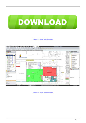
8PlugIn Installation Manualguidelines and ARE WEARING A CONDUCTIVE WRIST STRAP connected to a conductive workingsurface. Remove the top cover and electronic board from the ECU baseplate by removing the four retainingscrews, very carefully and evenly pry the lid off using blade screwdrivers. The electronic board may comeaway with the lid. When removing the electronic board hold it only by the plastic header and place it insidethe lid.4. Fit the Link Plug-In ECU: Remove the ECU from its packaging and position it with the electronic boardfacing up, place the factory baseplate onto the ECU lid. Remove the tape securing the electronic board tothe lid. Secure the base-plate and lid together with the four cap screws supplied with the ECU. Place thefactory electronic board and lid in the packaging your Link ECU came in for its protection.5. Mount the Link 350Z plug-in ECU in the position of the factory ECU.6. Install a vacuum line from the MAP port on the ECU to the intake manifold of the engine. The engine has aconvenient port for connection under the front plastic engine cover. 2 0 1 7 Link
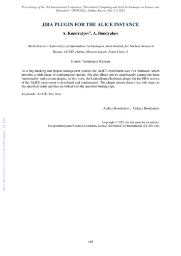
Installation97. Connect the ECU to the factory wiring loom, use the lever on the connector to make sure the connector issecured into the ECU.8. Do NOT attempt to start the vehicle. Proceed to read through the remaining sections of this manual first. 2 0 1 7 Link
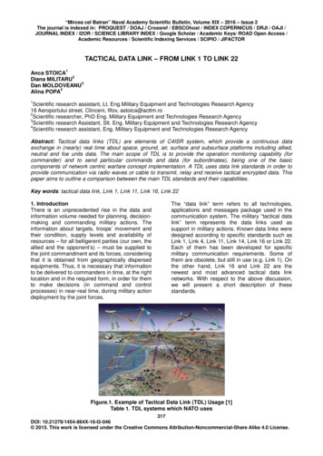
104PlugIn Installation ManualAdditional SensorsG4 Plug-In ECUs offer various options for the installation of additional sensors and devices. As a minimumit is recommended that all ECUs are installed with a Manifold Absolute Pressure (MAP) sensor and IntakeAir Temperature (IAT) sensor. These parts can be purchased if required from your nearest Link dealer.4.1MAP SensorIt is important that the pressure source for a MAP sensor be taken from a stable pressure source after thethrottle body. It is common to 'T' into the fuel pressure regulators pressure signal. Do NOT share this signalwith other devices such as boost gauges or blow off valves.4.1.1350ZLinkThe G4 350ZLink Plug-In ECU supports several options for fitting of a MAP sensor. Any one of the followingoptions can be used:1. Internal MAP Sensor – To ease installation the G4 350ZLink ECU is fitted with an internal MAP sensor.This sensor is rated to 4.0 Bar absolute pressure (3.0 Bar of boost). The internal MAP sensor is wired toAn Volt 9.2. MAP Sensor Wired Through AFM – To avoid running additional wires into the engine bay, a MAP signalcan be brought in through the AFM signal wires. The AFM is wired to An Volt 3. Refer to factory wiringmanuals for AFM wiring connections. Make sure the AFM can not be reconnected.3. MAP Via Expansion Connector - The expansion connector provides power, ground, and analog channelsfor the connection of a MAP sensor.Make sure that the correct An Volt channel has been selected as MAP sensor in PCLink and a MAPcalibration has been performed before attempting to start the vehicle.4.2IAT SensorIt is highly recommended that an IAT sensor be fitted in all applications to provide an input for correction offuel and ignition based on the engines air charge temperature.An IAT sensor should be fitted in the intake system in a location that accurately represents intaketemperature. The most common location is just prior to the throttle body. Installing in the manifold is notrecommended due to heat soak issues. A fast response sensor must be used in all forced inductionapplications.4.2.1350ZLinkThe G4 350ZLink Plug-In ECU supports several options for fitting of an IAT sensor. Either of the followingoptions can be used:1. Factory Fitted IAT Sensor – 350Z models are factory fitted with an IAT sensor in the MAF. This sensor iswired to An Temp 2.2. IAT Through Expansion Connector - The expansion connector provides ground and a temperature channelfor the connection of an IAT sensor.As the factory IAT sensor is not located in the intake manifold it is recommended to fit an aftermarket IATsensor to the intake manifold and use the MAF IAT wiring or expansion connector to connect the sensor tothe ECU.4.3Expansion ConnectorThe expansion connector is provided to allow easy connection of additional ECU inputs. An “expansion cable”needs to be purchased from your Link dealer. 2 0 1 7 Link
Additional Sensors11Important points when wiring to the expansion connector:Do not overload the 5V Out pin. Although this is protected against ECU damage the 5V out signal alsoprovides power for other sensors.Do not connect the ground pin to chassis ground. This could cause ground loops and introduceunnecessary interference. Use this pin only to ground external sensors that are isolated from chassisground.4.3.1350ZLinkThe following expansion connector inputs/outputs are provided:Expansion Connector 1:GndSensor Ground Only 5VLow Current 5V SupplyAux 15Auxiliary OutputAux 14Auxiliary OutputDI 8Digital InputDI 9Digital InputAn Volt 8Analog 0-5V inputAn Temp 4Temperature sensor inputDI 11Digital InputAux 16Auxiliary OutputAux 8Auxiliary Output 5VLow Current 5V SupplyGndSensor Ground OnlyExpansion Connector 2: 2 0 1 7 Link
125PlugIn Installation ManualPC TuningG4 ECUs require PC/laptop tuning using the PCLink Tuning Software application running on a Windowsbased computer. PCLink may be downloaded from www.LinkECU.com. Note that when new versions ofPCLink are released they are posted on the website and may be downloaded at no cost. Also note that G4 ECUs must be used with the correct version of PCLink.IMPORTANT!The G4 ECU has on board USB.BEFORE connecting the ECU to your laptop, the USB drivers must be installed.Failure to install the drivers on your laptop first may result in windows assigningincorrect drivers. These drivers will not work with the G4 ECU and are difficult touninstall. The correct USB drivers are installed as part of PCLink installation, asdescribed in the following section. Should internet download not be practical, acopy of the drivers on CD can be obtained from your nearest Link dealer.5.1Installing PCLinkDue to the frequent updates PCLink is no longer shipped with each ECU. You will be required to downloadthe latest version of PCLink from: www.LinkECU.comShould access to an Internet connection be impractical, download the latest version of PCLink elsewhere to aUSB drive, and then install on your laptop.Installing from the web1. Go to the above website and navigate to the downloads and software updates section.2. Download the latest version of PCLink. When prompted to run or save the file, select save. It isrecommended to save this file on the desktop.3. Double click the saved file and follow on screen instructions.4. When prompted to install USB drivers, select yes. This may take some time.5. When installed, open PCLink by double clicking on the icon that has been placed on the desktop.5.2Communicating With Your ECUAfter PCLink installation, you will be able to connect the G4 ECU to the laptop to perform set-up and tuningwork.1. Connect the ECU to your laptop using a Link G4 ECU USB Cable. If not supplied with the ECU, thesecan be purchased from a Link dealer. No other adapter or cabling is required. Connect the cable to theconnector labelled USB.2. If this is the first time you have connected a G4 USB ECU to your laptop follow the driver installationinstructions that appear. When prompted if you want to install drivers select 'Continue Anyway'.3. Start PCLink by double clicking on the PCLink icon on the windows desktop.4. Switch the key to the ON position. This will provide power to the ECU.5. In PCLink, under the 'Options' menu, select 'Connection'. The connection options dialogue will open.Select the correct COM Port number from the drop down list or select auto for automatic com portdetection.6. PCLink offers both mouse and keyboard control. To establish a connection between the PC and ECUpress the F3 key. The same process can be used to disconnect. If a successful connection isestablished, PCLink will download settings from the ECU, otherwise you will be warned that an error hasoccurred.7. Make sure the connection shows “ONLINE” in the top right corner of PCLink.8. To permanently STORE any changes made to the ECU press F4. If this is not done before turning theECUs power off all changes made will be lost. 2 0 1 7 Link
Pre-Start Configuration613Pre-Start ConfigurationBefore starting the vehicle, important pre-start configurations need to be made.6.1Firmware VersionIt is recommended that the Link G4 ECU is running the most up to date firmware. Firmware versioninformation can be obtained by connecting to the ECU with PCLink and selecting 'ECU Information' under theHelp menu.The latest firmware can be downloaded from our website with PCLink.It is recommended that this is performed by an experienced Link dealer as new features may need to beproperly configured.The firmware can be updated by selecting 'Update Firmware' under the 'ECU Controls' menu in PCLink.Follow the on screen instructions to complete the firmware update process.6.2Base ConfigurationAll G4 Plug-In ECUs are shipped with base configuration settings. Note that these are provided to reduceinitial setup and tuning times. They are NOT recommended tuning values. PCLink includes baseconfigurations for various models. Download the appropriate base configuration into your ECU with PCLinkby connecting to the ECU (described in the Connecting To PCLink section of this manual), then selecting'Open' under the 'File' menu. Select the appropriate .pcl file and then select 'Open'. Downloading largeconfiguration files can take up to a few minutes. Be patient and acknowledge any messages PCLink shows.6.3MAP Sensor CalibrationAt key on and engine not running the Manifold Absolute Pressure (MAP) Sensor should always match theBarometric Absolute Pressure (BAP) Sensor. As well as providing altitude correction, the BAP sensor alsoallows the MAP sensor to be calibrated prior to tuning.Link G4 ECUs use an on-board barometric sensor that is calibrated prior to dispatch. This ensures that allPCLink Tuning Software programs (pcl Files) give a consistent state of tune throughout the ECU range. Thisallows a PCL file to be transferred between G4 based ECUs giving an equivalent state of tune providing allfactors affecting volumetric efficiency are equal.Without the ability to calibrate all the available types of MAP Sensors to the BAP Sensor there would besignificant affects on the accuracy of the resulting tune, especially when tuning with Manifold GaugePressure (MGP) as a load index.To calibrate the MAP sensor:1. Connect a laptop/notebook PC to the ECU and connect to the ECU using PCLink.2. Under the Analog Channels menu, select the An Volt channel that has been wired to the MAP sensor.Select the correct MAP Sensor Type.3. Under the 'Options' menu, select 'MAP sensor calibration'.4. Follow the on screen instructions.5. Select the 'Analog Inputs' tab in the runtime values section of PCLink (lower part of the screen).6. Compare the MAP and BAP values and ensure they have a similar reading (within 1 kPa).7. Perform a 'Store' by pressing F4.6.4TPS CalibrationThe Throttle Position Sensor (TPS) is used by the ECU to calculate various engine management parametersused by functions such as idle speed control,acceleration enrichment and motor sport features. It isimportant that the ECU knows when the throttle is open and closed (or part way in between). The followingprocedure calibrates the ECU to match the TPS and is for engines using a cable driven throttle: 2 0 1 7 Link
14PlugIn Installation Manual1. Connect a laptop/notebook PC to the ECU and connect to the ECU using PCLink.2. Under the Analog Channels menu, ensure that the correct An Volt channel is set to 'TPS (Main)'. Refer tothe pin functions section of this manual for details.3. Under the 'Options' menu, select 'TPS calibration'.4. Follow the on screen instructions.5. Select the 'Analog Inputs' tab in the runtime values section of PCLink (lower part of the screen).6. Ensure the Throttle Position value reads 0% when the throttle is closed and 100% when fully open.7. Perform a 'Store' by pressing F4.For engine setups that use Electronic Throttle Control the Foot Position Sensor (FPS) and Throttle PositionSensor (TPS) need to be calibrated.For Link Plug-in ECUs see PCLink Help G4 ECU Tuning Functions Electronic Throttle ElectronicThrottle Control TPS and FPS Calibration6.5IAT Sensor SelectionThis section only applies when an Intake Air Temperature (IAT) sensor has been wired and fitted to the intakesystem. It is important that the ECU is calibrated to match the sensor installed in the engine. This procedureis as simple as selecting the correct sensor type as follows:1. Connect a laptop/notebook PC to the ECU and connect to the ECU using PCLink.2. Click on 'Analog Channel' in the configuration tree.3. Select the An Temp channel the sensor has been wired to.4. Ensure that channel (and only that channel) is set to 'Inlet Air Temperature'.5. Select the correct 'Temp Sensor Type'.6. Select the 'Analog Inputs' tab in the runtime values section of PCLink (lower part of the screen).7. Ensure that IAT reads the correct temperature.8. Perform a 'Store' by pressing F4.6.6Input and Output SetupAs the Link G4 Plug-In ECUs are designed to run several models there are a few items that must be set-upto make the ECU specific to your model.The Pin Functions section of this manual gives a list of the functions of each channel based on the targetvehicle.It is the tuners responsibility to make sure that the following channels are set-up correctly for the vehiclemodel the ECU is fitted to:All Auxiliary Output ChannelsUse the 'Te
property resulting from the use of the ECU or any failure of or defect in the ECU whether by general, . microprocessor controlled Engine Management System. G4 software employs high resolution fuel and ignition tables with configurable load and RPM centres. When . 2003 to 2006 Nissan Skyline V35 2003 to 2006 Infinity G35