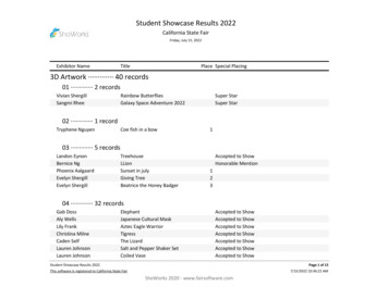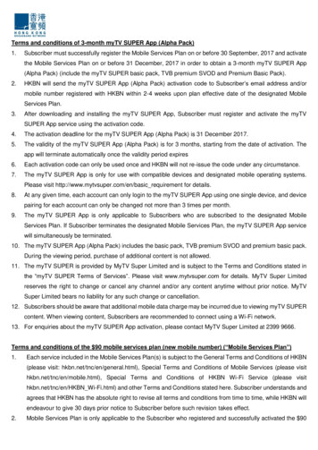
Transcription
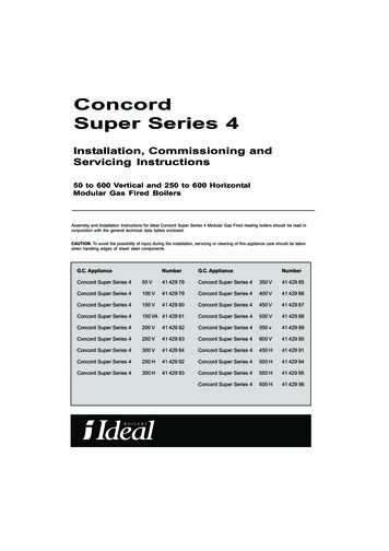
ConcordSuper Series 4Installation, Commissioning andServicing Instructions50 to 600 Vertical and 250 to 600 HorizontalModular Gas Fired BoilersAssembly and Installation Instructions for Ideal Concord Super Series 4 Modular Gas Fired heating boilers should beread in conjunction with the general technical data tables enclosed.CAUTION. To avoid the possibility of injury during the installation, servicing or cleaning of this appliance care should be takenwhen handling edges of sheet steel components.G.C. ApplianceNumberG.C. ApplianceNumberConcord Super Series 450 V41 429 78Concord Super Series 4350 V41 429 85Concord Super Series 4100 V41 429 79Concord Super Series 4400 V41 429 86Concord Super Series 4150 V41 429 80Concord Super Series 4450 V41 429 87Concord Super Series 4150 VA41 429 81Concord Super Series 4500 V41 429 88Concord Super Series 4200 V41 429 82Concord Super Series 4550 V41 429 89Concord Super Series 4250 V41 429 83Concord Super Series 4600 V41 429 90Concord Super Series 4300 V41 429 84Concord Super Series 4450 H41 429 91Concord Super Series 4250 H41 429 92Concord Super Series 4500 H41 429 94Concord Super Series 4300 H41 429 93Concord Super Series 4550 H41 429 95Concord Super Series 4600 H41 429 96
GENERALCONTENTSAssembly.18Electrical data .18INTRODUCTIONThe Ideal Concord Super range of boilers is suitable forconnection to fully pumped, open vented or pressurisedcentral heating, indirect domestic hot water and combinedsystems - in commercial and industrial premises.Note. British Gas certification does not apply to pressurisedsystems.Exploded diagrams .19DUTYCombustion Data Sheet .36Commissioning and Testing.22The range of boiler is suitable for: combined indirect pumpeddomestic hot water and central heating systems; independentindirect pumped domestic hot water or central heatingsystems.Fully pumped systems may be open vented or sealed.General .3Installation requirements .3Technical data .4Boiler house clearances.6Flue requirements .7Design requirements .12Electrical data .14Installation .8The range of boiler is NOT suitable for:1. Gravity DHW systems.2. Gravity heating systems.3. Direct domestic hot water supply.FOUNDATIONThe boiler must stand on a non-combustible floor(i.e. concrete or brick) which must be flat, level and of asuitable load bearing capacity to support the weight of theboiler (when filled with water) and any ancillary equipment.Dimentional data .8GAS SAFETY (INSTALLATION AND USE)REGULATIONS, 1994Service & Fault Finding.27All gas appliances must, by law, be installed by competentpersons, e.g. CORGI in accordance with the aboveregulations. Failure to install appliances correctly could lead toprosecution.Cleaning .27Replacements .30Short list of parts .33It is in your own interest, and that of safety, to ensure that thelaw is complied with.In addition, the installation must comply with the relevantBritish Standard Specifications and Codes of Practice:IGE-UP-1Purging Procedures for Non-domestic GasInstallations and Soundness Testing Proceduresfor Industrial and Commercial Gas Installations.IGE-UP-2Guidance for Installation of Gas Pipework Boostersand Compressors for Customers Premises.BS. 6644Installation of Gas Fired Hot Water Boilers ofRated Inputs between 60kW and 2 mW.BS. 6880Central Heating by Low Pressure Hot Water.IM/11Flues for Commercial and Industrial Gas FiredBoilers and Air Heaters.IM/22Installation Guide for High Efficiency (Condensing)Boilers (industrial and Commercial Appliances).Note: The Ideal Concord Super is a partiallycondensing boiler therefore the condensatedrain should be run in accordance with IM/122.BS. 5440:2Specification for Installation of Ventilation forGas Appliances.CP 342.2Centralised Hot Water Supply.Health and Safety Document No. 635.The Electricity at Work Regulations 1989.Note: All threaded gas and water connections must be sealedusing appropriate jointing compound.2Concord Super Series 4 - Installation
GENERALINSTALLATION REQUIREMENTSBOILER DESCRIPTIONMODULE DESCRIPTIONEach boiler consists of;Each module can be sub-divided into 4 main elements:(a) The insulated stainless steel casing with flue outlet, fluecoupling point and condensate drain.(a) The heat exchanger, which consists of finned coppertubes expanded into cast iron end plates, and cast ironflow and return elbows (refer to Frame 15).(b) The heat exchanger module(s).(c) The module control pack.(d) Wiring centre with high & low voltage wiring harnesses.and, in the case of multi-module boilers.(e) Gas header - complete with individual module gasservice taps and mains inlet gas tap.(b) The gas line, which supplies and regulates the gas flow tothe burner (refer to Frame 17).(c) The fan assembly, which draws gas (from the injector) andair, mixes them and supplies the mixture to the burner.(Refer to Frame 16).(d) The electrical control assembly.(f) Flow and return water headers.MODE OF OPERATION(g) Each boiler is supplied with instructions for installationand use.The normal mode of operation of the boiler is preceded, incertain conditions, by a period in which the complete boilercasing is given a three volume air change. The air change isan important safety feature of the European requirements,with which the boiler is designed to comply.The air change will occur whenever the boiler goes from asituation of no modules firing to a situation of one modulefiring. This includes morning start-up and those occasions oflow load when the last module firing goes off on itsthermostat (or external controls) and is called again.The air change will NOT occur if one or more modules arefiring and a further module is called.The three volume air change period operates as follows, inthe case of multi-module boilers: All the module fans areenergised and run for a period of not less than 30 seconds.At the end of this period all the fans switch off.The 50kW boiler is supplied with a module gas service taponly.Each module is connected in parallel across the flow andreturn water headers, ensuring that water is flowing throughall of the modules at all times.The Ideal Concord Super range of boilers provides goodload matching & sequence control by the following method:As the load on the boiler decreases so the return watertemperature increases.Each module is fitted with an electronic thermostatcapable of being set to within 0.5 C. These thermostatssense the return water temperature.Once the flow temperature reaches 82 C (i.e. the returnreaches 71 C) the modules are set to switch off at intervalsto maintain the flow at 82 C 3 C.With basic controls the modules switch off from left toright and from top to bottom. Thus the top left module isalways the first to go off and the bottom right the last. Thestandard wiring centre, on the side of the boiler, is theconnection point for the mains supply, the low gas inletpressure and low water pressure switches - provided forboiler protection. The centre also provides facilities for thewiring in (via voltage free connections) of remoteindicators/alarms, for ‘burner on’, ‘lock out’ and‘overheat’. (Indicating that at least one module is in thesignalled condition).Facility is also provided for the connection of the ‘BoilerManagement System’. Additional controls such as waterflow switch, programmer, energy management systemsetc. may also be used.After a delay of approximately 1 second, the fan of themodule being called begins its 15 second pre-purge period.Refer to Frame 30.In the case of single module boilers: only its own 15 secondnominal prepurge period occurs.When the electronic adjustable control thermostat calls forheat, the fan is switched on and purges the combustionchamber for 15 seconds. At the end of this time the ignitionsequence starts; the control box delivers a spark from theignition electrode to the burner and the gas valves areopened.Gas is delivered, via the injector, to the distribution plate atthe inlet to the fan. This pre-mixes the gas with the air whichthen passes from the fan through a multi-hole plate to theburner, where it is ignited. The flame is sensed via theionization electrode and the controls keep the valves openuntil the thermostat is satisfied.The module is protected against blockage of the burner, heatexchanger or flue, and against fan failure by the gas/aircontrol. This senses the difference in pressure across themulti-hole plate and controls the gas injector pressureaccording to the amount of air flowing.After combustion, the products flow past the finned coppertubes and through the gas distribution screen into the boilercasing. In doing so, heat is given up to the water flowingthrough the tubes.Concord Super Series 4 - Installation3
GENERALTECHNICAL DATATable 1.Boiler50 VNo. of modulesHeat outputHeat inputFlue gas massvolume*at 120 C (248 F)150 V200 V250 V300 V150 VA250 H300 H12345635650100150200250300150250300Btu/h x u/h x 10Gas rate100 8m3/h5.511.016.522.127.633.116.527.633.13ft. 32290348174290348Required waterl/s1.072.143.214.285.356.423.215.356.42flow rate 045054012.5 kN/m2 (50 in.w.g.)Hydraulic resistanceMinimum static head**2 m (6.5 ft.)Maximum static head60.0 m (197 ft.)Electricity supplyPower consumption6.0 bar (85 lb/in2)230 V 50 Hz,W90180270360Gas supply pressure †45054020.0 mbar (8 in.w.g.)Boiler l)in.30.856.475.361.081.181.161.058.358.3Boiler 1.576.6106.698.984.0107.099.0and .0218.0Weight 464580696348580696Weight of gas &kg.---34.053.659.489.494.353.492.296.7water headers ‡lb.--75118131197200118203213Water gal.1.02.64.65.98.39.94.98.89.9Flow and returnmm405065658080658080connection ††in.11 2212 212 23Gas connectionRc3 4111 411 411 2in. BSP3 4111 411 4125175200250Boiler depth (overall)Weight of casingFlue pipe size698 mm (27.4 in.)mm312 23311 211 411 211 211 211 211 411 211 2250300200250300(Nominal bore) †††in.57810101281012Flue socket sizemm159213238288288339238288339in.61 483 893 8113 8113 8133 893 8113 8133 8Injector size7.3 mm (0.28 in.)Type of gasNatural gas (G20) onlyNotes:‡Total weights of all headers, fully assembled.*Flue gas volumes are calculated from a calorific value of38.4 MJ/m3 (1,031 Btu/ft.3) at 15 C and 1.013 bar based on a CO2 content of 9.0%.†The minimum gas supply pressure is with all modulesfiring.**For further information on minimum head requirementsrefer to page 9.4†† Flange size; refer to BS. 4504.††† For 150 VA, 250 V and 250 H models ONLY, a flueadaptor is supplied as standard.Concord Super Series 4 - Installation
GENERALTECHNICAL DATATable 2.Boiler350 VNo. of modulesHeat outputHeat inputGas rateFlue gas massvolume*at 120 C (245 F)kW400 V450 V500 V550 V600 V450 H500 H550 H600 /h x 470.4592.2588.0648.8705.6529.2588.0646.8705.6Btu/h x .644.149.755.260.766.249.755.260.766.23ft. uired 2.84flow rate 0155.1169.2810900990108012.5 kN/m2Hydraulic resistanceMinimum static head **2mMaximum static head60.0 m (197 ft.)Electrical supplyPower consumption(50 in.w.g.)(6.5 ft.)6.0 bar (85 lb/in2)230 V 50 Hz,W630720810900Gas supply pressure †99020.0 mbar1080(8 in.w.g.)Boiler Boiler g.134126197190197190182175Boiler depth (overall)Weight of casing1350 mm182(53.1 in.)175and insulationlb.295278435418402386435418402386Weight 510521168128214021052116812821402Weight of gas &kg.260263311313315318298300302304water headers ‡lb.573580686690694701657661665670Water Flow and returnmm100100125125125125125125125125connection ††in.4.04.05.05.05.05.05.05.05.05.0Gas connectionRc2222222222in. BSPFlue pipe inal bore) †††in.14141616181816161818Flue socket sizemm400400450450501501450450501501in.153 4153 4171 4171 4193 4193 4173 4173 4193 4193 4Injector sizeType of gasConcord Super Series 4 - Installation7.3 mm (0.28 in.)Natural gas (G20) only5
GENERAL1 RECOMMENDED BOILER-HOUSECLEARANCES 50 - 300kW2 RECOMMENDED BOILER-HOUSECLEARANCES 350 - 600kWAll dimensions in millimetres (inches)All dimensions in millimetres (inches)The installation must also conform to current buildingregulations, any requirement of the local authority healthand safety executive, gas region, insurance companiesand the Health and Safety at Work Act 1974. All wiringmust conform to I.E.E. (BS. 7671) regulations for theelectrical equipment of buildings.The boiler modules are very quiet in operation and noadditional noise soundproofing is required.LOCATIONThe floor must be flat, level, and capable of supporting theweight of the WET boiler pipework. In addition concrete floorsmust be sealed. The siting of the boiler must be in accordancewith the guidance given in BS. 6644 and with reference tominimum boiler-house clearances. Refer to Frames 1 & 2.CONNECTION TO GAS SUPPLYThe gas installation MUST be in accordance with the requirements of the local gas region (refer also IM/16).The gas supply must be capable of maintaining a minimumpressure of 15.0 mbar (6 in.w.g.) at the inlet to the boiler, withall modules firing.Gas consumption is given in Tables 1 & 2.The boilers are for use with NATURAL GAS ONLY.FLUE REQUIREMENTSOpen flue, induced draught and tan diluted systems may beused but must comply with the following basic requirements:1A draught diverter MUST NOT be fitted.2. A draught stabiliser MUST be fitted to ail types of fluesystems within 1 metre of the flue outlet and set to controlthe draught in the casing between neutral and 0.2 mbar (0.08in.wg.) irrespective of flue height or number of modules firing.Refer to Frames 3 and 4 for further guidance.3. ALL fIue systems must be insulated and/or lined andimpervious to acid condensate.Prefabricated chimneys must have a ’U’ value of no greaterthan 1.4 W/m2 C at 540 C (0.25 Btu/h ft.2 F at 1000 F.)4. Drainage must be provided at the base of the chimney orliner. All boiler casings are fitted with a condensate drainpoint - refer to Frame 14.6BOILER HOUSE CLEARANCES5. For fan diluted or induced draught systems, airflow/pressure switches MUST be fitted to protect againstfan failure. Switches should be set to open if the air flowreduces by more than 15%.6. Flue products must not be allowed to enter the boilerhouse or adjacent buildings.7. Refer also to BS. 6644 and to the British Gas PublicationIM/11 - ‘Flues for Commercial and Industrial Gas FiredBoilers and Air Heaters’ and IM/22 for further guidance.AIR SUPPLYDetailed recommendations for air supply are given in BS. 5440:2and BS. 6644 which MUST be consulted before proceeding.Contamination of the air supply from any external sourcemust be avoided, with particular reference to dust, insulationdebris and flue products. Concrete floors must be sealed.If any work is to be carried out in the boiler-house which islikely to generate dust (e.g. structural alterations or thelagging of pipework) it is recommended that the boiler is shutdown and the modules covered with a dust sheet, otherwisethe boiler will require cleaning and servicing.1. In particular, the contamination of the air supply withchlorides must be avoided as they will cause the deterioration of the aluminium fan impellor.2. The boiler-house requires ventilation openings at BOTHhigh and low levels, direct from the outside. AllowancesMUST be made for stabiliser dilution in all cases.3. Mechanically forced ventilation systems must includeprovision for boiler shut down in the event of tan failure.4. High speed air streams within the boiler house must beavoided.5. Extraction mounted ventilation fans alone are NOT permitted.6. The minimum effective areas of the permanent air ventsdirect from the outside by natural ventilation are as follows:Low level- 540 cm2 plus 4.5 cm2/kW in excess of 60kWtotal rated input.High level- 270 cm2 plus 2.25 cm2/kW in excess of 60kWtotal rated input.Concord Super Series 4 - Installation
FLUE REQUIREMENTSGENERAL3 APPLICATION OF DRAUGHT STABILISER - SINGLE BOILER INSTALLATIONINDUCED DRAUGHTNote: The discharge from both types of system MUST notallow recirculation of combustion products into the boilerhouse or adjacent buildings.FAN DILUTED FLUE (FDF) SYSTEMNote: Air intake and discharge should be on the same outsidewall face. Design must comply with British Gas requirements-refer page 5 and Publication IM/11.All dimensions in millimetres (inches)4 FLUEING - GENERAL GUIDANCE BOILER INSTALLATIONNotes:The draught at the boiler casing must be controlled betweenneutral and 0.2 mbar (0.08 in. w.g.) negative irrespective ofthe number of modules firing.The draught stabiliser must be fitted within 1 metre of theboiler casing.To achieve the minimum neutral draught condition a verticalflue length of 2 metres is needed plus whatever extra heightis necessary to overcome the resistance of any bend orductwork between the boiler casing and the vertical flue.Contact should be made with the Customer Care departmentof Caradon Heating for further advice and information on thissubject. Tel: 01482 498376All dimensions in millimetres (inches)Concord Super Series 4 - Installation7
8All dimensions in millimetres (inches)50kW Verticalfp Foot Projectiongc Gas Connection100kW Vertical150kW Vertical150kW Vertical/AlternativeINSTALLATIONDIMENTIONAL DATA5 BOILER DIMENSIONS 50kW - 150kW ModelsConcord Super Series 4 - Installation
Concord Super Series 4 - InstallationAll dimensions in millimetres (inches)200kW Verticalfp Foot Projectiongc Gas Connectionrc Return Connection250kW / 300kW Vertical250kW / 300kW HorizontalDIMENTIONAL DATAINSTALLATION6 BOILER DIMENSIONS 200kW - 300kW Models9
10All dimensions in millimetres (inches)350kW - 400kW Vertical450kW - 600kW Vertical450kW - 600kW Horizontalgc Gas ConnectionINSTALLATIONDIMENTIONAL DATA7 BOILER DIMENSIONS 350kW - 600kW ModelsConcord Super Series 4 - Installation
DIMENTIONAL DATAINSTALLATION8 SITE ASSEMBLY - 600kW Vertical boilerNote.1. To aid the assembly procedure, on the flow &return manifolds and the flow & return spools,theflanges are left loose for site welding.2. The double M/F elbows (16) are to enable easeof fit and squareness.LEGEND1. Insulated boiler casing (c/w feet).2. 80 nom. bore elbow.3. Flow manifold (long).4. Flow and return headers.5. Flexible bellows unit.6. Blank flange.7. Gas header complete with gas cocks.8. Rc 11 2 union elbows.9. Space nipple.10. Flow and return spools.11. Rc11 2 elbow.12. Space nipple.13. Short space nipple.14. Main gas cock (not shown).15. Rc 2 twin elbow (with two hex bushes).16. 11 2 M/F elbow.17. Return manifold (short).9 SITE ASSEMBLY - 600kW Horizontal boilerNote.1. To aid the assemblyprocedure, on the flow &return manifolds and the flow& return spools, the flangesare left loose for site welding.2. The double M/F elbows (12)are to enable ease of fit andsquareness.LEGEND1. Insulated boilercasing (c/w feet).2. 125 nom. bore elbow.3. Flow manifold (long).4. Flow and return headers.5. Flexible bellows unit.6. Blank flange.7. Gas header completewith gas cocks.8. Rc 11 2 union elbows.9. Short space nipple.10. Main gas cock (not shown).11. Rc 2 twin elbow (with two hex bushes).12. 11 2 M/F elbow.13. Return manifold (short).Concord Super Series 4 - Installation11
GENERALDESIGN REQUIREMENTS7. The minimum air requirements by mechanical ventilationare as follows:Table 3 - MECHANICAL VENTILATION FLOW RATES.Type of boilerForced/induceddraught boilersFlow rate per 1000kW total ratedheat inputExtract airInlet air(ventilation)(combustionventilation)0.90 m3/s0.60 m3/sA purpose designed flueing ventilation system based solelyon a high level permanent opening to an otherwise sealedboiler-house or compartment may be used, provided thatspecialist advice is taken, and that the combustion air andventilation requirements of the boiler is provided in line withBS. 6644. In addition to this, the boiler house temperaturemust be prevented from exceeding 32 C.WATER CIRCULATION SYSTEMDESIGN REQUIREMENTSIdeal Concord Super gas boilers are intended for use inconjunction with FULLY PUMPED, OPEN VENTED orPRESSURISED systems - subject to the requirementsdetailed below. They are NOT suitable for use on gravitycirculation systems.Note. In some cases, pump manufacturers will require a headas high as 12m (40ft). This must be allowed for and theminimum head increased accordingly. Refer to Frame 10 forfurther clarification.Safety ValveA safety valve must be sized and fitted in accordance withBS. 6644. The valve should be set at 0.7 bar (10 lb/in 2 )above the available static head of water over the boiler.The maximum safety valve setting is 0.7 bar (10 lb/in2) abovethe maximum design operating head of 6.0 bar (85 Ib/in2), i.e.6.7 bar (95 Ib/in2).Table 4 - VENT, COLD FEEDThe open vent and cold feed pipe sizes must comply with BS.6644 and must be of the following minimum size.Boiler50 V100 V, 150 V200 V, 250 V, 300 V150 VA250 H, 300 H350 V - 600 V450 H - 600 HCold feednominal dia.19 mm25 mm32 mm25 mm32 mm38 mm38 mmOpen ventnominal dia.25 mm32 mm38 mm32 mm38 mm50 mm50 mmWater Flow Rate1.07 l/s (14.1 gal/min) 10% through each module.Thus a six module boiler requires 6.42 l/s (84.6 gal/min)volume flow rate. Refer to Tables 1 & 2 for other boilers.Note. Failure to maintain this flow rate will result in operationof the module overheat cut off device.The boilers are suitable for operation when connected tosystems requiring lower flow rates than those quoted aboveand to systems where the volume flow varies with load,PROVIDED they are installed in accordance with Frame 10.Any other method of installation should be discussed withCARADON HEATING Ltd. before proceeding.DrainThe drain valve must comply with BS. 2879 and be operatedwith a removable key.Pressure GaugeThe water pressure gauge and temperature gauge must thefitted in accordance with BS. 6644.Water flow switchA water flow switch must be fitted to protect the boilerfrom pump failure.Hydraulic Resistance - refer Graph 1Graph 1 - HYDRAULIC RESISTANCEWhen operating at the correct volume flow rate given above,the hydraulic resistance of all Ideal Concord Super boilers is12.5 kN/m2 (50 in.w.g.).Pump Over-runA pump over-run time of 30 seconds minimum must beallowed for on plant shutdown.Maximum Static Head60.Om (197 ft.), i.e. maximum operating pressure 6.0 bar (85 Ib/in2).Minimum Static HeadMinimum static head requirements for open vented systemsmust comply with boiler design characteristics, pump manufacturer’s requirements and the requirements of the Healthand Safety executive Publication PM5.In order to comply with the above, a minimum static head of 2m(6.5 ft), i.e. 0.20 bar (3 lb/in2) will be adequate under most operatingconditions, measured either from the highest circulating point of thesystem or from the boiler when the boiler house is roof mounted.12Concord Super Series 4 - Installation
DESIGN REQUIREMENTSGENERALGENERAL GUIDANCE ON APPLICATIONSFrame 10 is intended to provide basic information only on theapplication of the Ideal Concord Super boiler. British Gasapproval has not been sought in the matter.It is impossible to cover all applications and installers arerecommended to contact Caradon Heating Ltd. if advice on aspecific application is required. It is essential that the waterflow rates given in Tables 1 & 2 be maintained within thelimits stated - therefore any compensating devices must notbe connected to Ideal Concord Super boilers directly butmay be used in conjunction with a mixing header. The mixingheader must be sized at least one pipe size larger than theboiler flow and return manifold size. This will avoid hydraulicinterference between the boiler primary pump and systemzone pumps. The use of a mixing header means thatcompensating controls can be used to operate mixing valveson a variable temperature circuit, without affecting the waterflow rate through the boiler.10 GUIDE TO MINIMUM REQUIREMENTS FOR OPEN VENT - Feed/expansion tank heightand boiler primary circuit.1. Roof top or single storey applications2. Ground floor or basement applicationsLEGEND1. Cold Feed(sizes MUST complywith BS. 6644).2. Open vent.3. Safety valve.4. Water flow switch.5. Dual primary pumps.6. Mixing header- see note above.7. Feed and expansion tank.8. Mixing valve.9. Highest pointin the system.All dimensions in millimetres (inches)Concord Super Series 4 - Installation13
GENERALFrame 10 shows how constant and variable temperaturecircuits can be used on low and high head applications. Thefollowing points should be noted:1. The recommended positions of the cold feed and openvent are shown. Sizes should comply with BS. 6644. ifisolating valves are to be fitted in the flow and return pipesof the boiler they must not isolate the boiler from the openvent, safety valve or cold feed.2. The minimum tank height shown is measured from thehighest point of the system and must be increased, ifnecessary, to comply with pump manufacturers’ requirements.3. The open vent height above tank water level cannot beguaranteed adequate in all circumstances and does nottake into account any instantaneous changes in headbrought about by ancillary equipment operating.4. Water flow switch is shown in its recommended position.It MUST NOT be located on the mixing header whereoperation of zone pumps can cause reduction in flow.5. Production of condensate: When operating normally andthe design return temperature has reached 71 C., theboilers produce no condensate. At lower temperatures theamount of condensate increases. It is normal forcondensate to be produced as the boiler heats up fromcold and, provided the time taken for the return to reach71 C. is not excessive, no harm will result.If, however, large quantities of condensate are producedfor long periods, this can adversely affect burnerperformance and cause the control box to lockout. If thewater content of a system is very large it is advisable toswitch on individual zones from cold, in sequence, with atime delay sufficient to allow the boiler return temperatureto reach 55 C. as quickly as possible.6. Water treatment for hot water and heating boilers.There is a basic need to treat the water contained in allheating and indirect water systems, particularly open ventedsystems. This may be regarded as an essential requirementfor systems incorporating Ideal Concord Super boilers.It is assumed, incorrectly, that because boilers are operatingin conjunction with what is apparently a closed circuit, anopen vented system will not, under normal circumstances,allow damage or loss of efficiency due to hardness salts andcorrosion once the initial charge of water has been heated upa few times.This is not the case. Open vented systems are not completelysealed off from the atmosphere (if proper venting andexpansion of system water is to be achieved). The same tankis used to fill the system with water and it is through the coldfeed pipe that system water expands into the tank as thesystem heats up.Conversely, as the system cools, water is drawn back fromthe tank into the system, together with a quantity of dissolvedoxygen. Also there will be evaporation losses from the surfaceof the tank which, depending on ambient temperature, maybe high enough to evaporate a large portion of the systemwater capacity over a full heating season.For these reasons, even if the system is completely free fromleaks, there will always be corrosion or salt deposition withina heating or hot water system, irrespective of water characteristic unless the initial fill water from the mains is treated.1mm of lime reduces the heat transfer from metal to water by10%.14ELECTRICAL DATALime deposition can also cause noises from the boiler bodyor even premature failure. Corrosion and the formation ofblack iron oxide sludge will ultimately result in prematureradiator and pump failure.Existing systems and, w
Hydraulic resistance 12.5 kN/m2 (50 in.w.g.) Minimum static head** 2 m (6.5 ft.) Maximum static head 60.0 m (197 ft.) 6.0 bar (85 lb/in2) Electricity supply 230 V 50 Hz, Power consumption W 90 180 270 360 450 540 270 450 540 Gas supply pressure † 20.0 mbar (8 in.w.g.) Boiler height mm 782 1432 1912 1550 2060 2060 1550 1480 1480