Transcription
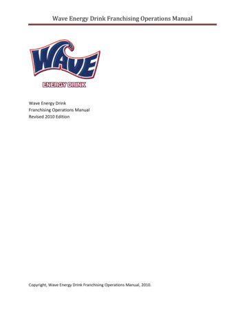
Thermal Analysis of the Drink Cooler DesignCooling beverages using Peltier Cells represents a change from previouscooling methods. The existing product, the Cooper Cooler Blitz Chiller, useda circulating ice water bath to cool a can or bottle via forced convection. Theproduct took advantage of the large amount of energy required to melt iceinto water (the latent heat of fusion, or melting energy, for ice is 334,000Joules/Kilogram), to keep a water bath at or near 0 Celsius. The cold-waterbath was then sprayed over a rotating can to cool the beverage from roomtemperature to serving temperature.The innovation of our product is to eliminate the need of purchasing ormaking ice to create an ice bath at or near 0 Celsius. By cooling the waterbath to the same or comparable temperatures as the existing Cooper CoolerBlitz Chiller, the heat transfer between the can and sprayed water wouldremain the same. Thus the cooling time would remain constant and themajor goal of eliminating use of ice from the product would be achieved. Toaccomplish this task, Peltier Cells were used to remove heat from the water.Peltier Cells utilize the Peltier Effect to create a temperature differentialfrom an electrical differential as heat is forced from one side of the cell tothe other. As current is run through the Peltier Cell, one side becomesextremely hot and one side becomes extremely cold. As the Cell operates,heat must be removed or the Cold side of the cell will begin to warm due toconductive heat transfer through the Peltier Cell.To cool the water, two Peltier Cells are used to chill an aluminum andcopper heat exchanger assembly.Figure 1: Aluminum Heat Exchanger Flow Channel Block1
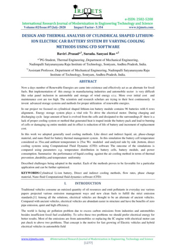
Figure 2: Heat Transfer Block AssemblyWater from the cooling bath is pumped through the flow channels ofaluminum plate. A copper plate is bolted to the top of the aluminum flowchannels to seal the block. Two Peltier Cells are mounted to the top of thecopper plate. The cold side of the Peltier Cell cools the copper plate and thealuminum flow channels and chills the water bath as it flows through thechannels. The hot side of the Peltier is attached to another copper plate. Thissecond copper plate is attached to a commercial CPU heat sink that is usedto remove heat from the two Peltier Cells.To analyze the thermal performance of our product, we will focus on andanalyze four main heat transfer challenges in our product. The first challengeis the capability of the chilled heat transfer channels to cool the water bathbeing pumped through it. The second challenge is the ability of the PeltierCell to cool the aluminum and copper heat transfer block.The third is the ability to manage heat produced in the Peltier Cell duringoperation. The fourth challenge is the ability of the copper plate and heatsink to remove heat from the Peltier Cells and transfer it into the ambientenvironment. By examining the heat transfer at each of these three zones, itis possible to determine the cooling capability of the product.2
Zone 1: Heat Transfer from the Cooling Channels to the Water BathInside of the Aluminum/Copper cooling block, water flows through at aconstant rate (due to the steady state operation of the motor) and is cooled bythe cold walls of block.To calculate the heat transfer from the cooling block to the water bath, aconvective heat transfer model can be used:̅()Equation 1Where q is the total heat transfer rate, ̅ is the average convective heattransfer coefficient,is the surface area of heat transfer, is the surfacetemperature, andis the ambient temperature of the fluid.The variable ofcan be controlled by the design of the flow block and̅channels and can also be controlled by the design the flow channels and bycontrolling the flow of water through the system. The variable ofis atransient property that will change based on temperature of the cooling bathflowing through the flow block while the variables of q and are related bythe performance of the Peltier Cell at different operating amperages.In order to maximize the total heat transfer rate shown in Equation 1, thesystem should be engineered to maximize ̅ and , and to maintain thesmallest possible .To first analyze the system, ̅ needs to be derived. The convective heattransfer coefficient, ̅ , can be derived based on the type of flow occurring inthe pipe: laminar or turbulent. This regime of flow is determined by the flowof water in the channels, the properties of the water flowing, and the pipegeometry, as represented by the non-dimensionless Reynolds Number whichrelates viscous forces in a flow to inertial forces. The equation for theReynolds number is:Equation 2Where is the fluid density, V is the flow velocity, d is the hydraulicdiameter of the pipe, is the fluid viscosity, and is the kinematic viscosity.3
To derive the hydraulic diameter of the flow channel, the following equationwas used:Equation 3Whereis the cross section of the flow channel and P is the perimeter ofthe flow channel. To find the velocity of the water in the channels, thevolumetric flow of water in the channels was experimentally found and themean velocity was derived using the following equation:̇Equation 4Where V is the average flow velocity through the heat sink, ̇ is thevolumetric flow rate supplied by the system pump, and A is the crosssectional area of the flow channels.Thus the combined equation for the Reynolds Number is:̇( )()̇Equation 5Where Re is the Reynolds Number, V is the average fluid velocity, P is theperimeter of the channel, and v is the kinematic viscosity of the water. Thevalues for the terms used and the calculation of the Reynolds number for thechannel,, can be found in Appendix A.Using the three equations above, the Reynolds number was calculated to begreater than 10000 so the flow in the channels could be considered turbulent.The Dittus Boelter equation is a correlation that relates the Reynolds numberof a flow and the Prandlt number of a fluid (a non dimensional number thatrelates momentum diffusivity to thermal diffusivity) to the Nusselt number(a non dimensional number that relates conductive heat transfer toconvective heat transfer in the fluid). The Dittus Boelter equation is:̅̅̅̅Equation 6Where Re is the Reynolds number and Pr is the Prandlt number.4
The Nusselt number can then be used to derive ̅ using the followingcorrelation:̅̅̅̅̅Equation 7Where D is the hydraulic diameter of the pipe and k is the thermalconductivity of the fluid. Thus, the final equation for the convective heattransfer coefficient in the flow channels for turbulent flow is:̅Equation 8̅̇()Equation 9The values of the terms used and the calculations of the convective heattransfer coefficient in the channel, ̅, can be found in Appendix A.Thus, by using the above equations, if the surface temperature or heattransfer rate is known, we can solve for the other using Equation 1. Theseboundary condition are correlated via the heat transfer equations in Zone 2.Zone 2: Heat Transfer from the Peltier Cell through the Copper PlateThe movement of heat from one side of the Peltier Cell to the other is thedriving cooling force in the product. Heat is transferred through the copperplate via conduction. The heat transfer via conduction can be modeled usingthe following equation:()Equation 10Where q is the total heat transfer rate, is the thermal conductivity of thematerial, is the thickness of the material, A is the heat transfer surface areaof the plate, is the hot side temperature of the plate, and is the cold sidetemperature of the plate.5
As shown by Equation 10, the heat transfer is a function of the temperaturedifference between the two sides of the plate ( and ), the plate’s materialproperties (k), and the plate’s geometry (L, A). and will be determinedby system boundary conditions, but the parameters of L, A, and k can all becontrolled. To maximize q, a copper plate was used because of its highthermal conductivity (k), and designed to have large surface area (A), and asmall thickness (L).In Zone 2, represents the temperature of the cooling channel surface andrepresents the temperature of the surface of the Peltier. Thermal contactresistance, or the resistance to heat transfer caused by air small air pocketsthat exist between the surfaces of two rough, touching materials, has beenignored for this analysis. All thermal mated surfaces have you been coatedwith a highly thermally conductive silicon thermal paste to reduce contactresistance.Based on Equation 10 and the assumption of negligible conductive contactresistance, if (the Peltier Cold Side temperature) or the heat flux throughthe system is known known, the heat transfer through the block and into thefluid can be determined.Zone 3: Heat Transfer and Heat Production in the Peltier CellInside of the Peltier Cell, the Peltier Effect or Thermoelectric Effectproduces a thermal differential from a temperature differential. The majorchallenge in using a Peltier Cell is managing the heat produced by the hotside of the Cell. If heat is not removed sufficiently fast enough, then thePeltier Cell will begin to heat, increasing the temperature of the cold sideand decreasing cooling. The heat balance is represented by the followingequation:Heat Rate Peltier Cooling Effect – Joule Heating – Heat Conduction fromHot Side6
These three terms are governed by the symbolic equation for the cold side ofthe Peltier:() Equation 11Where Qc is the heat transfer rates on the cold side of the Peltier Cell, S isthe Seebeck Coefficient (a factor which indicates the effectiveness of thePeltier Cell at creating a temperature differential), I is the electrical currentpowering the Peltier Cell, is the cold side temperature, R is the electricalresistance of the Peltier Cell (a term which will effect the amount of jouleheating which occurs in the cell during operation), and a conductive heattransfer equation using the same variables as was introduced in Equation 3.To maximize heat removal, the first term (the Peltier Cell Cooling Effect)must be maximized and the second two terms must be minimized. One ofthe major problems with our prototype was that we could not run it at fullpower and full cooling capacity due to the difficultly and complexity ofbuilding electronic circuits that run at high amperages. The Peltier Cellsused in the prototype are designed to run at full power while using 9amperes of current, but due to our team’s inexperience with high amperagecircuits and the lack of commercially available high amperage products(most commercial products have a fuse that will trip at 4-5 amps), we wereonly able to achieve a current of 3 amps across the Peltier Cells.Consequently, the prototype was not cooling the prototype to its fullcapacity.Another major factor that controls the effectiveness of the Peltier Cells is thehot side temperature of the Peltier Cell. As the temperature of the hot side ofthe Peltier Cell increases, the overall temperature of the Peltier Cell willincrease due to conductive heat transfer through the cell. By effectivelycooling the hot side of the Peltier Cell, maximum cooling can be achievedon the cold side of the cell.7
Zone 4: Heat Transfer through the Copper Plate and Heat SinkThe cooling of the hot side of the Peltier Cell is essential for operation of theprototype. In the prototype, a copper plate is attached to the two Peltier Cellsto conduct heat from the surface and then is dissipated by a commerciallymade CPU fan-heat sink unit. To model the heat transfer through this sectionof the prototype, the heat transfer from the copper plate and fins of the heatsink will be approximated using conductive and convective heat transferequations respectively.Conduction through the copper plate on the hot side of the Peltier Cell canbe modeled using Equation 3.To calculate the convective heat transfer from the top of the copper plate, thearea and convective heat transfer coefficient of the heat sink must bederived. To simplify the approximation, the heat sink was modeled as anarray of flat plates held at the surface temperature. The extremely highthermal conductivity of the copper heat pipes of the heat sink that connectthe aluminum fin array to the copper plate will keep the fins at a temperatureclose to that of the copper plate surface. To calculate the convective heattransfer coefficient the flow regime (laminar or turbulent) first needed to bedetermined. First, the velocity of the air supplied by the heat sink fan wascalculated using the following equation:̇Equation 4Where V is the average flow velocity through the heat sink, ̇ is thevolumetric flow rate supplied by the fan, and A is the cross sectional area offlow through the heat sink. Given the airflow velocity through the heat sink,the Reynold Number could be calculated using the following equation todetermine the flow regime:(̇)Equation 5Where Re is the Reynolds Number, V is the average airflow velocity, d isthe characteristic channel width, and v is the kinematic viscosity of the fluid.8
Due to the geometry of the heat exchanger plates, the followingapproximation was used:Equation 12Where w is the width between two parallel plates of the heat sink. Thevalues for the terms used and the calculation of the Reynolds Number for theheat sink,can be found in Appendix A. The Reynolds numberwas far less than 2300 indicating that the flow through the heat sink waslaminar. Given laminar flow across parallel plates, the flowing equation canbe used to calculate the Nusselt Number and the convective heat transfercoefficient:̅̅̅̅̅Equation 13Where L is the length of the plate and Pr is the Prandlt number, the nondimensionless number that relates momentum diffusivity to thermaldiffusivity. Thus, the derived form of the equation for the convective heattransfer coefficient in the heat sink is:̅(̇)Equation 14The values of the terms used and the calculations of the convective heattransfer coefficient in the channel, ̅, can be found in Appendix A.Thus, now that
thermal conductivity (k), and designed to have large surface area (A), and a small thickness (L). In Zone 2, represents the temperature of the cooling channel surface and represents the temperature of the surface of the Peltier. Thermal contact resistance, or the resistance to