Transcription
PRELIMINARYCYBLE-214015-01EZ-BLE PSoC Bluetooth 4.2 ModuleEZ-BLE PSoC Bluetooth 4.2 ModuleGeneral Description The Cypress CYBLE-214015-01 is a fully certified and qualifiedmodule supporting Bluetooth Low Energy (BLE) wirelesscommunication. The CYBLE-214015-01 is a turnkey solutionand includes onboard crystal oscillators, trace antenna, passivecomponents, and the Cypress PSoC 4 BLE. Refer to thePSoC 4 BLE datasheet for additional details on the capabilitiesof the PSoC 4 BLE device used on this module.Programmable AnalogThe EZ-BLE PSoC module is a scalable and reconfigurableplatform architecture. It combines programmable andreconfigurable analog and digital blocks with flexible automaticrouting. The CYBLE-214015-01 also includes digitalprogrammable logic, high-performance analog-to-digitalconversion (ADC), opamps with comparator mode, and standardcommunication and timing peripherals.The CYBLE-214015-01 includes a royalty-free BLE stackcompatible with Bluetooth 4.2 and provides up to 25 GPIOs in asmall 11 11 1.80 mm package. The CYBLE-214015-01 isdrop-in compatible with the CYBLE-014008-00 andCYBLE-214009-00 EZ-BLE Modules.The CYBLE-214015-01 is a complete solution and an ideal fit forapplications seeking a highly integrated BLE wireless solution.Module DescriptionLow power mode support Deep Sleep: 1.3 µA with watch crystal oscillator (WCO) on Hibernate: 150 nA with SRAM retention Stop: 60 nA with GPIO (P2.2) or XRES wakeup Four opamps with reconfigurable high-drive external andhigh-bandwidth internal drive, comparator modes, and ADCinput buffering capability; can operate in Deep-Sleep mode 12-bit, 1-Msps SAR ADC with differential and single-endedmodes; channel sequencer with signal averaging Two current DACs (IDACs) for general-purpose or capacitivesensing applications on any pin One low-power comparator that operate in Deep-Sleep modeProgrammable Digital Four programmable logic blocks called universal digital blocks,(UDBs), each with eight macrocells and datapath Cypress-provided peripheral Component library, user-definedstate machines, and Verilog inputCapacitive Sensing Cypress CapSense Sigma-Delta (CSD) provides best-in-classSNR ( 5:1) and liquid tolerance Module size: 11.0 mm 11.0 mm 1.80 mm (with shield) Drop-in compatible with CYBLE-014008-00 andCYBLE-214009-00Cypress-supplied software component makescapacitive-sensing design easy Automatic hardware-tuning algorithm (SmartSense ) 256-KB flash memory, 32-KB SRAM memory Up to 25 GPIOs configurable as open drain high/low,pull-up/pull-down, HI-Z analog, HI-Z digial, or strong output LCD drive supported on all GPIOs (common or segment) Operates in Deep-Sleep mode with four bits per pin memory Bluetooth 4.2 qualified single-mode module QDID: 79480 Declaration ID: D029646Serial Communication Certified to FCC, CE, MIC, KC, and IC regulationsTiming and Pulse-Width Modulation Industrial temperature range: –40 C to 85 C 32-bit processor (0.9 DMIPS/MHz) with single-cycle 32-bitmultiply, operating at up to 48 MHzFour 16-bit timer, counter, pulse-width modulator (TCPWM)blocks Center-aligned, Edge, and Pseudo-random modes Watchdog timer with dedicated internal low-speed oscillator(ILO) Comparator-based triggering of Kill signals for motor drive andother high-reliability digital logic applications Two-pin SWD for programmingUp to 25 Programmable GPIOsSegment LCD Drive Power Consumption TX output power: –18 dbm to 3 dbm Received signal strength indicator (RSSI) with 1-dB resolution TX current consumption of 15.6 mA (radio only, 0 dbm) RX current consumption of 16.4 mA (radio only)Cypress Semiconductor CorporationDocument Number: 002-15923 Rev. **Downloaded from Arrow.com. 198 Champion CourtTwo independent runtime reconfigurable serial communicationblocks (SCBs) with I2C, SPI, or UART functionalityAny GPIO pin can be CapSense, LCD, analog, or digital San Jose, CA 95134-1709 408-943-2600Revised September 7, 2016
PRELIMINARYCYBLE-214015-01More InformationCypress provides a wealth of data at www.cypress.com to help you to select the right module for your design, and to help you toquickly and effectively integrate the module into your design. Overview: EZ-BLE Module Portfolio, Module RoadmapEZ-BLE PSoC Product OverviewPSoC 4 BLE Silicon DatasheetApplication notes: Cypress offers a number of BLE applicationnotes covering a broad range of topics, from basic to advancedlevel. Recommended application notes for getting started withEZ-BLE modules are: AN96841 - Getting Started with EZ-BLE Module AN94020 - Getting Started with PSoC 4 BLE AN97060 - PSoC 4 BLE and PRoC BLE - Over-The-Air(OTA) Device Firmware Upgrade (DFU) Guide AN91162 - Creating a BLE Custom Profile AN91184 - PSoC 4 BLE - Designing BLE Applications AN92584 - Designing for Low Power and Estimating BatteryLife for BLE Applications AN85951 - PSoC 4 CapSense Design Guide AN95089 - PSoC 4/PRoC BLE Crystal OscillatorSelection and Tuning Techniques AN91445 - Antenna Design and RF Layout GuidelinesKnowledge Base Articles KBA97095 - EZ-BLE Module Placement KBA213976 - FAQ for BLE and Regulatory Certifications withEZ-BLE modules KBA210802 - Queries on BLE Qualification and DeclarationProcesses Technical Reference Manual (TRM): PSoC 4 BLE Technical Reference Manual PSOC(R) 4 BLE Registers Technical Reference Manual(TRM) Development Kits: CYBLE-214015-EVAL, CYBLE-214015-01 Evaluation Board CY8CKIT-042-BLE, Bluetooth Low Energy (BLE) PioneerKit CY8CKIT-002, PSoC MiniProg3 Program and Debug Kit Test and Debug Tools: CYSmart, Bluetooth LE Test and Debug Tool (Windows) CYSmart Mobile, Bluetooth LE Test and Debug Tool(Android/iOS Mobile App)PSoC Creator Integrated Design Environment (IDE)PSoC Creator is an Integrated Design Environment (IDE) that enables concurrent hardware and firmware editing, compiling anddebugging of PSoC 3, PSoC 4, PSoC 5LP, PSoC 4 BLE, PRoC BLE and EZ-BLE module systems with no code size limitations. PSoCperipherals are designed using schematic capture and simple graphical user interface (GUI) with over 120 pre-verified,production-ready PSoC Components .PSoC Components are analog and digital “virtual chips,” represented by an icon that users can drag-and-drop into a design andconfigure to suit a broad array of application requirements.Bluetooth Low Energy ComponentThe Bluetooth Low Energy Component inside PSoC Creator provides a comprehensive GUI-based configuration window that lets youquickly design BLE applications. The Component incorporates a Bluetooth Core Specification v4.2 compliant BLE protocol stack andprovides API functions to enable user applications to interface with the underlying Bluetooth Low Energy Sub-System (BLESS)hardware via the stack.Technical Support Frequently Asked Questions (FAQs): Learn more about our BLE ECO System. Forum: See if your question is already answered by fellow developers on the PSoC 4 BLE and PRoC BLE forums. Visit our support page and create a technical support case or contact a local sales representatives. If you are in the United States,you can talk to our technical support team by calling our toll-free number: 1-800-541-4736. Select option 2 at the prompt.Document Number: 002-15923 Rev. **Downloaded from Arrow.com.Page 2 of 42
PRELIMINARYCYBLE-214015-01ContentsOverview . 4Module Description . 4Pad Connection Interface . 6Recommended Host PCB Layout . 7Power Supply Connectionsand Recommended External Components . 11Connection Options . 11External Component Recommendation . 11Critical Components List . 14Antenna Design . 14Electrical Specification . 15GPIO . 17XRES . 18Analog Peripherals . 18Digital Peripherals . 22Serial Communication . 24Memory . 25System Resources . 26Environmental Specifications . 31Environmental Compliance . 31RF Certification . 31Environmental Conditions . 31Document Number: 002-15923 Rev. **Downloaded from Arrow.com.ESD and EMI Protection . 31Regulatory Information . 32FCC . 32Industry Canada (IC) Certification . 33European R&TTE Declaration of Conformity . 33MIC Japan . 34KC Korea . 34Packaging . 35Ordering Information . 37Part Numbering Convention . 37Acronyms . 38Document Conventions . 40Units of Measure . 40Document History Page . 41Sales, Solutions, and Legal Information . 42Worldwide Sales and Design Support . 42Products . 42PSoC Solutions . 42Cypress Developer Community . 42Technical Support . 42Page 3 of 42
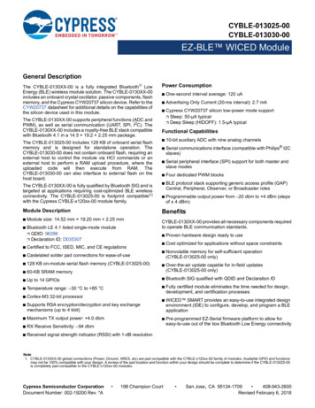
PRELIMINARYCYBLE-214015-01OverviewModule DescriptionThe CYBLE-214015-01 module is a complete module designed to be soldered to the main host board.Module Dimensions and DrawingCypress reserves the right to select components (including the appropriate BLE device) from various vendors to achieve the BLEmodule functionality. Such selections will guarantee that all height restrictions of the component area are maintained. Designs shouldbe completed with the physical dimensions shown in the mechanical drawings in Figure 1. All dimensions are in millimeters (mm).Table 1. Module Design DimensionsDimension ItemModule dimensionsSpecificationLength (X)11.00 0.15 mmWidth (Y)11.00 0.15 mmLength (X)11.00 0.15 mmWidth (Y)4.62 0.15 mmPCB thicknessHeight (H)0.80 0.10 mmShield heightHeight (H)1.00 0.10 mmAntenna location dimensionsMaximum component heightHeight (H)1.00 mm typical (shield)Total module thickness (bottom of module to highest component)Height (H)1.80 mm typicalSee Figure 1 on page 5 for the mechanical reference drawing for CYBLE-214015-01.Document Number: 002-15923 Rev. **Downloaded from Arrow.com.Page 4 of 42
PRELIMINARYCYBLE-214015-01Figure 1. Module Mechanical DrawingTop ViewSide ViewBottom ViewNote1. No metal should be located beneath or above the antenna area. Only bare PCB material should be located beneath the antenna area. For more information onrecommended host PCB layout, see Figure 3 on page 6, Figure 4 and Figure 5 on page 7, and Figure 6 and Table 3 on page 8.Document Number: 002-15923 Rev. **Downloaded from Arrow.com.Page 5 of 42
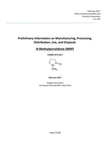
PRELIMINARYCYBLE-214015-01Pad Connection InterfaceAs shown in the bottom view of Figure 1 on page 5, the CYBLE-214015-01 connects to the host board via solder pads on the backof the module. Table 2 and Figure 2 detail the solder pad length, width, and pitch dimensions of the CYBLE-214015-01 module.Table 2. Solder Pad Connection DescriptionNameConnections Connection TypeSP32Solder PadsPad Length DimensionPad Width DimensionPad PitchPad9/Pad24: 0.74 mmAll Others: 0.79 mm0.41 mm0.66 mmFigure 2. Solder Pad Dimensions (Seen from Bottom)To maximize RF performance, the host layout should follow these recommendations:1. The ideal placement of the Cypress BLE module is in a corner of the host board with the antenna located on the edge of the hostboard. This placement minimizes the additional recommended keep-out area stated in item 2. Please refer to AN96841 for moduleplacement best practices.2. To maximize RF performance, the area immediately around the Cypress BLE module trace antenna should contain an additionalkeep-out area, where no grounding or signal traces are contained. The keep-out area applies to all layers of the host board. Therecommended dimensions of the host PCB keep-out area are shown in Figure 3 (dimensions are in mm).Figure 3. Recommended Host PCB Keep-Out Area Around the CYBLE-214015-01 Trace AntennaHost PCB Keep-Out Area Around Trace AntennaDocument Number: 002-15923 Rev. **Downloaded from Arrow.com.Page 6 of 42
PRELIMINARYCYBLE-214015-01Recommended Host PCB LayoutFigure 4 through Figure 6 and Table 3 provide details that can be used for the recommended host PCB layout pattern for theCYBLE-214015-01. Dimensions are in millimeters unless otherwise noted. Pad length of 0.99 mm (0.494 mm from center of the padon either side) shown in Figure 6 is the minimum recommended host pad length. The host PCB layout pattern can be completed usingeither Figure 4, Figure 5, or Figure 6. It is not necessary to use all figures to complete the host PCB layout pattern.Figure 4. Host Layout Pattern for CYBLE-214015-01Document Number: 002-15923 Rev. **Downloaded from Arrow.com.Figure 5. Module Pad Location from OriginPage 7 of 42
PRELIMINARYCYBLE-214015-01Table 3 provides the center location for each solder pad on the CYBLE-214015-01. All dimensions reference the to the center of thesolder pad. Refer to Figure 6 for the location of each module solder pad.Table 3. Module Solder Pad LocationFigure 6. Solder Pad Reference LocationSolder Pad(Center of Pad)Location (X,Y) fromOrign (mm)Dimension fromOrign (mils)1(0.30, 4.83)(11.81, 190.16)2(0.30, 5.49)(11.81, 216.14)3(0.30, 6.15)(11.81, 242.13)4(0.30, 6.81)(11.81, 268.11)5(0.30, 7.47)(11.81, 294.09)6(0.30, 8.13)(11.81, 320.08)7(0.30, 8.79)(11.81, 346.06)8(0.30, 9.45)(11.81, 372.05)9(0.27, 10.11)(10.63, 398.03)10(1.21, 10.70)(47.64, 421.26)11(1.87, 10.70)(73.62, 421.26)12(2.53, 10.70)(99.61, 421.26)13(3.19, 10.70)(125.59, 421.26)14(3.85, 10.70)(151.57, 421.26)15(4.51, 10.70)(177.56, 421.26)16(5.17, 10.70)(203.54, 421.26)17(5.84, 10.70)(229.92, 421.26)18(6.50, 10.70)(255.91, 421.26)19(7.16, 10.70)(281.89, 421.26)20(7.82, 10.70)(307.87, 421.26)21(8.48, 10.70)(333.86, 421.26)22(9.14, 10.70)(359.84, 421.26)23(9.80, 10.70)(385.83, 421.26)24(10.73, 10.11)(422.44, 398.03)25(10.70, 9.45)(421.26, 372.05)26(10.70, 8.79)(421.26, 346.06)27(10.70, 8.13)(421.26, 320.08)28(10.70, 7.47)(421.26, 294.09)29(10.70, 6.81)(421.26, 268.11)30(10.70, 6.15)(421.26, 242.13)31(10.70, 5.49)(421.26, 216.14)32(10.70, 4.83)(421.26, 190.16)Document Number: 002-15923 Rev. **Downloaded from Arrow.com.Page 8 of 42
PRELIMINARYCYBLE-214015-01Table 4 and Table 5 detail the solder pad connection definitions and available functions for each connection pad. Table 4 lists thesolder pads on CYBLE-214015-01, the BLE device port-pin, and denotes whether the digital function shown is available for eachsolder pad. Table 5 denotes whether the analog function shown is available for each solder pad. Each connection is configurable fora single option shown with a .Table 4. Digital Peripheral CapabilitiesPadNumberDevicePort Pin1GND[3]2P1.13P1.04P1.55P0.16P0.7UARTSPII2 CTCPWM[2]CapSenseGround Connection (SCB1 SS1) (SCB0 TX) (SCB0 MISO) (SCB0 SCL) (SCB1 TX) (SCB1 MISO) (SCB1 SCL) (SCB0 CTS) (SCB0 SCLK) (TCPWM0 N) (TCPWM0 P) (TCPWM2 N) (TCPWM0 N) (TCPWM2 N)WCO ECOOut OUT LCD SWDGPIO P2.532GND[3] (SCB0 RX) (SCB0 RX) (SCB0 TX) (SCB0 RTS)Digital Power Supply Input (1.71 to 5.5V) (SCB0 MOSI) (SCB0 SDA) (SCB0 MOSI) (SCB0 SDA) (SCB0 MISO) (SCB0 SCL) (SCB0 SS0) (SCB1 SS2) (TCPWM2 P) (TCPWM1 P) (TCPWM1 N) (TCPWM2 P) (TCPWM1 P) Radio Power Supply (1.9V to 5.5V) (SCB0 RX) (SCB1 SS3) (SCB0 SS2) (SCB0 SS3) (SCB1 RX) (SCB0 TX) (SCB1 CTS) (SCB1 TX) (SCB0 CTS) (SCB0 RTS) (SCB1 RTS) (SCB0 SDA) (TCPWM1 N) (TCPWM0 P) Analog Power Supply Input (1.71 to 5.5V) (SCB1 SDA) (TCPWM2 P) (SCB0 SCL) (TCPWM0 N) (TCPWM3 N) (SCB1 SCL) (TCPWM2 N) (TCPWM1 N)Reference Voltage Input (TCPWM1 P) (TCPWM3 P) External Reset Hardware Connection Input (SWDIO) Ground ConnectionNotes2. TCPWM stands for timer, counter, and PWM. If supported, the pad can be configured to any of these peripheral functions.3. The main board needs to connect both GND connections (Pad 1 and Pad 32) on the module to the common ground of the system.Document Number: 002-15923 Rev. **Downloaded from Arrow.com.Page 9 of 42
PRELIMINARYCYBLE-214015-01Table 5. Analog Peripheral CapabilitiesPad NumberDevice Port F27P3.228P3.629XRES30P2.431P2.532GNDDocument Number: 002-15923 Rev. **Downloaded from Arrow.com.SARMUXOPAMPLPCOMPGround Connection (CTBm1 OA0 INN) (CTBm1 OA0 INP) (CTBm1 OA1 INP)Digital Power Supply Input (1.71 to 5.5V) (CTBm1 OA1 INN) (COMP1 INP) (COMP1 INN) (CTBm1 OA0 OUT)Radio Power Supply (1.9V to 5.5V) (CTBm1 OA0 INP) (CTBm1 OA1 OUT) (CTBm1 OA0 INN) (CTBm1 OA0 OUT) (CTBm1 OA1 OUT)Analog Power Supply Input (1.71 to 5.5V)Reference Voltage Input (Optional)External Reset Hardware Connection Input (CTBm1 OA1 INN) (CTBm1 OA1 INP)Ground ConnectionPage 10 of 42
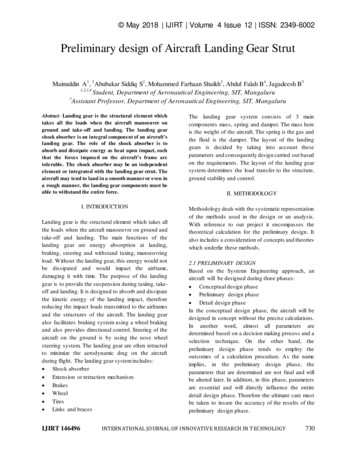
PRELIMINARYCYBLE-214015-01Power Supply Connections and Recommended External ComponentsPower ConnectionsExternal Component RecommendationThe CYBLE-214015-01 contains three power supply connections, VDD, VDDA, and VDDR. The VDD and VDDA connectionssupply power for the digital and analog device operation respectively. VDDR supplies power for the device radio.In either connection scenario, it is recommended to place anexternal ferrite bead between the supply and the moduleconnection. The ferrite bead should be positioned as close aspossible to the module pin connection.VDD and VDDA accept a supply range of 1.71 V to 5.5 V. VDDRaccepts a supply range of 1.9 V to 5.5 V. These specificationscan be found in Table 10. The maximum power supply ripple forboth power connections on the module is 100 mV, as shown inTable 8.Figure 7 details the recommended host schematic options for asingle supply scenario. The use of one or two ferrite beads willdepend on the specific application and configuration of theCYBLE-214015-01.The power supply ramp rate of VDD and VDDA must be equalto or greater than that of VDDR when the radio is used.Connection OptionsFigure 8 details the recommended host schematic for anindependent supply scenario.The recommended ferrite bead value is 330 , 100 MHz (MurataBLM21PG331SN1D).Two connection options are available for any application:1. Single supply: Connect VDD, VDDA, and VDDR to the samesupply.2. Independent supply: Power VDD, VDDA, and VDDRseparately.Figure 7. Recommended Host Schematic Options for Single Supply OptionSingle Ferrite Bead OptionDocument Number: 002-15923 Rev. **Downloaded from Arrow.com.Three Ferrite Bead OptionPage 11 of 42
PRELIMINARYCYBLE-214015-01Figure 8. Recommended Host Schematic for Independent Supply OptionDocument Number: 002-15923 Rev. **Downloaded from Arrow.com.Page 12 of 42
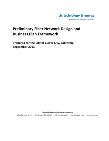
PRELIMINARYCYBLE-214015-01The CYBLE-214015-01 schematic is shown in Figure 9.Figure 9. CYBLE-214015-01 Schematic DiagramDocument Number: 002-15923 Rev. **Downloaded from Arrow.com.Page 13 of 42
PRELIMINARYCYBLE-214015-01Critical Components ListTable 6 details the critical components used in the CYBLE-214015-01 module.Table 6. Critical Component ListComponentReference DesignatorSiliconU1Description76-pin WLCSP Programmable System-on-Chip (PSoC) with BLECrystalY124.000 MHz, 10 pFCrystalY232.768 kHz, 12.5 pFAntenna DesignTable 7 details antenna used on the CYBLE-214015-01 module. The Cypress module performance improves many of thesecharacteristics. For more information, see Table 9 on page 15.Table 7. Trace Antenna SpecificationsItemFrequency RangeDescription2400 MHz–2500 MHzPeak Gain0.5 dBi typicalAverage Gain–0.5 dBi typicalReturn Loss10 dB minimumDocument Number: 002-15923 Rev. **Downloaded from Arrow.com.Page 14 of 42
PRELIMINARYCYBLE-214015-01Electrical SpecificationTable 8 details the absolute maximum electrical characteristics for the Cypress BLE module.Table 8. CYBLE-214015-01 Absolute Maximum nditionsVDDD ABSVDD, VDDA or VDDR supply relative to VSS(VSSD VSSA)–0.5–6VAbsolute maximumVCCD ABSDirect digital core voltage input relative to VSSD–0.5–1.95VAbsolute maximumVDDD RIPPLEMaximum power supply ripple for VDD, VDDA andVDDR input voltage––100mVVGPIO ABSGPIO voltage–0.5–VDD 0.5VAbsolute maximumIGPIO ABSMaximum current per GPIO–25–25mAAbsolute maximumIGPIO injectionGPIO injection current: Maximum for VIH VDDand minimum for VIL VSS–0.5–0.5mAAbsolute maximum currentinjected per pinLUPin current for latch up–200200mA–UnitDetails/Conditions3.0V supplyRipple frequency of 100 kHzto 750 kHzTable 9 details the RF characteristics for the Cypress BLE module.Table 9. CYBLE-214015-01 RF Performance 3dBm Configurable via registersettings––87–dBm Guaranteed by designsimulationRFORF output power on ANTRXSRF receive sensitivity on ANTFRModule frequency range2400–2480MHz–GPPeak gain–0.5–dBi–GAvgAverage gain––0.5–dBi–RLReturn loss––10–dB–Table 10 through Table 51 list the module level electrical characteristics for the CYBLE-214015-01. All specifications are valid for–40 C TA 85 C and TJ 100 C, except where noted. Specifications are valid for 1.71V to 5.5V, except where noted.Table 10. CYBLE-214015-01 DC SpecificationsParameterDescriptionMinVDD1Power supply input voltage (VDD VDDA VDDR)1.71VDD2Power supply input voltage unregulated (VDD VDDA VDDR)1.71VDDR1Radio supply voltage (radio on)1.9VDDR2Radio supply voltage (radio off)TypMaxUnitDetails/Conditions–5.5VWith regulator enabled1.81.89VInternally unregulatedsupply–5.5V–1.71–5.5V–1.7–mAT 25 C,VDD 3.3 VActive Mode, VDD 1.71 V to 5.5 VIDD3Execute from flash; CPU at 3 MHz–IDD4Execute from flash; CPU at 3 MHz–––mAT –40 C to 85 CIDD5Execute from flash; CPU at 6 MHz–2.5–mAT 25 C,VDD 3.3 VIDD6Execute from flash; CPU at 6 MHz–––mAT –40 C to 85 CIDD7Execute from flash; CPU at 12 MHz–4–mAT 25 C,VDD 3.3 VDocument Number: 002-15923 Rev. **Downloaded from Arrow.com.Page 15 of 42
PRELIMINARYCYBLE-214015-01Table 10. CYBLE-214015-01 DC Specifications s/ConditionsIDD8Execute from flash; CPU at 12 MHz–––mAT –40 C to 85 CIDD9Execute from flash; CPU at 24 MHz–7.1–mAT 25 C,VDD 3.3 VIDD10Execute from flash; CPU at 24 MHz–––mAT –40 C to 85 CIDD11Execute from flash; CPU at 48 MHz–13.4–mAT 25 C,VDD 3.3 VIDD12Execute from flash; CPU at 48 MHz–––mAT –40 C to 85 C–––mAT 25 C, VDD 3.3 V,SYSCLK 3 MHz–––mAT 25 C, VDD 3.3 V,SYSCLK 3 MHzT 25 C,VDD 3.3 VSleep Mode, VDD 1.71 V to 5.5 VIDD13IMO onSleep Mode, VDD and VDDR 1.9 V to 5.5 VIDD14ECO onDeep-Sleep Mode, VDD 1.71 V to 3.6 VIDD15WDT with WCO on–1.3–µAIDD16WDT with WCO on–––µAT –40 C to 85 CIDD17WDT with WCO on–––µAT 25 C,VDD 5 VIDD18WDT with WCO on–––µAT –40 C to 85 CDeep-Sleep Mode, VDD 1.71 V to 1.89 V (Regulator Bypassed)IDD19WDT with WCO on–––µAT 25 CIDD20WDT with WCO on–––µAT –40 C to 85 CHibernate Mode, VDD 1.71 V to 3.6 VIDD27GPIO and reset active–150–nAT 25 C,VDD 3.3 VIDD28GPIO and reset active–––nAT –40 C to 85 CHibernate Mode, VDD 3.6 V to 5.5 VIDD29GPIO and reset active–––nAT 25 C,VDD 5 VIDD30GPIO and reset active–––nAT –40 C to 85 CStop Mode, VDD 1.71 V to 3.6 VIDD33Stop-mode current (VDD)–20–nAT 25 C,VDD 3.3 VIDD34Stop-mode current (VDDR)–40–nAT 25 C,VDDR 3.3 VIDD35Stop-mode current (VDD)–––nAT –40 C to 85 CIDD36Stop-mode current (VDDR)–––nAT –40 C to 85 C,VDDR 1.9 V to 3.6 VStop Mode, VDD 3.6 V to 5.5 VIDD37Stop-mode current (VDD)–––nAT 25 C,VDD 5 VIDD38Stop-mode current (VDDR)–––nAT 25 C,VDDR 5 VIDD39Stop-mode current (VDD)–––nAT –40 C to 85 CIDD40Stop-mode current (VDDR)–––nAT –40 C to 85 CDocument Number: 002-15923 Rev. **Downloaded from Arrow.com.Page 16 of 42
PRELIMINARYCYBLE-214015-01Table 11. AC ails/Conditions1.71V VDD 5.5VFCPUCPU frequencyDC–48MHzTSLEEPWakeup from Sleep mode–0–µsGuaranteed by characterizationTDEEPSLEEPWakeup from Deep-Sleep mode––25µs24-MHz IMO. Guaranteed bycharacterizationTHIBERNATEWakeup from Hibernate mode––800µsGuaranteed by characterizationTSTOPWakeup from Stop mode––2msXRES wakeupMinTypMaxUnitGPIOTable 12. GPIO DC nput voltage HIGH threshold0.7 VDD––VLVTTL input, VDD 2.7 V0.7 VDD––VLVTTL input, VDD 2.7 V2.0––V––0.3 VDDVInput voltage LOW thresholdDetails/ConditionsCMOS input––CMOS inputLVTTL input, VDD 2.7 V––0.3 VDDV–LVTTL input, VDD 2.7 V––0.8V–Output voltage HIGH levelVDD – 0.6––VIOH 4 mA at 3.3-V VDDOutput voltage HIGH levelVDD – 0.5––VIOH 1 mA at 1.8-V VDDOutput voltage LOW level––0.6VIOL 8 mA at 3.3-V VDDOutput voltage LOW level––0.6VIOL 4 mA at 1.8-V VDDIOL 3 mA at 3.3-V VDD––0.4VRPULLUPOutput voltage LOW levelPull-up resistor3.55.68.5k RPULLDOWNPull-down resistor3.55.68.5k IILInput leakage current (absolute value)––2nAIIL CTBMInput leakage on CTBm input pins––4nA–CINInput capacitance––7pF–––25 C, VDD 3.3 VVHYSTTLInput hysteresis LVTTL2540–mVVHYSCMOSInput hysteresis CMOS0.05 VDD––1–IDIODECurrent through protection diode toVDD/VSS––100µA–ITOT GPIOMaximum total source or sink chipcurrent––200mA–VDD 2.7 VNote4. VIH must not exceed VDD 0.2 V.Document Number: 002-15923 Rev. **Downloaded from Arrow.com.Page 17 of 42
PRELIMINARYCYBLE-214015-01Table 13. GPIO AC SpecificationsParameterTRISEFDescriptionRise time in Fast-Strong modeMin2Typ–Max12TFALLFFall time in Fast-Strong mode2–12TRISESRise time in Slow-Strong mode10–60ns3.3-V VDDD, CLOAD 25 pFTFALLSFall time in Slow-Strong mode10–60ns3.3-V VDDD, CLOAD 25 pFFGPIOUT1GPIO Fout; 3.3 V VDD 5.5 VFast-Strong mode––33MHz 90/10%, 25 pF load, 60/40 duty cycleFGPIOUT2GPIO Fout; 1.7 V VDD 3.3 VFast-Strong modeGPIO Fout; 3.3 V VDD 5.5 VSlow-Strong mode––16.7MHz 90/10%, 25 pF load, 60/40 duty cycle––7MHz 90/10%, 25 pF load, 60/40 duty cycleFGPIOUT4GPIO Fout; 1.7 V VDD 3.3 VSlow-Strong mode––3.5MHz 90/10%, 25 pF load, 60/40 duty cycleFGPIOINGPIO input operating frequency1.71 V VDD 5.5 V––48MHz 90/10% VIOFGPIOUT3UnitDetails/Conditionsns 3.3-V VDDD, CLOAD 25 pFns3.3-V VDDD, CLOAD 25 pFXRESTable 14. XRES DC SpecificationsParameterVIHDescriptionInput voltage HIGH thresholdVILInput voltage LOW thresholdRPULLUPPull-up resistorMinTyp0.7 VDDD–Max–UnitDetails/ConditionsV CMOS input––0.3 VDDDV3.55.68.5k CMOS input–CINInput capacitance–3–pF–VHYSXRESInput voltage hysteresis–100–mV–IDIODECurrent through protection diode ails/ConditionsTable 15. XRES AC SpecificationsParameterTRESETWIDTHDescriptionReset pulse width–Analog PeripheralsOpampTable 16. Opamp ails/Conditions1300µA–IDD (Opamp Block Current. VDD 1.8 V. No Load)IDD HIPower high–1000IDD MEDPower medium–500–µA–IDD LOWPower low–250350µA–6––MHz–GBW (Load 20 pF, 0.1 mA. VDDA 2.7 V)GBW HIPower highGBW MEDPower medium4––MHz–GBW LOPower low–1–MHz–10––mA–IOUT MAX (VDDA 2.7 V, 500 mV from Rail)IOUT MAX HIPower highDocument Number: 002-15923 Rev. **Downloaded from Arrow.com.Page 18 of 42
PRELIMINARYCYBLE-214015-01Table 16. Opamp Specifications s/ConditionsIOUT MAX MIDPower medium10––mA–IOUT MAX LOPower low–5–mA–IOUT (VDDA 1.71 V, 500 mV from Rail)IOUT MAX HIPower high4––mA–IOUT MAX MIDPower medium4––mA–IOUT MAX LOPower low–2–mA–VINCharge pump on, VDDA 2.7 V–0.05–VDDA – 0.2V–VCMCharge pump on, VDDA 2.7 V–0.05–VDDA – 0.2V–VOUT (VDDA 2.7 V)VOUT 1Power high, ILOAD 10 mA0.5–VDDA – 0.5V–VOUT 2Power high, ILOAD 1 mA0.2–VDDA – 0.2V–VOUT 3Power medium, ILOAD 1 mA0.2–VDDA – 0.2V–VOUT 4Power low, ILOAD 0.1 mA0.2–VDDA – 0.2VVOS TROffset voltage, trimmed1 0.51mVHigh modeVOS TROffset voltage, trimmed– 1–mVMedium modeVOS TROffset voltage, trimmed– 2–mVLow mode–VOS DR TROffset voltage drift, trimmed–10 310µV/CHigh modeVOS DR TROffset voltage drift, trimmed– 10–µV/CMedium modeVOS DR TROffset voltage drift, trimmed– 10–µV/CLow modeCMRRDC6570–dBVDDD 3.6 V,High-power modePSRRAt 1 kHz, 100-mV ripple7085–dBVDDD 3.6 VVN1Input referred, 1 Hz–1 GHz, power high–94–µVrmsVN2Input referred, 1 kHz, power high–72–nV/rtHz–VN3Input referred, 10 kHz, power high–28–nV/rtHz–VN4Input referred, 100 kHz, power high–15–nV/rtHz–CLOADStable up to maximum load. Performancespecs at 50 pF––125pFSlew rateCloa
The Cypress CYBLE-214015-01 is a fully certified and qualified module supporting Bluetooth Low Energy (BLE) wireless communication. The CYBLE-214015-01 is a turnkey solution and includes onboard crystal osc illators, trace antenna, passive components, and the Cypress PSoC 4 BLE. Refer to the