Transcription
May 2018 IJIRT Volume 4 Issue 12 ISSN: 2349-6002Preliminary design of Aircraft Landing Gear StrutMainuddin A1 , 2 Abubakar Siddiq S2 , Mohammed Farhaan Shaikh3 , Abdul Falah B4 , Jagadeesh B51,2,3,4Student, Department of Aeronautical Engineering, SIT, Mangaluru5Assistant Professor, Department of Aeronautical Engineering, SIT, MangaluruAbstract- Landing gear is the structural element whichtakes all the loads when the aircraft manoeuvre onground and take-off and landing. The landing gearshock absorber is an integral component of an aircraft’slanding gear. The role of the shock absorber is toabsorb and dissipate energy as heat upon impact, suchthat the forces imposed on the aircraft’s frame aretolerable. The shock absorber may be an independentelement or integrated with the landing gear strut. Theaircraft may tend to land in a smooth manner or even ina rough manner, the landing gear components must beable to withstand the entire force.The landing gear system consists of 3 maincomponents mass, spring and damper. The mass hereis the weight of the aircraft. The spring is the gas andthe fluid is the damper. The layout of the landinggears is decided by taking into account theseparameters and consequently design carried out basedon the requirements. The layout of the landing gearsystem determines the load transfer to the structure,ground stability and control.I. INTRODUCTIONMethodology deals with the systematic representationof the methods used in the design or an analysis.With reference to our project it encompasses thetheoretical calculation for the preliminary design. Italso includes a consideration of concepts and theorieswhich underlie these methods.Landing gear is the structural element which takes allthe loads when the aircraft manoeuvre on ground andtake-off and landing. The main functions of thelanding gear are energy absorption at landing,braking, steering and withstand taxing, manoeuvringload. Without the landing gear, this energy would notbe dissipated and would impact the airframe,damaging it with time. The purpose of the landinggear is to provide the suspension during taxiing, takeoff and landing. It is designed to absorb and dissipatethe kinetic energy of the landing impact, thereforereducing the impact loads transmitted to the airframesand the structures of the aircraft. The landing gearalso facilitates braking system using a wheel brakingand also provides directional control. Steering of theaircraft on the ground is by using the nose wheelsteering system. The landing gear are often retractedto minimize the aerodynamic drag on the aircraftduring flight. The landing gear system includes: Shock absorber Extension or retraction mechanism Brakes Wheel Tires Links and bracesIJIRT 146496II. METHODOLOGY2.1 PRELIMINARY DESIGNBased on the Systems Engineering approach, anaircraft will be designed during three phases: Conceptual design phase Preliminary design phase Detail design phaseIn the conceptual design phase, the aircraft will bedesigned in concept without the precise calculations.In another word, almost all parameters aredetermined based on a decision making process and aselection technique. On the other hand, thepreliminary design phase tends to employ theoutcomes of a calculation procedure. As the nameimplies, in the preliminary design phase, theparameters that are determined are not final and willbe altered later. In addition, in this phase, parametersare essential and will directly influence the entiredetail design phase. Therefore the ultimate care mustbe taken to insure the accuracy of the results of thepreliminary design phase.INTERNATIONAL JO URNAL OF INNOVATIVE RESEARCH IN TECHNOLOGY730
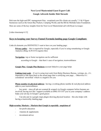
May 2018 IJIRT Volume 4 Issue 12 ISSN: 2349-6002The preliminary design phase is performed in threesteps: Estimate aircraft maximu m take-off weight Determine fuselage length and fuselage area Determine wing area2.2 MAXIMUM TAKE-OFF WEIGHT ESTIMATIONThe general technique to estimate the maximum takeoff weight is as follows: the aircraft weight is brokeninto several parts. Some parts are determined basedon statistics, but some are calculated fromperformance equations.Maximum take-off weight (W TO ) is broken into fourelements. Payload weight (W P L ) Crew weight (W C) Fuel weight (W F) Empty weight (W E )The payload weight and crew weight are almostknown and determined from the given data and arenot depending on the aircraft take-off weight. On theother hand, the empty weight and fuel weight areboth functions of the maximum take-off weight.Hence, to simplify the calculation, both the fuelweight and empty weight are expressed as fractionsof the maximu m take-off weight. Hence:()()Thus:() ()Problem statement:To design a conventional civil transport aircraft thatcan carry 120 passengers plus their luggage. Theaircraft must be able to fly with a cruise speed ofMach number 0.8, and have a range of 6500 km. Theaircraft is equipped with two high bypass ratioturbofan engines and is cruising at 35,000 ft altitude.Solution:-Fig. 3.1. Mission profile for the transport aircraftStage 2: Weight of flight crew and attendantsThe number of flight attendants is regulated by FARPart 125, Section 125.269: For airplanes having morethan 100 passengers, two flight attendants plus oneadditional flight attendant for each unit of 50passengers above 100 passengers.Since there are 120 passengers, number of flightattendants must be 3.Flight crew members are assumed to have a weight of200 lbs. On the other hand, flight attendant’s weightis 140 lb be allocated for a flight attendant whose sexin unknown. Thus, the total weight of flight crewmembers and flight attendants is:Stage 3: The weight of payloadsThe payload for a passenger aircraft primarilyincludes passengers and their luggage and baggage.Passengers could be a combination of adult males,adult females, children, and infants. To observe thereality and to be on the safe side, an average weightof 180 lb id selected. This weight includes theallowance for personal items and carry-on bags. Onthe other hand, 100 lbs of luggage is considered foreach passenger. So the total payload would be:Stage 4: Fuel weight ratios for the segments of taxi,take-off, climb, descent, approach and landingTaxi, take-off:Climb:Stage 1: The aircraft is stated to be civil transport andto carry 120 passengers. Hence, the aircraft mustfollow FAR Part 25. Therefore, all selections must bebased on Federal Aviation Regulations. The regularmission profile for this aircraft cons ists of taxi andtake-off, climb, cruise, descent, and landing.IJIRT 146496Descent:Approach and landing:Stage 5: Fuel weight ratio for the segment of rangeINTERNATIONAL JO URNAL OF INNOVATIVE RESEARCH IN TECHNOLOGY731
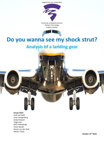
May 2018 IJIRT Volume 4 Issue 12 ISSN: 2349-6002The aircraft has jet (turbofan) engine, so equation 3.7must be employed. In this flight mission, cruise is thethird phase of flight. Where range (R) is 9500 km, C is 0.4 lb/hr/lb or0.4/3600 1/sec, and (L/D)max is 17 . The aircraftspeed (V) would be the Mach number times the speedof sound.Where the speed of sound at 35,000ft altitude is296.6 m/sec. Thus,Stage 6: Overall fuel weight ratioBy using equationSubstituting the value in equation 3.6()Thus, the aircraft maximu m take-off weight is:2.4 SHOCK ABSORBER DESIGNThe landing gear shock absorber is an integralcomponent of an aircraft’s landing gear. The role ofthe shock absorber is to absorb and dissipate energyupon impact, such that the forces imposed on theaircraft’s frame are tolerable. The majority of landinggear shock struts are comprised of a piston andcylinder, pressurized by compressed nitrogen, usinghydraulic fluid as the damping medium. Thehydraulic chamber is normally separated from the airchamber by an orifice.Stage 7: SubstitutionSubstituting the values in equation 3.3()()(())Stage 8: empty weight ratioThe empty weight ratio is established by usingequation 3.8, where the coefficients a and b are,Thus:Step 9: Solve the equation analyticallyTable 3.1 Trial and error technique to determinemaximu m take-off weight of the aircraftIJIRT 146496Fig 3.2. Oleo-pneumatic shock absorberIII. RESULTS AND DISCUSSIONINTERNATIONAL JO URNAL OF INNOVATIVE RESEARCH IN TECHNOLOGY732
May 2018 IJIRT Volume 4 Issue 12 ISSN: 2349-6002The calculations were made to estimate the maximumtake-off weight of an aircraft depending upon thenumber of pilots and crew, fuel, and payloads(passengers, loads, luggage, and cargo). According tothe methodology specified in the previous chapter,the following results can be obtained to design theshock strut.3.1 WHEEL LOADINGThe first step in calculating the load on the wheel isto calculate the design aircraft landing weight. For atransport-type aircraft the landing load factor variesfrom 0.7 to 1.5 of the calculated aircraft weight.Aircraft weight 1,82,008 lbDesign aircraft weight 1.51,82,008 2,73,012lbWeight on nose landing gear is taken as 12% of W TONLG 32761 lbWeight on main landing gear is taken as 88% of W TOMLG 2,40,250 lbSince there are two main landing gears, load on eachisTherefore, load on each main landing gear strut 1,20,125 lbAccording to the configuration selected, each MLGwill have two tires. Therefore, load on each tire is60,062.5 lb.Therefore, tire selected is the Michelin Air Bias typeVII Type III 50 x 20.0 – 20 (data taken fromMichelin Tire Data Hand Book).Where,50 Maximum diameter when fully inflated, i.e., 50inches20.0 Width of the tire when fully loaded i.e., 20inches20 Rim diameter i.e., 20 inches3.2 STRUT PISTON DIAMETER:Strut is pressurised with nitrogen at 1500 psi, hencethe piston area is given byThe touchdown kinetic energy or the kinetic energyin the vertical direction at touchdown can beapproximated from the equation,where W is the aircraft weight, V is the sink speed, gis the gravitational acceleration, L is the wing lift,and St is the tire deflection, SS is shock absorberstroke. The kinetic energy capacity of the shockabsorber and tire must be equal to the total energy.Thus,whereandare the shock absorber and tireabsorber efficiency factors, respectively. It isgenerally assumed to be 0.8 and the latter 0.47 for anoleo-pneumatic strut. N is the landing gear loadfactor.if we assume that the potential energy term isnegligible and if the lift generated is approximatelyequal to the weight of the aircraft during landing,then the stroke length is determined by,* Static load radius SLR()()()Then,[] To maintain an adequate safety margin, an extra oneinch of stroke is usually added to the calculatedstroke.Therefore,The displacement volume of the shock absorber strutis given by,Area Diameter of the piston is given by,Area of piston Then, diameter d 3.3 PISTON STROKEIJIRT 146496where S is the stroke length and A is the area of thepiston. 3.4 STROKE VOLUMEThe volume of the gas and oil in the shock strut isconsidered as the stroke volume. Standard notationINTERNATIONAL JO URNAL OF INNOVATIVE RESEARCH IN TECHNOLOGY733
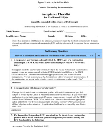
May 2018 IJIRT Volume 4 Issue 12 ISSN: 2349-6002for shock strut volume is used where V1 to denotesthe fully extended position, V2 to denotes the staticposition, and V3 to denotes the compressed position.Generally, the fully extended position is when thereis on load acting on the strut, static position is duringtaxiing and the compressed position is when theaircraft touches down during the landing. Tomaintain an tolerable safety margin during heavy orsemi-crash landing, shock absorbers are designedsuch that the piston is not fully bottomed even at thecompressed position. The safety margin of 10% ofthe displacement is maintained. The static position isabout 16 percent of the total stroke [20].Fig 4.2 PositionFrom the stroke (S) the pressure during isothermalcompression is calculated,The pressure at stroke (S) calculated using the aboveequation, where P1 375 psi, is the stroke V1 is thefully extended volume and A is area of the piston.Therefore, the isothermal pressure of the gas isapproximately 1500 psi during extended and staticpositions.The pressure inside the shock absorber cylinderduring compressed position is expressed by thepolytropic equation [20].* * where n is constant and is given as 1.35 or 1.1, this isused when the gas and oil are separated and they aremixed during compression. The pressure inside thecylinder should be maintained less than 6,000 psi toprevent seal leakage during the compression.[]When,of the shock strutFirst, the strut-compressed case is considered.The piston is not fully bottomed at the compressedposition, i.e., V3 0. The reserve air volume of 10%of the displacement is maintained.Thus, the volume when the strut is fully extended isgiven by,Static position is the16% of the total stroke volumeV13.5 PRESSUREThe pressure inside the shock absorber cylinderduring extended and static positions are defined bythe isothermal compression equation,IJIRT 146496Therefore, the piston can be displaced upto amaximu m of 0.68 inch from the static position.3.6 STRUT WALL THICKNESSThe assumed material of the strut is Maraging steelwith an yield strength of 1800 MPa for a maximumpressure to be handled of 6000 psi.The thickness of the strut is given by,Thickness of Strut Wall 3.94 mm.INTERNATIONAL JO URNAL OF INNOVATIVE RESEARCH IN TECHNOLOGY734
May 2018 IJIRT Volume 4 Issue 12 ISSN: 2349-6002IV. CONCLUSIONIn this work the preliminary design of a 120-seaterpassenger aircraft. All the parameters like weight,fuselage length, wing area, fuel, etc, are calculated.These calculations are based on preliminary design ofaircraft and they need to be iterated again and againas the data of the aircraft gets frozen.When shocks occur caused by hard landings and bytaxiing over rough surfaces they are absorbedefficiently by oleo-pneumatic shock absorbers andtyres. Thus, the most effective type of shock absorbersystem is oleo-pneumatic shock strut.The future holds many new developments in landinggear shock absorb
Preliminary design of Aircraft Landing Gear Strut Mainuddin A1, 2Abubakar Siddiq S2, Mohammed Farhaan Shaikh3, Abdul Falah B4, . The spring is the gas and the fluid is the damper. The layout of the landing gears is decided by taking into account these parameters and consequently design carried out based on the requirements. The layout of the landing gear system determines the load transfer .