Transcription
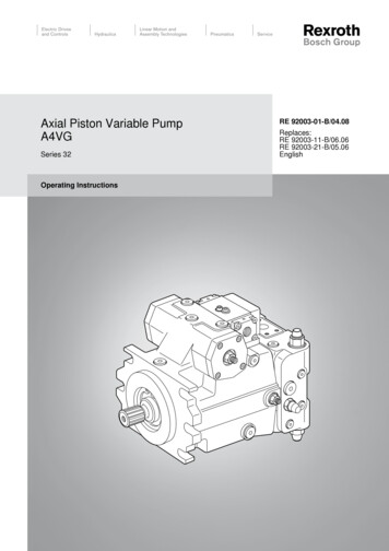
Axial Piston Variable PumpA4VGSeries 32Operating InstructionsRE 92003-01-B/04.08Replaces:RE 92003-11-B/06.06RE 92003-21-B/05.06English
The data specified above only serve to describethe product. No statements concerning a certaincondition or suitability for a certain application canbe derived from our information. The informationgiven does not release the user from the obligationof own judgment and verification. It must beremembered that our products are subject to anatural process of wear and aging. This document, as well as the data,specifications and other information set forth in it,are the exclusive property of Bosch Rexroth AG.It may not be reproduced or given to third partieswithout its consent.An example configuration is shown on the titlepage. The delivered product may, therefore, differfrom the product which is pictured.The original operating instructions were created inthe German language.
RE 92003-01-B/04.08 A4VG Series 32Bosch Rexroth AG3/60ContentsContents1About this document.41.1 Related documents.41.2 Abbreviations used.52General safety instructions.62.1 Intended use.62.2 Improper use.62.3 Personnel qualifications.62.4 Safety instructions in this document.72.5 Adhere to the following instructions.72.6 Operator's obligations.93Delivery contents.104Product description.114.1 Performance description.114.2 Device description.114.3 Bypass function.194.4 Product identification.235Transport and storage.245.1 Transporting the axial piston unit.245.2 Storing the axial piston unit.256Assembly.276.1 Unpacking.276.2 Installation conditions.276.3 Installation position.296.4 Assembling the axial piston unit.337Commissioning.437.1 First commissioning.447.2 Recommissioning after downtime.467.3 Running-in phase.468Operation.479Maintenance and repair.489.1 Cleaning and care.489.2 Inspection.489.3 Maintenance.499.4 Repair.499.5 Spare parts.4910 Decommissioning.5011 Disassembly and replacement.5011.1 Required tools.5011.2 Preparing for disassembly.5011.3 Disassembling the axial piston unit.5011.4 Preparing the components for storage or further use. 5112 Disposal. 5212.1 Environmental protection.5213 Extension and conversion.5214 Troubleshooting.5314.1 How to proceed for troubleshooting.5314.2 Malfunction table.5415 Technical data.5616 Appendix. 5616.1 Address directory .5617 Index.57
4/60Bosch Rexroth AGA4VG Series 32 RE 92003-01-B/04.08About this document1 About this documentThese instructions contain important information on the safe and appropriateassembly, transport, commissioning, maintenance, disassembly and simpletroubleshooting of the A4VG series 32 axial piston variable pump.ff Read these instructions completely, especially chapter "2 Generalsafety instructions" on page 6, before working with the A4VGaxial piston variable pump.1.1Related documentsThe A4VG axial piston variable pump is a system component. Also observe theinstructions for the other system components.Further information on the A4VG axial piston variable pump, its installation andoperation can be found in the Rexroth documents listed in the following table.Table 1: Related documentsRelated documentsContentsOrder confirmationContains the preset technical data of your A4VGaxial piston variable pump.Installation drawingContains the outer dimensions, all connectionsand the hydraulic circuit diagram for your A4VGaxial piston variable pump.Data sheet RE 92003Contains the permissible technical data for the A4VGseries 32 axial piston variable pump.Data sheet RE 90220Describes the requirements for a mineral-oil based hydraulicfluid for operation with Rexroth axial piston units and assistsyou in selecting a hydraulic fluid for your system.Data sheet RE 90221Describes the requirements for an environmentally acceptablehydraulic fluid for operation with Rexroth axial piston units andassists you in selecting a hydraulic fluid for your system.Data sheet RE 90223Contains additional information on the use of Rexroth axialpiston units with HF hydraulic fluids.Data sheetRE 90300-03-BContains additional information on the use of Rexroth axialpiston units at low temperatures.Also observe the generally applicable, legal or otherwise binding regulations ofthe European and national legislation and the rules for the prevention of accidentsand for environmental protection applicable in your country.
RE 92003-01-B/04.08 A4VG Series 32Bosch Rexroth AG5/60About this document1.2Abbreviations usedAs umbrella term for "A4VG axial piston variable pump", the designation "axialpiston unit" will be used in the following.Table 2: AbbreviationsAbbreviationMeaningA4VGAxial piston variable pump, closed circuitsDAAutomatic control, hydraulic, speed relatedEPProportional control, electricHDProportional control, hydraulic, pilot-pressure relatedHWProportional control, hydraulic, mechanical servoRERexroth document in the English language
6/60Bosch Rexroth AGA4VG Series 32 RE 92003-01-B/04.08General safety instructions2 General safety instructionsThe axial piston unit has been manufactured according to the accepted rules ofcurrent technology. There is, however, still a danger of personal injury or damageto equipment if the following general safety instructions and the warnings beforethe steps contained in these instructions are not complied with.ff Read these instructions completely and thoroughly before working with theaxial piston unit.ff Keep these instructions in a location where they are accessible to all users atall times.ff Always include the operating instructions when you pass the axial piston uniton to third parties.2.1Intended useAxial piston units are components in terms of the EU machine directive 98/37/EC(sub units). Axial piston units are not ready-to-use machines for the purpose of theEU machine directive. The product/component is exclusively intended for beingintegrated in a machine or system or for being assembled with other componentsto form a machine or system. The product may only be commissioned after it hasbeen installed in the machine/system for which it is intended.The axial piston variable pump generates, controls and regulates a hydraulic-fluidflow. It is approved for use as a hydraulic pump in hydrostatic drives in closedcircuits.ff Observe the technical data, operating conditions and performance limits asspecified in the data sheet and order confirmation.The axial piston unit is not designed for private use.Intended use includes having read and understood these instructions, especiallychapter "2 General safety instructions".2.2Improper useThe axial piston unit may not be used in explosive environments.In addition, any use of the axial piston unit other than described in chapter"2.1 Intended use" is considered to be improper.2.3Personnel qualificationsAssembly, commissioning and operation, disassembly, maintenance andrepair require basic mechanical, hydraulic and electrical knowledge, as well asknowledge of the appropriate technical terms. For transporting and handling theproduct, additional knowledge is necessary with regard to working with a craneand the corresponding attachment equipment. In order to ensure operating safety,these activities may therefore only be carried out by qualified personnel or aninstructed person under the direction and supervision of qualified personnel.
RE 92003-01-B/04.08 A4VG Series 32Bosch Rexroth AG7/60General safety instructionsQualified personnel are those who can recognize possible hazards and institutethe appropriate safety measures due to their professional training, knowledge,and experience, as well as their understanding of the relevant conditionspertaining to the work to be done. Qualified personnel must observe the rulesrelevant to the subject area.2.4Safety instructions in this documentIn this manual, there are safety instructions before the steps whenever there is adanger of personal injury or damage to equipment. The measures described toavoid these hazards must be observed.Safety instructions are set out as follows:Signal word!Type of danger!Consequencesff PrecautionsSafety sign: (warning triangle): draws attention to the dangerSignal word: identifies the degree of the dangerType of danger: identifies the type or source of the dangerConsequences: describes what occurs if the safety instructions are notcomplied with Precautions: states how the danger can be avoided. The signal words have the following meaning:Signal wordDanger!ApplicationIndicates an imminently hazardous situation which, if notavoided, will certainly result in death or serious injury.Warning!Indicates a potentially hazardous situation which, if notavoided, could result in death or serious injury.Caution!Indicates a potentially hazardous situation which, if notavoided, could result in minor or moderate injury or damage toequipment.If this information is disregarded, the operating proceduremay be impaired.2.5General instructionsAdhere to the following instructions Observe the regulations for accident prevention and environmental protectionfor the country where the product is used and at the workplace. Only use Rexroth axial piston units in good technical order and condition.–– Inspect the product for obvious defects. Do not modify or retrofit the axial piston unit. Only use the product within the performance range provided in the technicaldata. Persons who assemble, commission, operate, disassemble or maintain Rexrothproducts must not consume any alcohol, drugs or pharmaceuticals that mayaffect their ability to respond.
8/60Bosch Rexroth AGA4VG Series 32 RE 92003-01-B/04.08General safety instructions The warranty only applies to the delivered configuration. The warranty is rendered void if the product is incorrectly assembled,commissioned or operated, as well as if not used as intended and/or handledimproperly. Do not expose the product to any mechanical loads under any circumstances.Never use the product as a handle or step. Do not place/lay any objects on it. The noise emission of axial piston units depends on speed, operating pressureand installation conditions. The sound pressure level may rise above 70 dBAduring normal operating conditions. This can cause hearing damage.–– Always wear hearing protection while working in the vicinity of the operatingaxial piston unit. The axial piston unit heats up considerably during operation. The solenoids ofthe axial piston unit get so hot during operation that you may burn yourself:–– Allow the axial piston unit to cool down sufficiently before touching it.–– Wear heat-resistant protective clothing, e.g. gloves.During transport Make certain that the lifting gear has adequate lifting capacity. The weight canbe found in chapter "5 Transport and storage".During assembly Before assembling, make sure that all fluids have been completely removedfrom the axial piston unit to prevent mixing with the hydraulic fluid used in thesystem. Make sure the relevant system component is not under pressure or voltagebefore assembling the product or when connecting and disconnecting plugs.Protect the system against being switched on. Lay cables and lines so that they cannot be damaged and no one can trip overthem. Before commissioning, make sure that all hydraulic connections are tight andthat all the connection seals and plugs are installed correctly to ensure that theyare leakproof and fluids and contaminants are prevented from penetrating theproduct. When assembling, provide for absolute cleanliness in order to preventcontaminants such as welding beads or metal cuttings from getting into thehydraulic lines and causing product wear or malfunctions.During commissioning Ensure that all electrical and hydraulic connections and ports are occupied orplugged. Only commission a completely installed product.During cleaning Plug all openings with the appropriate protective equipment in order to preventdetergents from penetrating the system. Never use solvents or aggressive detergents. Use only water and, if necessary,a mild detergent to clean the axial piston unit. Do not point a high-pressure cleaner at sensitive components such as, e.g.shaft seal ring, electrical connections and electrical components.During maintenance and repair Perform the prescribed maintenance work at the intervals specified in theoperating instructions (see chapter "9.3 Maintenance"). Make sure that no lines, connections or components are disconnected as longas the system is under pressure. Protect the system against being switched on.During disposal Dispose of the product and the hydraulic fluid in accordance with the currentlyapplicable national regulations in your country.
RE 92003-01-B/04.08 A4VG Series 32Bosch Rexroth AG9/60General safety instructions2.6Operator's obligationsThe operator of the axial piston unit from Rexroth must provide personnel trainingon a regular basis regarding the following subjects: Observation and use of the operating instructions and the legal regulations. Intended use and operation of the axial piston unit. Observation of the instructions from the factory security offices and of the workinstructions from the operator.Rexroth offers training support for special fields.You can find an overview of the training contents on the Internet at:http://www.boschrexroth.de/didactic.
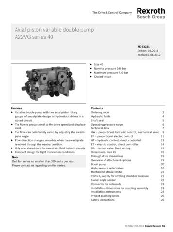
10/60Bosch Rexroth AGA4VG Series 32 RE 92003-01-B/04.08Delivery contents3 Delivery contents3243123Fig. 1: Axial piston unitIncluded in the delivery contents are: 1 Axial piston unitThe following parts are also assembled on delivery: Transport protection for drive shaft end (1).Protective covers (2).Plastic plugs / locking screws (3).Flange cover and fixing screws (4) (optional for versions with through drive).
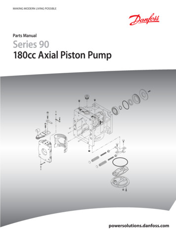
RE 92003-01-B/04.08 A4VG Series 32Bosch Rexroth AG11/60Product description4 Product description4.1Performance descriptionThe axial piston variable pump generates, controls and regulates a hydraulic-fluidflow. It is designed for mobile applications such as construction machinery.Refer to the data sheet and order confirmation for the technical data, operatingconditions and operating limits of the axial piston unit.4.2Device descriptionThe A4VG is an axial piston variable pump with swashplate design for hydrostaticdrives in closed circuits. Flow is proportional to drive speed and displacement.The flow can be steplessly changed by controlling the swashplate (11).Closed circuitA hydraulic system is considered to be closed if the hydraulic fluid which flowsback from the consumer is directed directly back to the pump. Here, there isa high-pressure side and a low-pressure side depending on the load direction(output torque on the consumer).4.2.1 Assembly of the axial piston unit435267112101198Fig. 2: Assembly of the A4VG series 321Drive shaft5Control plate10 Piston2Retaining plate6Low-pressure side11 Slipper pad3Stroke piston7Auxiliary pump12 Swashplate4Controller(using the EP as anexample here)8High-pressure side9CylinderFor axial piston units with swashplate design, the pistons (10) are arranged axiallywith respect to the drive shaft (1). They are guided in the rotating cylinder (9) andsupport themselves with the slipper pads (11) on the non-rotating swashplate(12). The drive shaft (1) and cylinder (9) are connected to one another by meansof gearing.
12/60Bosch Rexroth AGA4VG Series 32 RE 92003-01-B/04.08Product description4.2.2 Functional descriptionPumpPressure cut-offTorque is applied to the drive shaft (1) by an engine. The cylinder (9) turns withthe drive shaft, turning with it the pistons (10). On each rotation, the pistonsperform a stroke movement which is defined by the pitch of the swashplate (12).The slipper pads (11) are held on and guided along the glide surface of theswashplate by the retaining plate (2). During a rotation, each piston moves overthe bottom and top dead centers back to its initial position. During this action, thefluid volume defined by the piston surface and the stroke is fed in or removedthrough the two control slits in the control plate (5). On the low-pressure side, (6)fluid flows into the enlarging piston chamber – in a closed circuit this is supportedby the return and boost pressures. At the same time, on the high-pressureside (8) the fluid is pushed out of the cylinder chamber into the hydraulic systemby the pistons.The operating pressure is limited by the pressure cut-off.The pressure cut-off corresponds to a pressure regulator which reduces the pumpcapacity once the set specified pressure value is reached so that the set pressureis maintained but not exceeded.High-pressure safeguardingThe pressure spikes which occur during very rapid swiveling operations as well asthe maximum pressure are safeguarded by the superordinate high-pressure reliefvalves. These valves open if the set value is exceeded, thereby depressurizingthe low-pressure side. The fluid quantity remains constant in the closed circuit.The leakage at the pump and motor is replaced by the auxiliary pump (7).Auxiliary pumpThe auxiliary pump continuously supplies a sufficient volume of fluid (boostvolume) from a small tank to the low-pressure side of the closed circuit via acheck valve to replenish the internal leakage of the variable pump and consumer.Neutral valve(optional)The optional neutral valve interrupts the active control pressure and joins the twopositioning chambers for pressure equalization. The springs in the positioningchambers move the stroke piston (3) towards the middle position (neutralposition). The reset function is influenced by the current operating pressure andthe speed.Switching off the control pressure and a bypass function for the two positioningchambers does not ensure that the pump moves to the middle position (neutralposition).Use an appropriate emergency-off device to ensure that the drive can be broughtto a safe position at any time. The device or system operator is responsible for theinstallation of a proper emergency-off device.The following warning notice applies to all axial piston units with the HD and EPcontrol units:Caution!The spring return in the control unit is not a security device.The slide valve of the control unit can be blocked in an undefined position byinternal contamination (impure hydraulic fluid, abrasion or residual contaminationfrom system components). As a result, the axial piston unit can no longer supplythe flow specified by the operator.ff Properly install an emergency-off function to ensure that the driven consumercan be brought to a safe position (e.g. immediate stop).ff Maintain the specified cleanliness level 20/18/15 ( 90 C) or 19/17/14 inaccordance with ISO 4406.
RE 92003-01-B/04.08 A4VG Series 32Bosch Rexroth AG13/60Product descriptionControlThe swivel angle of the swashplate (12) is infinitely variable. By changing theswivel angle, the piston stroke and, therefore, the displacement change. Theswivel angle is controlled hydraulically via the stroke piston (3). The swashplate ismounted for easy motion in swivel bearings and the neutral position springcentered. Increasing the swivel angle increases the displacement; reducing theangle results in a corresponding reduction in displacement.If the swashplate is not swiveled out, the displacement is equal to zero. Variouscontrollers are available depending on requirements.Additional information on the control devices, such as the circuit diagram orcharacteristics, can be found in technical data sheet RE 92003.
14/60Bosch Rexroth AGA4VG Series 32 RE 92003-01-B/04.08Product description4.2.3 Control unitsNV – version without control unitThe
HW Proportional control, hydraulic, mechanical servo RE Rexroth document in the English language. 6/60 Bosch Rexroth AG A4VG Series 32 RE 92003-01-B/04.08 General safety instructions . In this manual, there are safety instructions before the steps whenever there is a danger of personal injury or damage to equipment. The measures described to