Transcription
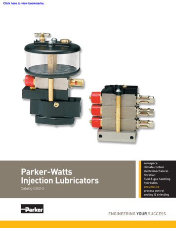
Click here to view bookmarks.Parker-WattsInjection LubricatorsCatalog 0302-2(3-18-2013)aerospaceclimate controlelectromechanicalfiltrationfluid & gas handlinghydraulicspneumaticsprocess controlsealing & shielding
Injection LubricatorsCatalog 0302-2Warning, Offer of Sale! WARNINGFAILURE, IMPROPER SELECTION OR IMPROPER USE OF THE PRODUCTS AND/OR SYSTEMS DESCRIBED HEREINOR RELATED ITEMS CAN CAUSE DEATH, PERSONAL INJURY AND PROPERTY DAMAGE.This document and other information from The Company, its subsidiaries and authorized distributors provide product and/orsystem options for further investigation by users having technical expertise. It is important that you analyze all aspectsof your application, and review the information concerning the product or system in the current product catalog. Due tothe variety of operating conditions and applications for these products or systems, the user, through its own analysis andtesting, is solely responsible for making the final selection of the products and systems and assuring that all performance,safety and warning requirements of the application are met.The products described herein, including without limitation, product features, specifications, designs, availability and pricing,are subject to change by The Company and its subsidiaries at any time without notice.Offer of SaleThe items described in this document are hereby offered for sale by The Company, its subsidiaries or its authorizeddistributors. This offer and its acceptance are governed by the provisions stated on the separate page of this documententitled “Offer of Sale”. 2004 to 2013, Parker Hannifin Corporation. All Rights Reserved.Pneumatic DivisionRichland, Michiganwww.parker.com/watts
Injection LubricatorsCatalog 0302-2Table of ContentsTable of ContentsIntroductionWhy Injection Lubrication?.2Which Kind of Injection Lubricator Do I Need?.3Injection LubricatorsIn-Line Features.4Multi-Point Features.5L50 In-Line Injection LubricatorsFeatures, Ordering Information.6Technical Information.7PL50 Multi-Point Injection LubricatorsFeatures, Ordering Information.8Technical Information.9Typical Air Drop Application.10Accessories.11Safety Guide. 14-15Offer of Sale.171Pneumatic DivisionRichland, Michiganwww.parker.com/watts
Injection LubricatorsInjection LubricatorsCatalog 0302-2IntroductionWhy Injection Lubrication?In many cases, conventional air line lubricators cannotsupply adequate lubrication to tools, cylinders, etc.This is due to many factors such as long distancesbetween tool and lubricator, intermittent flow, andcomplex piping. Parker/Watts Injection Lubricators aredesigned to deliver precise amounts of oil directly tothe point of lubrication as required. To ensure properlubrication, our injection lubrication products andaccessories are available to cover a wide range ofapplications.How It Works.Oil Injection ModuleAdjusting Knob/ScrewAir PistonOil PistonOil SupplyPilot Air InletOil Outletfor PL50(1/8" NPTFThread)Oil Outlet for L50When the pneumatic circuit is energized:1.) Air pressure is routed to the air piston2.) The air piston pushes on the oil piston3.) The oil piston enters the oil cylinder bore and forces an exact amount of oil past the checkvalve to the outlet.4.) The adjusting knob/screw is used to control the oil piston travel, effectively controlling theamount of oil delivered per actuation.Oil DeliverySingle Point – L50Single/Multi Point – PL50Oil From ReservoirOil From ReservoirOil ThroughCapillary toToolAir To ToolAir SupplyAir Supply2ControlValveAir ToActuator/ApplicationOil ToActuator/ApplicationInletPneumatic DivisionRichland, Michiganwww.parker.com/watts
Injection LubricatorsInjection LubricatorsCatalog 0302-2IntroductionWhich Kind of Injection Lubricator Do I Need?Selecting a LubricatorLubricatorTypeNumber eCycle CounterPulseGeneratorL50L50L50OneOneOne1 - 40 SCFM20 - 40 SCFM10 - 50 SCFM1-30 Seconds1-30 Seconds30 Seconds RecommendedNot NecessaryNoNoNoRecommendedAir Motor - Fixed MountPL50PL50PL50One or Many1One or Many1One or Many11 - 40 SCFM20 - 40 SCFM10 - 50 SCFM1-30 Seconds1-30 Seconds30 Seconds RecommendedNot 0PL50One or Many1One or Many1One or Many11 - 40 SCFM20 - 40 SCFM10 - 50 SCFM1-30 Seconds1-30 Seconds30 Seconds RecommendedNot NecessaryNoNoNoRecommendedCommonApplicationsAir Tool - Hand HeldNote: If multiple points are to be lubricated in unison, use a Single Lubricator - Multiple ModulesIf multiple points are to be lubricated at different times, use Multiple Lubricators - Single or Multiple ModulesOptions – Oil DeliveryCycle Counter OptionPulse Generator OptionFor both L50 & PL50For both L50 & PL50Shown onL50Shown onPL50All pneumatic device designed for applications wherethe minimum amount of oil injected every cycle istoo much. The cycle counter controls oil delivery byreducing oil injection from every air cycle, to every 5thor 10th air cycle. The cycle counter also has settingsallowing the module to operate with every air cycle, orturn off to stop injector module operation.(Maximum of 3 modules above counter on PL50)All pneumatic device designed for applications wherethe maximum amount of oil injected every cycleis not enough. The pulse generator increases oildelivery by generating oil injector cycles, effectivelyincreasing oil delivery for long tool/application cycles.(Maximum of 10 modules above generator on PL50)Common Applications:Common Applications: Minimal oil demandsShort cycle timesSmall toolsSmall cylinders Long cycle times(L50: air motor/tool) Consistent lubrication intervals(PL50: chain/slide lubrication)3Pneumatic DivisionRichland, Michiganwww.parker.com/watts
Injection LubricatorsIn-Line Injection LubricatorsCatalog 0302-2FeaturesIn-Line Injection LubricatorsOperation:Every time air flow starts, the sensor piston (1) is pusheddown and allows a pilot pressure to flow through port(2) which drives module piston (3) and metering plunger(4) to the right. As plunger passes by oil supply port(5), it forces oil into metering tube (6) which in turn liftscheck valve (7) and forces the same quantity of oil intoinner sight glass, it drives flow indicator (8) to the right (apositive indication of oil flow) and then flows up throughannular area between inner and outer sight glass (9).It next flows down through out port (10) and capillaryadapter (11) to capillary (12) adapted for internal feed.When air flow stops, the sensor piston is returned by itsspring to the initial no-flow position and the pilot pressurebehind metering piston is exhausted to atmospherethrough exhaust valve (13) and exhaust port. When airis exhausted metering piston spring returns piston andplunger to initial position. As can be seen by referringto Figure A, the amount of oil injected into the systemis determined by the distance the metering plunger (4)travels into the metering tube (6). The distance it travelsto the right (into the tube) determines the quantity of oilthat is forced out through the check valve (7) and into thesystem. Since the module piston always travels a setdistance from point (A) to (B), oil feed rate is adjusted byvarying the protruded length of the metering plunger. Thelonger the plunger, the greater the travel and the greaterthe oil feed per cycle. An adjusting knob (14) is providedto adjust the plunger length.L50 Single Point Injection LubricatorThe L50 Injection Lubricator is an in-line unit for usewith tools and other pneumatic equipment whichrequire consistent lubrication for longer life andmaximum torque control. These units, available in1/2" and 3/4" NPT, deliver an adjustable amount of oilthrough a capillary tube inside the main airline, directlyto the tool. The amount of oil is adjustable up to .03cc.These units are designed for intermittent operation.Each time the tool is cycled, the unit injects the oilthrough the capillary tube to the lubrication point.If the minimum amount of oil is injected per cycle istoo much, than the cycle counter may be added. Or,conversely, if the amount of oil injected per cycle is notenough due to long cycle times, a pulse generator isavailable.43AB13 56To operate, the knob must first be pulled into theunlocked position. Then as the knob is turned in aclockwise direction the adjusting screw (15) moves to theright and extends the metering plunger (4). Since themodule/air piston (3) remains stationary, the extendedlength of the metering plunger is increased. Therefore,the next time the module is fired (pressurized), themetering plunger will travel a longer distance into themetering tube (6) so more oil will be forced through checkvalve and into system. Conversely, counter-clockwiserotation of the adjustment knob (14) will shorten theextended length of the plunger and decrease the amountof oil feed.7891514CycleCounter11 122101Oil Delivered ThroughCapillary Line InsideAir Hose(Shown Without Cycle Counter)4Pneumatic DivisionRichland, Michiganwww.parker.com/watts
Injection LubricatorsMulti-Point Injection LubricatorsCatalog 0302-2FeaturesMulti-Point Injection LubricatorsSingle SignalBall Check Connectorat Each Oil InletPilot SensorModel PL50M5VRAir CylindersOil Reservoir3 WayValve10Air12InletPL50 Multi-Point Injection LubricatorThe PL50 Injection Lubricator is designed to lubricatefrom one to ten points when sensing a single remotepilot signal. Like the L50, precise amounts of oil areinjected directly at each of the lubrication points.Unlike the L50, a single air pilot signal fires the injectormodules in the stack, and the oil is delivered by anexternal capillary tube directly to the air inlet of thepoint to be lubricated. The PL50 is ideal for multispindle air tools, automation equipment, air cylinders,and other components with intermittent operationwhich are difficult to lubricate.12Two Separate SignalsOil is Dispensed asCylinder ExtendsPilot SensorModel PL50M2VR(Integral Reservoir)Ball Check Connectorat Each Oil Inlet5 WayValveAir12If the minimum amount of oil is injected per cycle istoo much, than the cycle counter may be added. Or,conversely, if the amount of oil injected per cycle is notenough due to long cycle times, a pulse generator isavailable.32Air Cylinders14514InletA note about lubricating multiple points: How many points do you need to lubricate? How many lubricators do you need?The PL50 Injection Lubricator will lubricate from 1to 10 points all at one time. If your application has 6cylinders to lubricate, and all 6 cylinders cycle at thesame time, then the application requires one lubricatorwith 6 modules. If your application has 6 cylinders tolubricate, and 3 cylinders operate in one cycle, andthe remaining 3 operate on a different cycle, then theapplication will require two 3 module lubricators.Direct Application ConfigurationPL50 Application (with Pulse Generator)PL50M1RGOil Feed LineChain DriveUninterruptedMain Air Supply5Pneumatic DivisionRichland, Michiganwww.parker.com/watts
Injection LubricatorsIn-Line Injection LubricatorsCatalog 0302-2Features, Ordering InformationL50 In-Line Injection LubricatorsDependable Oil DeliveryL50 In-Line Injection Lubricators provide positive oildisplacement lubrication ensuring the predeterminedamount of oil is delivered to the tool each and everycycle regardless of pressure or flow.For best results unit must be used with capillaryline inside air outlet or with coaxial tool hoses (seeaccessories).Features: Air Flow SensorSingle point injection lubricators are installed between afiltered, regulated air source and an air supply hose goingto a pneumatic tool. The body of the unit is designed tosense air flow when the tool is being used and signal theoil injector module to lubricate. Oil Injector ModuleThe oil injector module provides adjustable oil delivery inamounts up to 1 drop per cycle. Oil delivery adjustmentis made by turning the adjusting knob increasing ordecreasing the oil piston travel in the module. Unit comesstandard with oil delivery indicator. Cycle Counter - 4 Position - OptionalWith the adjustable cycle counter, the lubricator can be setto dispense oil in the following manner:Setting:Off1510No oil dispensedEvery cycle of the applicationEvery fifth cycle of the applicationEvery tenth cycle of the application Pulse Generator - OptionalFor long cycle time applications the pulse generator makesthe lubricator dispense a pre-determined amount of oilmultiple times during a single tool cycle.Ordering InformationL50Threads— NPTG BSP—04RNOQOptionsPort SizeBlankQX6404 1/2"06 3/4"ReservoirBlank No ReservoirR10 oz. Integral ReservoirNo OptionsButton Head Fill FittingFluorocarbon Elastomersin Injector ModuleCounter / Generator OptionsBlankNOG6No Cycle Counter orPulse Generator4 Position Adjustable CounterAdjustable Pulse GeneratorPneumatic DivisionRichland, Michiganwww.parker.com/watts
Injection LubricatorsIn-Line Injection LubricatorsCatalog 0302-2Technical r Module SettingAmount Of Oil Injected Per Machine (Tool)Cycle With Cycle CounterClicksTurnsCounter- Counterclockwise clockwiseL50 DimensionsACycle Counter SettingOff1(or w/o Counter)5Standard Unit1000081016200.024 cc0.005 cc 0.002 cc24300.018 cc0.003 cc 0.002 cc32400.012 cc0.002 cc 0.001 cc40500.006 cc0.001 cc—4860———B4.133.48(104.8) (88.4)C1.38(35)DE5.092.44(129.3) (61.9)For Integral Reservoir Add:—3.0(76.2)——2.01(51)For Cycle Counter Add:—0.88(22.4)———For Pulse Generator Add:—1.75(44.5)—2.06(52.3)—Primeinches (mm)Materials of ConstructionInjector ModuleBody . AluminumOil Piston . SteelAir Piston . UltemSight Dome .PolyurethaneSprings . . SteelEnd Plug . . BrassSeals . . Buna-N (Fluorocarbon Optional)Repair Kits & AccessoriesInjector ModuleSight Dome End Repair Kit . .RKL50SDAdjustment End Only . RKL50MAModule Kit . . KL50MSensor BodySensor Piston . . SAL50-0472Flow Sensor BodyBody .ZincBottom Plate . SteelSensor Piston . .Aluminum / BrassSpring . . SteelTop Plate .ZincButton Head Fill Fitting .SA606Y107Integral 10 oz. Reservoir . BKL50RCycle Counter Kit . . RKL50NOPulse Generator Kit .RKL50GSpecificationsReservoirTop & Bottom Plate . .ZincReservoir Cylinder . . PolycarbonateSeals . . Buna-NMaximum Air Supply Pressure . 150 PSIGOil Supply Pressure Range . Gravity Feed to 20 PSIG Max.Oil Viscosity Range . 150-1200 S.S.U.Cycle CounterBody . NylonSeals . . Buna-NMinimum Airflow for Operation . .5 SCFMOil Delivery Range . 0-1 Drop per Cycle of InjectorPulse GeneratorBody . AluminumTimer . Acetal / Steel / Buna-NPressure Drop . Less than 5 PSIG @ 100 SCFMOil Fill Port . 1/8" NPT7Pneumatic DivisionRichland, Michiganwww.parker.com/watts
Injection LubricatorsMulti-Point Injection LubricatorsCatalog 0302-2Features, Ordering InformationPL50 Multi-Point Injection LubricatorsIndividual Points of LubricationPL50 Multi-Point Injection Lubricators use an air pilotsignal to provide positive displacement lubricationto either single or multiple points ensuring thepredetermined amount of oil is delivered to each pointper cycle regardless of pressure or flow.The PL50 delivers oil externally to the air inlet to apneumatic device where it is “tee’d” into the air line.Features: Oil Injector ModuleThe oil injector module provides adjustable oil delivery inamounts up to 1 drop per cycle. Oil delivery adjustmentis made by turning the adjusting knob increasing ordecreasing the oil piston travel in the module. Optionalvisible oil delivery indicator(s) are available - andrecommended - ensure visual proof of lubrication at eachpoint. Cycle Counter - 4 Position - OptionalWith the adjustable cycle counter, the lubricator can be setto dispense oil in the following manner:(Maximum of 3 modules above cycle counter)Setting: Off1510No oil dispensedEvery cycle of the applicationEvery fifth cycle of the applicationEvery tenth cycle of the application Pulse Generator - OptionalFor long cycle time applications the pulse generator makesthe lubricator dispense a pre-determined amount of oilmultiple times during a single tool cycle.(Maximum of 10 modules above pulse generator)Ordering InformationPL50M2VRNOPosition of Cycle Counteror Pulse GeneratoNumber of Modules(Indicates # of modules belowcounter or generator)1 1 Module2 2 Modules10 Modules Maximum1/8" NPTw/o Visible Indicator1/8" NPTw/ Visible IndicatorBlank12.etc.ReservoirBlank No ReservoirR 10 oz. Integral ReservoirOil Outlet ConnectionBlankVQCounter / Generator OptionsBlankNOGNo Cycle Counter or Pulse Generator4 Position Adjustable Counter(Maximum of 3 modules abovecycle counter)Adjustable Pulse Generator8Standard Configuration(Counter or Generatoroperates all modules)1 module below counter2 modules below counter.etc.OptionsBlankQX64No OptionsButton Head Fill FittingFluorocarbon Elastomers in Injector ModulePneumatic DivisionRichland, Michiganwww.parker.com/watts
Injection LubricatorsMulti-Point Injection LubricatorsCatalog 0302-2Technical SpecificationsDimensionsAir InletOil InletBLEEDDONLYCCOIL INLETAIR INLETDBBAAInjector Module SettingAmount Of Oil Injected Per Machine (Tool)Cycle With Cycle CounterClicksTurnsCounter- Counterclockwise clockwisePL50 Dimensions1(or w/o Counter)51000081016200.024 cc0.005 cc 0.002 cc24300.018 cc0.003 cc 0.002 cc32400.012 cc0.002 cc 0.001 cc40500.006 cc0.001 9)2.00(51)1.27(32.3)For Each AdditionalModule Add:—1(25.4)———For Visible Indicators Add:——0.85(21.6)——For Integral Reservoir Add:—3.0(76.2)—2.46(62.5)—For Cycle Counter Add:—0.88(22.4)———For Pulse Generator Add:—1.752.06(44.5) (52.3)——Standard 1 Module Unitw/o Visible IndicatorCycle Counter SettingOffEPrimeRepair Kits & Accessoriesinches (mm)Injector ModuleVisible Indicator End Repair Kit . . RKL50MDAdjustment End Only .RKL50MAModule Kit - Visible Indicator . KPL50MVModule Kit - Non-Visible Indicator . . KPL50MMaterials of ConstructionInjector ModuleBody . AluminumOil Piston . SteelAir Piston . UltemSight Dome .PolyurethaneSprings . . SteelEnd Plug . . BrassSeals . . Buna-N (Fluorocarbon Optional)Button Head Fill Fitting . SA606Y107Integral 10 oz. Reservoir .BKL50RCycle Counter Kit . .RKL50NOPulse Generator Kit . RKL50GBottom Plate . AluminumSpecificationsTop Plate .ZincMaximum Air Supply Pressure . 150 PSIGReservoirTop & Bottom Plate . .ZincReservoir Cylinder . . PolycarbonateSeals . . Buna-NOil Supply Pressure Range .Gravity Feed to 20 PSIG Max.Oil Viscosity Range . 150-1200 S.S.U.Minimum Airflow for Operation . . 5 SCFMCycle CounterBody . NylonSeals . . Buna-NOil Delivery Range .0-1 Drop per Cycle of InjectorPressure Drop . Less than 5 PSIG @ 100 SCFMPulse GeneratorBody . AluminumTimer . Acetal / Steel / Buna-NOil Fill Port .1/8" NPTAir Signal Pilot Port . . 1/8" NPT9Pneumatic DivisionRichland, Michiganwww.parker.com/watts
Injection LubricatorsInjection LubricatorsCatalog 0302-2AccessoriesTypical Air Drop ApplicationInjectionLubricatorB CoaxialFittingRegulatorFilterAAir / OilSupply HoseC10Male PlugCoaxialHose AssemblyPneumatic DivisionRichland, Michiganwww.parker.com/watts
Injection LubricatorsInjection LubricatorsCatalog 0302-2AccessoriesAccessoriesButton Head Fill FittingOil Reservoirs(All units come with mounting bracket)SA606Y107BKL50A1/8" NPT Male9 oz. polycarbonate bowlDiameter. 2.87 (73)Overall Height. 5.5 (140)Mount to Top. 4.87 (124)Mount to Bottom. .63 (16)Oil filled Capillary LineBKL50B1 qt. polycarbonate bowlDiameter. 4.25 (108)Overall Height. 7.44 (189)Mount to Top. 6.81 (167)Mount to Bottom. .63 (16)SA606X71-125 FeetSA606Y71-150 FeetCapillary Line ConnectorsSAL50Y139BKL50C1/8" OD compression X1/8" NPT male connector2 qt. polycarbonate bowlDiameter. 5.5 (140)Overall Height. 9.44 (247)Mount to Top. 8.81 (224)Mount to Bottom. .63 (16)SA606Z261/8" OD compression X1/8" NPT male check valveinches (mm)Supply and Tool Hoses & FittingsC Coaxial Hose AssembliesA Air / Oil Supply HoseTHC-20Coiled Tool Hose - 20 FeetTube Dia: 3/8"Inlet:3/4" male coax plugOutlet:3/8" male NPTASH-25Air Supply Hose - 25 Feet3/4" male NPT swivel fittingsAOSH-25Air & Oil Supply Hose - 25 Feet3/4" male NPT swivel fittingsTHS-20Straight Tool Hose - 20 FeetTube Dia: 3/8"Inlet:3/4" male coax plugOutlet:3/8" male NPTB Coaxial FittingsCES-06Coaxial Elbow & SocketInlet:3/4" male NPTOutlet:3/4" female coax socketDW-06-2Drop-Whip Hose - 2 FeetInlet:3/4" male NPTOutlet:3/4" female coax socketCDS-06Coaxial Direct Socket3/4" male NPTInlet:Outlet:3/4" female coax socket11Pneumatic DivisionRichland, Michiganwww.parker.com/watts
Injection LubricatorsCatalog 0302-2Notes12Pneumatic DivisionRichland, Michiganwww.parker.com/watts
Injection LubricatorsCatalog 0302-2Notes13Pneumatic DivisionRichland, Michiganwww.parker.com/watts
Injection LubricatorsCatalog 0302-2Safety GuideSafety Guide For Selecting And Using Pneumatic DivisionProducts And Related Accessories! WARNING:FAILURE OR IMPROPER SELECTION OR IMPROPER USE OF PNEUMATIC DIVISION PRODUCTS, ASSEMBLIES OR RELATEDITEMS (“PRODUCTS”) CAN CAUSE DEATH, PERSONAL INJURY, AND PROPERTY DAMAGE. POSSIBLE CONSEQUENCESOF FAILURE OR IMPROPER SELECTION OR IMPROPER USE OF THESE PRODUCTS INCLUDE BUT ARE NOT LIMITED TO: Unintended or mistimed cycling or motion of machine members or failure to cycle Work pieces or component parts being thrown off at high speeds. Failure of a device to function properly for example, failure to clamp or unclamp an associated item or device. Explosion Suddenly moving or falling objects. Release of toxic or otherwise injurious liquids or gasses.Before selecting or using any of these Products, it is important that you read and follow the instructions below.1. GENERAL INSTRUCTIONS1.1. Scope: This safety guide is designed to cover general guidelines on the installation, use, and maintenance of Pneumatic DivisionValves, FRLs (Filters pressure Regulators and Lubricators), Vacuum products and related accessory components.1.2. Fail-Safe: Va in a fail-safe mode, so that failure of associated valves, FRLs or Vacuum products will not endanger persons orproperty.1.3 Relevant International Standards: For a good guide to the application of a broad spectrum of pneumatic fluid power devices see:ISO 4414:1998, Pneumatic Fluid Power – General Rules Relating to Systems. See www.iso.org for ordering information.1.4. Distribution: Provide a copy of this safety guide to each person that is responsible for selection, installation, or use of Valves, FRLs orVacuum products. Do not select, or use Watts valves, FRLs or vacuum products without thoroughly reading and understanding thissafety guide as well as the specific Watts publications for the products considered or selected.1.5. User Responsibility: Due to the wide variety of operating conditions and applications for valves, FRLs, and vacuum products Wattsand its distributors do not represent or warrant that any particular valve, FRL or vacuum product is suitable for any specific end usesystem. This safety guide does not analyze all technical parameters that must be considered in selecting a product. The user, throughits own analysis and testing, is solely responsible for: Making the final selection of the appropriate valve, FRL, Vacuum component, or accessory. Assuring that all user’s performance, endurance, maintenance, safety, and warning requirements are met and that the applicationpresents no health or safety hazards. Complying with all existing warning labels and / or providing all appropriate health and safety warnings on the equipment on whichthe valves, FRLs or Vacuum products are used; and, Assuring compliance with all applicable government and industry standards.1.6. Safety Devices: Safety devices should not be removed, or defeated.1.7. Warning Labels: Warning labels should not be removed, painted over or otherwise obscured.1.8. Additional Questions: Call the appropriate Watts technical service department if you have any questions or require anyadditional information. See the Watts publication for the product being considered or used, or call 269-629-5000, or go towww.wattsfluidair.com, for telephone numbers of the appropriate technical service department.2. PRODUCT SELECTION INSTRUCTIONS2.1. Flow Rate: The flow rate requirements of a system are frequently the primary consideration when designing any pneumatic system.System components need to be able to provide adequate flow and pressure for the desired application.2.2. Pressure Rating: Never exceed the rated pressure of a product. Consult product labeling, Pneumatic Division catalogs or theinstruction sheets supplied for maximum pressure ratings.2.3. Temperature Rating: Never exceed the temperature rating of a product. Excessive heat can shorten the life
1.) Air pressure is routed to the air piston 2.) The air piston pushes on the oil piston 3.) The oil piston enters the oil cylinder bore and forces an exact amount of oil past the check valve to the outlet. 4.) The adjusting knob/screw is used to control the oil piston travel, effectively controlling the amount of oil delivered per actuation.
