Transcription
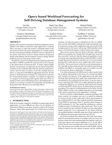
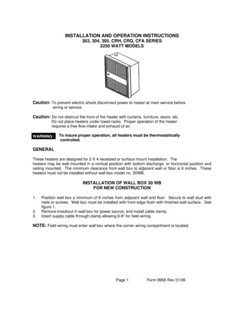
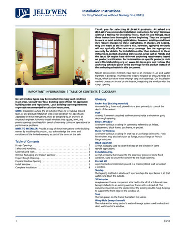
Chapter 7 – Single-Wythe CMU SystemsSINGLE-WYTHE CMU WALL: Window Head DetailLegend161. Typical Assembly:-- Interior gypsum board-- Steel stud-framed wall-- Closed-cell spray foam (CCSPF) insulation between studs (optional)and min. 2 inches continuous CCSPF-- Single-wythe CMU wall with water-repellent admixture atblock and mortar-- Clear water-repellent2. Sealant over backer rod3. Fluid-applied air barrier and WRB flashing membrane4. Continuous air barrier sealant tied to continuous seal at window perimeter5. Storefront window6. Preservative treated wood blocking2345Detail 7-1 Single-Wythe CMU Wall: Window Head DetailDetail DiscussionThe flashing membrane extends from the interior framing to the CMUrough opening. The flashing membrane and the continuous air barriersealant joint provide air and water control layer continuity from thewindow to the CMU wall.Blocking at the window perimeter provides a low-conductivitysolution for mechanically attaching the window as required by thewindow manufacturer.Water-Shedding Surface & Control LayersWater-Shedding SurfaceControl Layers:WaterAirVaporThermalWater-Shedding Surface and Control Layers of Detail 7-1111Colorado Masonry Systems Design Guide
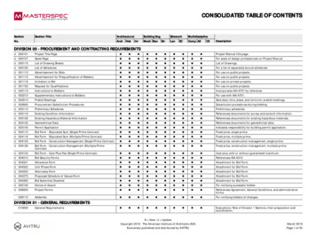
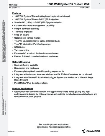
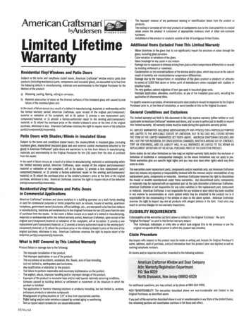
Chapter 7 – Single-Wythe CMU SystemsSINGLE-WYTHE CMU WALL: Window Sill DetailLegend2563741Detail 7-2 Single-Wythe CMU Wall: Window Sill Detail1. Typical Assembly:-- Interior gypsum board-- Steel stud-framed wall-- Closed-cell spray foam (CCSPF) insulation between studs (optional)and min. 2 inches continuous CCSPF-- Single-wythe CMU wall with water-repellent admixture atblock and mortar-- Clear water-repellent2. Storefront window on minimum 1 4-inch thick intermittent shims3. Sealant joint over backer rod (weep at quarter points)4. Sloped precast sill with chamfered drip edge, with sealant over backer rodat precast joints5. Continuous air barrier sealant tied to continuous seal at window perimeter6. Continuous back dam angle at rough opening perimeter, minimum 1-inchtall, with window fastened through the back dam angle per windowmanufacturer recommendations7. Preservative treated wood blockingDetail DiscussionThe slope at the precast sill encourages water to drain away from thewindow rough opening. A chamfer is shown in the underside of theprecast sill to form a drip. This encourages water to shed from the sillbefore reaching the masonry veneer below.Attachment of the window is shown through a structural back dam anglein lieu of down through the sill membrane. This minimizes the risk forwater intrusion into the wall cavity below should water exist within thewindow rough opening. Intermittent shims below the window encouragedrainage of the rough opening. Water that may exist within the roughopening can exit through weeps in the exterior sealant joint.Water-Shedding Surface & Control LayersWater-Shedding SurfaceControl Layers:WaterAirVaporThermalWater-Shedding Surface and Control Layers of Detail 7-2The Rocky Mountain Masonry Institute www.rmmi.org112
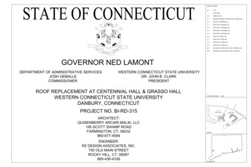
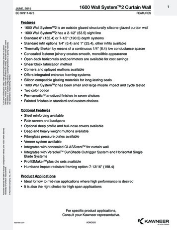
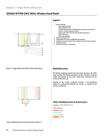
Chapter 7 – Single-Wythe CMU SystemsSINGLE-WYTHE CMU WALL: Window Jamb DetailLegend23511. Typical Assembly:-- Interior gypsum board-- Steel stud-framed wall-- Closed-cell spray foam (CCSPF) insulation between studs (optional)and min. 2 inches continuous CCSPF-- Single-wythe CMU wall with water-repellent admixture atblock and mortar-- Clear water-repellent2. Storefront window3. Sealant joint over backer rod4. Continuous air barrier sealant tied to continuous seal at window perimeter5. Preservative treated wood blocking4Detail 7-3 Single-Wythe CMU Wall: Window Jamb DetailDetail DiscussionThe window is aligned with the rough opening blocking and insulation,rather than with the CMU wall, to provide better continuity of the thermalcontrol layer. The continuous air barrier sealant joint, along with theflashing membrane, provide continuity of the air and water control layer.Water-Shedding Surface & Control LayersWater-Shedding SurfaceControl Layers:WaterAirVaporThermalWater-Shedding Surface and Control Layers of Detail 7-3113Colorado Masonry Systems Design Guide
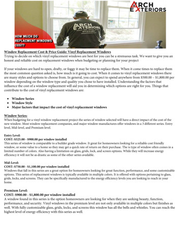
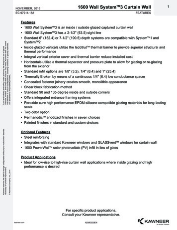
Chapter 7 – Single-Wythe CMU SystemsSINGLE-WYTHE CMU WALL: Base-of-Wall DetailLegend1. Typical Assembly:-- Interior gypsum board-- Steel stud-framed wall-- Closed-cell spray foam (CCSPF) insulation between studs (optional)and min. 2 inches continuous CCSPF-- Single-wythe CMU wall with water-repellent admixture atblock and mortar-- Clear water-repellent2. Rigid XPS insulation3. Underslab vapor barrier4. Rigid XPS underslab insulation5. Hardscape sealant joint6. Damp-proofing (optional)7. Drainage composite or gravel backfill8. Hardscape123456788Detail 7-4 Single-Wythe CMU Wall: Base-of-Wall DetailDetail DiscussionThe XPS insulation provides a thermal break between the concrete floorslab and the single-wythe CMU wall. This allows for thermal continuitybetween the underslab insulation and wall insulation.Water-Shedding Surface & Control LayersWater-Shedding SurfaceControl Layers:WaterAirVaporThermalWater-Shedding Surface and Control Layers of Detail 7-4The Rocky Mountain Masonry Institute www.rmmi.org114
Chapter 7 – Single-Wythe CMU SystemsSINGLE-WYTHE CMU WALL: Roof Parapet DetailLegendSLOPE452631. Typical Assembly:-- Interior gypsum board-- Steel-framed wall-- Closed-cell spray foam (CCSPF) insulation between studs, min. 2 inchescontinuous CCSPF-- Single-wythe CMU wall with water-repellent admixture atblock and mortar-- Clear water-repellent2. Inverted roof membrane assembly3. Typical Parapet Assembly:-- Inverted roof membrane-- Single-wythe CMU wall with water-repellent admixture atblock and mortar-- Clear water repellent4. Standing-seam sheet-metal coping with gasketed washer fasteners5. Preservative-treated wood blocking6. High-temperature self-adhered membrane1Detail 7-5 Single-Wythe CMU Wall: Roof Parapet DetailDetail DiscussionThe sheet-metal coping with hemmed drip edge sheds water awayfrom the wall top and CMU wall face below. It is recommended thatthe sheet-metal coping counterflash the top course of block by aminimum of 3 inches.The CCSPF extends tight up to the underside of the deck and aroundroof structure and anchor elements. This reduces the opportunity forwarm, moisture-laden interior air to contact the deck and CMU wallwhere it’s coldest.Water-Shedding Surface & Control LayersWater-Shedding SurfaceControl Layers:WaterAirVaporThermalWater-Shedding Surface and Control Layers of Detail 7-5115Colorado Masonry Systems Design Guide
Chapter 7 – Single-Wythe CMU SystemsSINGLE-WYTHE CMU WALL: Roof Parapet 3D Detail75896312134210111Detail 7-6 Single-Wythe CMU Wall: Roof Parapet 3D ythe CMU wall with water-repellent admixturePreservative-treated wood blockingRoof structureSteel stud-framed wallSloped, preservative-treated wood blockingInverted roof membrane assemblyHigh-temperature self-adhered membraneSloped standing-seam sheet-metal coping with gasketed washer fastenersRoof membrane terminationContinuous air barrier sealant, tied to continuous seal at window perimeter.Storefront windowClosed-cell spray foam (CCSPF) insulation between studsInterior gypsum boardThe Rocky Mountain Masonry Institute www.rmmi.org116
Chapter 7 – Single-Wythe CMU SystemsSINGLE-WYTHE CMU WALL: Base-of-Wall 3D Detail100911128265743Detail 7-7 Single-Wythe CMU Wall: Base-of-Wall 3D DetailLegend1.2.3.4.5.6.7.8.9.10.11.12.117Concrete floor slab over XPS insulation and vapor barrierSingle-wythe CMU wall with water-repellent admixtureDamp-proofingDrainage composite or gravel backfillHardscape, sloped away from structureHardscape sealant joint between hardscape and CMU wallSteel stud-framed wallClosed-cell spray foam (CCSPF) insulation between studsContinuous air barrier sealant tied to continuous seal at window perimeterFluid-applied flashing membraneStorefront windowSloped precast concrete sillColorado Masonry Systems Design Guide1
2. Storefront window 3. Sealant joint over backer rod 4. Continuous air barrier sealant tied to continuous seal at window perimeter 5. Preservative treated wood blocking SINGLE-WYTHE CMU WALL: Window Jamb Detail Detail 7-3 Single-Wythe CMU Wall: Window Jamb Detail Water-Shedding Surface and Control Layers of Detail 7-3