Transcription
Mike Holt’s Illustrated Guide toNEC Requirements for Generatorsand Standby Power Systems Rule 220.87, Articles 445, 700, 701, and 702Based on the 2011 NEC Extracted from Mike Holt’s Illustrated Guides toUnderstanding the NEC Volumes 1 and 2Visit www.MikeHolt.com for In-House TrainingUse discount code PDFGEN to save 20% on your order.NEC , NFPA 70 , NFPA 70E and National Electrical Code are registered trademarks of the National Fire Protection Association.Mike Holt Enterprises, Inc.1.888.NEC.CODE www.MikeHolt.com Info@MikeHolt.comCOPYRIGHT 2012 Charles Michael Holt1.11.13
I dedicate this book to theLord Jesus Christ,my mentor and teacher.Proverbs 16:3
IntroductionThis small booklet contains a small sample of the 2011 NEC rules related to generators. As a continued service to theindustry, we are making this available at no charge. If you have any suggestions on how it can be improved, pleaselet me know by emailing me at Mike@MikeHolt.com.God bless,Mike HoltMike Holt Enterprises, Inc. www.MikeHolt.com 888.NEC.CODE (632.2633)1
ARTICLE220Branch-Circuit, Feeder,and Service CalculationsIntroduction to Article 220—Branch-Circuit, Feeder, and Service CalculationsThis five-part article focuses on the requirements for calculating the minimum size of branch circuit, feeder, and service conductors.Part I describes the layout of Article 220 and provides a table of where other types of load calculations can be found in the NEC. Part IIprovides requirements for branch-circuit calculations and for specific types of branch circuits. Part III covers the requirements for feederand service calculations, using what’s commonly called the standard method of calculation. Part IV provides optional calculations thatcan be used in place of the standard calculations provided in Parts II and III—if your installation meets certain requirements. Farm LoadCalculations are discussed in Part V of the article.In many cases, either the standard method (Part III) or the optional method (Part IV) can be used; however, these two methods don’t yieldidentical results. In fact, sometimes these two answers may be diverse enough to call for different service sizes. There’s nothing to say thateither answer is right or wrong. If taking an exam, read the instructions carefully to be sure which method the test wants you to use. As youwork through Article 220, be sure to study the illustrations to help you fully understand it. Also be sure to review the examples in Annex D ofthe NEC to provide more practice with these calculations.220.87 Determining Existing Loads. The calculation of afeeder or service load for existing installations can be based on:(1) The maximum demand data for one year.Ex: If the maximum demand data for one year isn’t available, the maximum power demand over a 15-minute period continuously recordedover a minimum 30-day period using a recording ammeter or powermeter connected to the highest loaded phase, based on the initialloading at the start of the recording is permitted. The recording mustbe taken when the building or space is occupied based on the largerof the heating or cooling equipment load.Mike Holt Enterprises, Inc. www.MikeHolt.com 888.NEC.CODE (632.2633)2
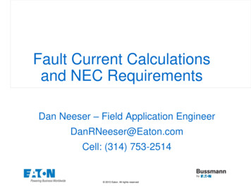
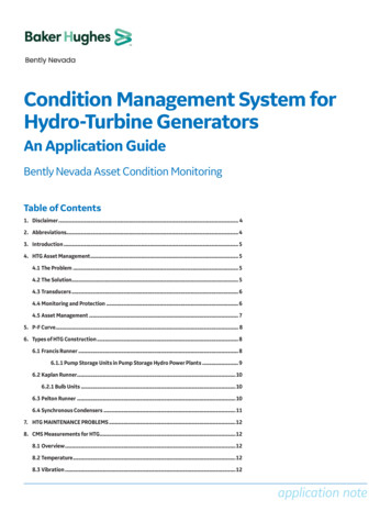
ARTICLE445GeneratorsIntroduction to Article 445—GeneratorsThis article contains the electrical installation, and other requirements, for generators. These requirements include such things as wheregenerators can be installed, nameplate markings, conductor ampacity, and disconnecting means.Generators are basically motors that operate in reverse—they produce electricity when rotated, instead of rotating when supplied with electricity. Article 430, which covers motors, is the longest article in the NEC. Article 445, which covers generators, is one of the shortest. At first,this might not seem to make sense. But you don’t need to size and protect conductors to a generator. You do need to size and protect themto a motor.Generators need overload protection, and it’s necessary to size the conductors that come from the generator. But these considerations aremuch more straightforward than the equivalent considerations for motors. Before you study Article 445, take a moment to read the definitionof “Separately Derived System” in Article 100.445.1 Scope. Article 445 contains the installation and other445.13 Ampacity of Conductors. The ampacity of the con-requirements for generators.ductors from the generator to distribution devices containing overcurrent protection must not be less than 115 percent of the nameplatecurrent rating of the generator. Figure 445–1Author’s Comment: Generators, associated wiring, andequipment must be installed in accordance with the followingrequirements depending on their use: Article 695, Fire Pumps Article 700, Emergency Systems Article 701, Legally Required Standby Systems Article 702, Optional Standby Systems445.11 Marking. Each generator must be provided with a nameplate indicating the manufacturer’s name, rated frequency, powerfactor, number of phases, rating in kilowatts or kilovolt amperes, voltsand amperes corresponding to the rating, RPM, insulation class andrated ambient temperature or rated temperature rise, and time rating.445.12 Overcurrent Protection.(A) Generators. Generators must be protected from overload byinherent design, circuit breakers, fuses, or other identified overcurrentprotective means.Figure 445–1Generators that aren’t a separately derived system must have theneutral conductor sized to: Figure 445–2Mike Holt Enterprises, Inc. www.MikeHolt.com 888.NEC.CODE (632.2633)3
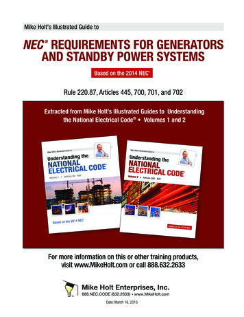
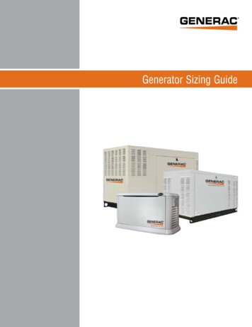
NEC Requirements for Generators and Standby Power SystemsFigure 445–4Figure 445–2 Carry the maximum unbalanced current as determined by220.61.Serve as the low-impedance fault current path.Author’s Comment: If the feeder conductors from the generator terminate in a transfer switch that doesn’t open the neutralconductor, the generator isn’t considered a separately derivedsystem [250.30 Note 1]. Figure 445–3. A neutral-to-case bondisn’t permitted at the generator. Under this condition, the neutralconductor from the normal power to the transfer switch, and theneutral conductor from the generator to the transfer switch, arerequired to provide the low-impedance fault current path back tothe power source. Figure 445–4Separately derived system generators must have the neutral conductor sized not less than required to carry the maximum unbalancedcurrent as determined by 220.61.Author’s Comment: If the feeder conductors from the generator terminate in a transfer switch that opens the neutralconductor, the generator is considered a separately derivedsystem [Article100]. Figure 445–5. A neutral-to-case connection (system bonding jumper) is required at the generator[250.30(A)(1)] to provide a low-impedance fault current pathback to the power source. Figure 445–6Figure 445–5Figure 445–3Mike Holt Enterprises, Inc. www.MikeHolt.com 888.NEC.CODE (632.2633)4
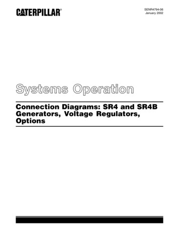
NEC Requirements for Generators and Standby Power SystemsFigure 445–7Figure 445–6445.18 Disconnecting Means. Generators must have one or(1) The driving means for the generator can be readily shut down,andCaution: If one generator is used to supply emergency, legally required, as well as optional standbypower, then there must be at least two transferswitches; one for emergency power and another for legallyrequired as well as optional stand-by power [700.6(D)].(2) The generator isn’t arranged to operate in parallel with anothergenerator or other source of voltage.445.19 Generators Supplying Multiple Loads. A singlemore disconnecting means that disconnects all power, except where:Figure 445–7generator is permitted to supply more than one load.Mike Holt Enterprises, Inc. www.MikeHolt.com 888.NEC.CODE (632.2633)5
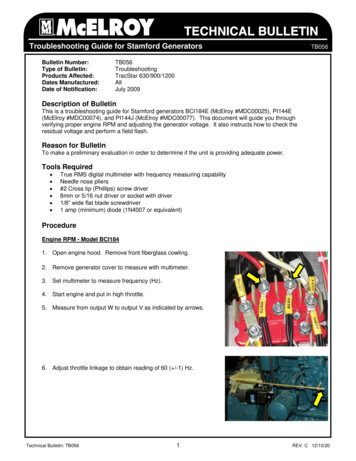
ARTICLE700Emergency SystemsIntroduction to Article 700—Emergency SystemsEmergency systems are legally required, often as a condition of an operating permit for a given facility. The authority having jurisdictionmakes the determination as to whether such a system is necessary for a given facility and what it must entail. Sometimes, it simplyprovides power for exit lighting and exit signs upon loss of main power or in the case of fire. Its purpose isn’t to provide power for normalbusiness operations, but rather to provide lighting and controls essential for human life safety.The general goal is to keep the emergency operation as reliable as possible. The emergency system must be able to supply all emergencyloads simultaneously. When the emergency supply also supplies power for other nonemergency loads, the emergency loads take priorityover the other loads, and those other loads must be subject to automatic load pickup and load shedding to support the emergency loads ifthe emergency system doesn’t have adequate capacity and rating for all loads simultaneously.As you study Article 700, keep in mind that emergency systems are essentially lifelines for people. The entire article is based on keepingthose lifelines from breaking.Part I. General700.1 Scope. Article 700 applies to the installation, operation,and maintenance of emergency systems. These consist of circuits andequipment intended to supply illumination or power within 10 seconds [700.12] when the normal electrical supply is interrupted. Figure700–1Note 3: Emergency systems are generally installed where artificial illumination is required for safe exiting and for panic control inbuildings subject to occupancy by large numbers of persons, suchas hotels, theaters, sports arenas, health care facilities, and similar institutions.Emergency systems may also provide power to maintain life, firedetection and alarm systems, elevators, fire pumps, public safetycommunications systems, industrial processes where current interruption would produce serious life safety or health hazards, and similar functions.Note 4: For specific locations where emergency lighting is required,see NFPA 101, Life Safety Code.Figure 700–1700.2 Definitions.Emergency Systems. Emergency systems are those systems legallyrequired and classed as emergency by a governmental agency havingjurisdiction. These systems are intended to automatically supply illumination and/or power essential for safety to human life. Figure700–2Mike Holt Enterprises, Inc. www.MikeHolt.com 888.NEC.CODE (632.2633)6
NEC Requirements for Generators and Standby Power Systems700.4 Capacity.(A) Capacity and Rating. An emergency system must have adequate capacity to carry all emergency loads expected to operatesimultaneously.(B) Load Shedding. If an alternate power supply has adequatecapacity, it’s permitted to supply emergency loads [Article 700],legally required standby loads [Article 701], and optional standbysystem loads [Article 702]. If the alternate power supply doesn’t haveadequate capacity to carry the entire load, it must have automaticselective load pickup and load shedding to ensure adequate power inthe following order of priority:(1) The emergency circuits,(2) The legally required standby circuits, andFigure 700–2(3) The optional standby circuits.Relay, Automatic Load Control. A device used to energize switchedor normally off lighting equipment from an emergency supply in theevent of loss of the normal supply and to de-energize or return theequipment to normal status when the normal supply is restored.700.3 Tests and Maintenance. Emergency system testingconsists of acceptance testing and operational testing.(A) Conduct or Witness Test. To ensure that the emergency systemmeets or exceeds the original installation specifications, the authorityhaving jurisdiction must conduct or witness an acceptance test of theemergency power system upon completion.A temporary alternate source of power must be available wheneverthe emergency generator is out of service for more than a few hoursfor maintenance or repair.700.5 Transfer Equipment.(A) General. Transfer equipment must be automatic, identified foremergency use, and approved by the authority having jurisdiction.(C) Automatic Transfer Switches. Automatic transfer switches mustbe electrically operated, mechanically held, and listed for emergencypower system use. Figure 700–3(B) Periodic Testing. Emergency systems must be periodically testedto ensure that adequate maintenance has been performed and thatthe systems are in proper operating condition.Author’s Comment: Running the emergency system underload is often considered an acceptable method of operationaltesting.(C) Battery Systems Maintenance. If batteries are used, the authority having jurisdiction is to require periodic maintenance.(D) Written Record. A written record must be kept of all requiredtests [700.4(A) and (B)] and maintenance [700.4(C)].Author’s Comment: The NEC doesn’t specify the requiredrecord retention period.Figure 700–3Mike Holt Enterprises, Inc. www.MikeHolt.com 888.NEC.CODE (632.2633)7
NEC Requirements for Generators and Standby Power Systems(D) Use. Transfer equipment must supply only emergency loads.Figure 700–4Part II. Circuit Wiring700.10 Wiring.(A) Identification. Boxes and enclosures, including transfer switches,generators, and power panels for emergency circuits must be permanently marked as components of an emergency power system. Figure700–6Figure 700–4Author’s Comment: Multiple transfer switches are requiredwhere a single generator is used to supply both emergencyloads and other loads.700.7 Signs.(A) Emergency Sources. A sign must be placed at the serviceentrance equipment indicating the type and location of on-site emergency power sources. Figure 700–5Figure 700–6(B) Wiring. To ensure that a fault on the normal wiring circuits won’taffect the performance of emergency wiring or equipment, all wiringto emergency loads must be kept entirely independent of all otherwiring, except:(1) Wiring in transfer equipment. Figure 700–7(2) Luminaires supplied from two sources of power.(3) A junction box attached to luminaires supplied from two sourcesof power.
This five-part article focuses on the requirements for calculating the minimum size of branch circuit, feeder, and service conductors. Part I describes the layout of Article 220 and provides a table of where other types of load calculations can be found in the NEC. Part II