Transcription
Automotive High-VoltageSwitcher for Low PowerOffline SMPSNCV1060, NCV1063The NCV106X products integrate a fixed frequency current modecontroller with a 670 V MOSFET. Available in a SOIC 10 orSOIC 16 package, the NCV106X offer a high level of integration,including soft start, frequency jittering, short circuit protection,skip cycle, adjustable peak current set point, ramp compensation, and aDynamic Self Supply (eliminating the need for an auxiliary winding).Unlike other monolithic solutions, the NCV106X is quiet by nature:during nominal load operation, the part switches at one of the availablefrequencies (60 kHz or 100 kHz). When the output power demanddiminishes, the IC automatically enters frequency foldback mode andprovides excellent efficiency at light loads. When the power demandreduces further, it enters into a skip mode to reduce the standbyconsumption down to a no load condition.Protection features include: a timer to detect an overload or ashort circuit event, Overvoltage Protection with auto recovery andAC input line voltage detection (A version).The ON proprietary integrated Over Power Protection (OPP) letsyou harness the maximum delivered power without affecting yourstandby performance simply via external resistors.For improved standby performance, the connection of an auxiliarywinding stops the DSS operation and helps to reduce input powerconsumption below 50 mW at high line.NCV106x can be seamlessly used both in non isolated and inisolated topologies.www.onsemi.comMARKING DIAGRAMS161101 Semiconductor Components Industries, LLC, 2018March, 2021 Rev. 21SOIC 10CASE 751BQAD or BD SUFFIX1V1060fyyyALYWXGx Power Switch CircuitOn state Resistance(0 34 W, 3 11.4 W)f Brown In (A Yes, B No)yyy Oscillator Frequency(060 60 kHz, 100 100 kHz)A Assembly LocationL, WL Wafer LotY, YY YearW, WW Work WeekG or G Pb Free Package Built in 670 V MOSFET with RDS(on) of 34 W (NCV1060) and11.4 W (NCV1063)Large Creepage Distance Between High voltage PinsCurrent Mode Fixed Frequency Operation – 60 kHz or 100 kHzAdjustable Peak Current: see below tableFixed Ramp CompensationDirect Feedback Connection for Non isolated ConverterInternal and Adjustable Over Power Protection (OPP) CircuitSkip Cycle Operation at Low Peak Currents OnlyDynamic Self Supply: No Need for an Auxiliary WindingInternal 4 ms Soft StartAuto Recovery Output Short Circuit Protection with Timer BasedDetectionAuto Recovery Overvoltage Protection with Auxiliary WindingOperationFrequency Jittering for Better EMI SignatureNo Load Input Consumption 50 mWNCV1063fyyyGAWLYWW10Features 16SOIC 16CASE 751B 05D SUFFIX1ORDERING INFORMATIONSee detailed ordering and shipping information on page 28 ofthis data sheet. Frequency Foldback to Improve Efficiency at Light LoadNCV Prefix for Automotive and OtherApplications Requiring Unique Site andControl Change Requirements; AEC Q100Qualified and PPAP CapableThese Devices are Pb Free and are RoHSCompliantTypical Applications Auxiliary & Standby Isolated Power Supplies for HEV/EVPublication Order Number:NCV1060/D
NCV1060, NCV1063Table 1. PRODUCT INFORMATION & INDICATIVE MAXIMUM OUTPUT POWER230 Vac 15%85 265 VacProductRDS(on)IIPK(0)AdapterOpen FrameAdapterOpen FrameNCV1060 60 kHz34 W300 mA2.9 W7.2 W1.7 W4.1 WNCV1063 100 kHz11.4 W780 mA6.9 W17.1 W3.7 W8.6 WNOTE:Informative values only, with Tamb 25 C, Tcase 100 C, SOIC 10 package for NCV1060 and SOIC 16 package for NCV1063,Self supply via Auxiliary winding and circuit mounted on minimum copper area as DRAINDRAINDRAINDRAINSOIC 10SOIC 16Figure 1. Pin ConnectionsTable 2. PIN FUNCTION DESCRIPTIONPin NoSOIC 10SOIC 16Pin NameFunction11 4GNDThe IC Ground25VCCPowers the InternalCircuitryThis pin is connected to an external capacitor. The VDD includes anauto recovery over voltage protection36LIM/OPPIpeak Set / OverPower LimitationThe current drown from the pin decreases Ipeak of the primarywinding. If resistive divider from the auxiliary winding is connected tothis pin it sets the OPP compensation level (it diminishes the peakcurrent.)47FBFeedback SignalInputThis is the inverting input of the trans conductance error amplifier. Itis normally connected to the switching power supply output througha resistor divider58CompCompensationThe error amplifier output is available on this pin. The networkconnected between this pin and ground adjusts the regulation loopbandwidth. Also, by connecting an opto coupler to this pin, the peakcurrent set point is adjusted accordingly to the output power demand9 126 1013 16Pin DescriptionThis un connected pin ensures adequate creepage distanceDrainDrain ConnectionThe internal drain MOSFET connectionwww.onsemi.com2
NCV1060, NCV1063Table 3. TYPICAL APPLICATIONS If the output voltage is above9.0 V typ. (between VCC(on)level and VOVP level) VCC issupplied from output via D2 If the output voltage is below9.0 V, D2 is redundant, the ICis supplied from DSS R2 limits maximum outputpower (can be omitted if notrequired) Direct feedback, resistivedivider formed by R3, R4 setsoutput voltage If the output voltage is above9.0 V typ. (between VCC(on)level and VOVP level) VCC issupplied from output via D3 If the output voltage is below9.0 V, D3 and C5 areredundant, the IC is suppliedfrom DSS R2 limits maximum outputpower (can be omitted if notrequired) Optocoupler feedbackTypical Non isolated Application – Buck Converter If the output voltage is above9.0 V typ. between VCC(ON)level and VOVP level VCCsupplied from output via D2 R2 limits maximal outputpower Direct feedback, resistivedivider formed by R3, R4 setsoutput voltage VCC supplied from DSS Output voltage is below 9.0 Vtyp. LIM/OPP pin floating no limitoutput power Direct feedback, resistivedivider formed by R2, R3 setsoutput voltageTypical Non isolated Application – Buck Boost Converterwww.onsemi.com3
NCV1060, NCV1063Table 3. TYPICAL APPLICATIONS (continued) VCC supplied from DSS Output voltage is below 9.0 Vtyp. LIM/OPP pin floating no limitoutput power Resistive divider formed by R2,R3 sets output voltage If the output voltage is above9.0 V typ. between VCC(ON)level and VOVP level VCCsupplied from output via D4 LIM/OPP pin floating no limitoutput power Resistive divider formed by R2,R3 sets output voltageTypical Non isolated Application – Flyback Converter VCC supplied from auxiliarywinding Resistive divider formed by R2,R3 sets output power limit andover power protection Optocoupler feedback, resistive divider formed by R6, R7sets output voltageTypical Isolated Application – Flyback Converterwww.onsemi.com4
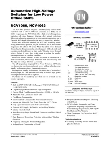
NCV1060, NCV1063DRAINVCC80 ms FilterSCPVOVPI pflagSOFF UVLOQt SCPRtrecoveryVCOMP(REF esetVddVCCManagementVCC OVPTSDVCCSawtoothR sationSKIP ”1” è Shut down someblocks to reduce aultICOMP to CS setpointResetI FreezeI LMDECIFBSoft StartIpk(0)Reset SS as recoving fromSCP, TSD, VCC OVP or UVLOFB0ILMOP (min)ILMDECILMOP (max )ILMOPI LMOPIPKLVLMOPLIM/OPPFigure 2. Simplified Internal Circuit Architecturewww.onsemi.com5
NCV1060, NCV1063Table 4. MAXIMUM RATING TABLE (All voltages related to GND terminal)SymbolValueUnitVCC 0.3 to 20VVoltage on all pins, except Drain and VCC pinVinmax 0.3 to 10VDrain voltageBVdss 0.3 to 670VICC10mARatingPower supply voltage, VCC pin, continuous voltageMaximum Current into VCC pinDrain Current Peak during Transformer Saturation (TJ 150 C, Note 2):NCV1060NCV1063Drain Current Peak during Transformer Saturation (TJ 125 C, Note 2):NCV1060NCV1063Drain Current Peak during Transformer Saturation (TJ 25 C, Note al Resistance, Junction to Air – SOIC10 with 200 mm@ of 35 m copper areaRθJA132 C/WThermal Resistance, Junction to Air – SOIC16 with 200 mm@ of 35 m copper areaRθJA104 C/WJunction to Top Thermal Characterization Parameter – SOIC10YJT2.3 C/WJunction to Top Thermal Characterization Parameter – SOIC16YJT2.5 C/WJunction Temperature RangeTJ 40 to 150 CStorage Temperature RangeTstg 60 to 150 CHuman Body Model ESD Capability (All pins except HV pin) per AEC Q100 002(JESD22 A114F)HBM2kVCharged Device Model ESD Capability per AEC Q100 11(JESD22 C101E)CDM1kVStresses exceeding those listed in the Maximum Ratings table may damage the device. If any of these limits are exceeded, device functionalityshould not be assumed, damage may occur and reliability may be affected.1. This device contains latch up protection and exceeds 100 mA per JEDEC Standard JESD78.2. Maximum drain current IDS(PK) is obtained when the transformer saturates. It should not be mixed with short pulses that can be seen at turnon. Figure 3 below provides spike limits the device can tolerate.Figure 3. Spike Limitswww.onsemi.com6
NCV1060, NCV1063Table 5. ELECTRICAL CHARACTERISTICS(For typical values TJ 25 C, for min/max values TJ 40 C to 125 C, VCC 14 V unless otherwise noted)SymbolRatingPinMinTypMaxUnitSUPPLY SECTION AND VCC MANAGEMENTVCC(on)VCC increasing level at which the switcher starts operation2 (5)8.49.09.5VVCC(min)VCC decreasing level at which the HV current source restarts2 (5)7.07.57.8VVCC(off)VCC decreasing level at which the switcher stops operation (UVLO)2 (5)6.77.07.2VInternal IC consumption, NCV1060 switching at 60 kHz, LIM/OPP 0 AInternal IC consumption, NCV1060 switching at 100 kHz, LIM/OPP 0 AInternal IC consumption, NCV1063 switching at 60 kHz, LIM/OPP 0 AInternal IC consumption, NCV1063 switching at 100 kHz, LIM/OPP 0 A2 (5) 0.920.970.991.07 mAInternal IC consumption, COMP is 0 V (No switching on MOSFET)2 (5) 340 mAICC1ICCskipPOWER SWITCH CIRCUITPower Switch Circuit on state resistanceNCV1060 (Id 50 mA)Tj 25 CTj 125 CNCV1063 (Id 50 mA)Tj 25 CTj 125 C7, 8(6 10)(13 16)BVDSSPower Switch Circuit & Startup breakdown voltage(ID(off) 120 mA, Tj 25 C)IDSS(off)RDS(on)trtfton(min)W 34654172 11.42214.0247, 8(6 10)(13 16)670 VPower Switch & Startup breakdown voltage off state leakage currentTj 125 C (Vds 670 V)7, 8(6 10)(13 16) 84 mASwitching characteristics (RL 50 W, VDS set for Idrain 0.7 x Ilim)Turn on time (90% 10%)Turn off time (10% 90%)7, 8(6 10)(13 16) 2010 Minimum on timeNCV1060NCV10637, 8(6 10)(13 16) 200230 nsnsINTERNAL START UP CURRENT SOURCEIstart1High voltage current source, VCC VCC(on) – 200 mV7, 8(6 10)(13 16)5812mAIstart2High voltage current source, VCC 0 V7, 8(6 10)(13 16) 0.5 mA2 (5) 1.4 V21VVCCTHVstart(min)VCC Transient level for Istart1 to Istart2 toggling pointMinimum startup voltage, VCC 0 V7, 8(6 10)(13 16)CURRENT COMPARATORIIPKIIPK(0)Maximum internal current setpoint at 50% duty cycleFB 2 V, LIM/OPP 0 mA, Tj 25 CNCV1060NCV1063mA Maximum internal current setpoint at beginning of switching cycleFB 2 V, LIM/OPP pin open Tj 25 CNCV1060NCV1063 250650 mA 2687023007803328583. The final switch current is: IIPK(0) / (Vin/LP Sa) x Vin/LP Vin/LP x tprop, with Sa the built in slope compensation, Vin the input voltage,LP the primary inductor in a flyback, and tprop the propagation delay.4. Oscillator frequency is measured with disabled jittering.www.onsemi.com7
NCV1060, NCV1063Table 5. ELECTRICAL CHARACTERISTICS (continued)(For typical values TJ 25 C, for min/max values TJ 40 C to 125 C, VCC 14 V unless otherwise noted)SymbolRatingPinMinTypMaxUnitCURRENT COMPARATORIIPKSWIIPKSWILMDECFinal switch current with a primary slope of 200 mA/ms,FSW 60 kHz (Note 3), LIM/OPP pin openNCV1060NCV1063Final switch current with a primary slope of 200 mA/ms,FSW 100 kHz (Note 3), LIM/OPP pin openNCV1060NCV1063mA 330740 mA 320710 Maximum internal current setpoint at beginning of switching cycleFB 2 V, LIM/OPP 285 mA, Tj 25 CNCV1060NCV1063mA 128312 tSSSoft start duration (guaranteed by design) 4 mstpropPropagation delay from current detection to drain OFF state 70 nstLEBLeading Edge Blanking DurationNCV1060NCV1063 130160 nsINTERNAL OSCILLATORfOSCOscillation frequency, 60 kHz version, Tj 25 C (Note 4) 546066kHzfOSCOscillation frequency, 100 kHz version, Tj 25 C (Note 4) 90100110kHzfjitterFrequency jittering in percentage of fOSC 6 %fswingJittering swing frequency 300 HzDmaxMaximum duty cycle 626672%Voltage Feedback Input (VCOMP 2.5 V)4 (7)3.23.33.4VIFBInput Bias Current (VFB 3.3 V)4 (7) 1 mAGMERROR AMPLIFIER SECTIONVREFTransconductance5 (8)2mSIOTAlimOTA maximum current capability (VFB VOTAen)5 (8) 150mAVOTAenFB voltage to disable OTA4 (7)0.71.31.7VCOMPENSATION SECTIONICOMPfaultCOMP current for which Fault is detected5 (8) 40 mAICOMP100%COMP current for which internal current set point is 100% (IIPK(0))5 (8) 44 mAICOMPfreezeCOMP current for which internal current setpoint is:IFreeze1 or 2 (NCV1060/3)5 (8) 80 mAVCOMP(REF)Equivalent pull up voltage in linear regulation range(Guaranteed by design)5 (8) 2.7 VEquivalent feedback resistor in linear regulation range(Guaranteed by design)5 (8) 17.7 kΩVLMOPVoltage on LIM/OPP pin @ ILMOP 35 mAVoltage on LIM/OPP pin @ ILMOP 250 mA, Tj 25 C3 (6)1.401.281.501.351.601.42VILMOP 330 420mA 26 32mARCOMP(up)Maximum current from LIM/OPP pin3 (6)ILMOP(min)Current at which LIM/OPP starts to decrease IPEAK3 (6)ILMOP(max)Current at which LIM/OPP stops to decrease IPEAK3 (6) 285mAILMOP(neg)Negative Active Clamp Voltage (ILMOP 2.5 mA)3 (6) 0.7V 203. The final switch current is: IIPK(0) / (Vin/LP Sa) x Vin/LP Vin/LP x tprop, with Sa the built in slope compensation, Vin the input voltage,LP the primary inductor in a flyback, and tprop the propagation delay.4. Oscillator frequency is measured with disabled jittering.www.onsemi.com8
NCV1060, NCV1063Table 5. ELECTRICAL CHARACTERISTICS (continued)(For typical values TJ 25 C, for min/max values TJ 40 C to 125 C, VCC 14 V unless otherwise noted)SymbolRatingPinMinTypMaxUnitCOMPENSATION SECTIONILMOP(pos)Positive Active Clamp (Guaranteed by design)3 (6)2.5mAFREQUENCY FOLDBACK & SKIPICOMPfoldStart of frequency foldback COMP pin current levelICOMPfold(end) End of frequency foldback COMP pin current level, fsw fmin5 (8) 68 mA5 (8) 100 mAkHzfminThe frequency below which skip cycle occurs 212529ICOMPskipThe COMP pin current level to enter skip mode5 (8) 120 mAIFreeze1Internal minimum current setpoint (ICOMP ICOMPFreeze) in NCV1060 110 mAIFreeze2Internal minimum current setpoint (ICOMP ICOMPFreeze) in NCV1063 270 mARAMP COMPENSATIONSa(60)The internal ramp compensation @ 60 kHz:NCV1060NCV1063 8.415.6 Sa(100)The internal ramp compensation @ 100 kHz:NCV1060NCV1063 1426 Fault validation further to error flag assertion 3548 msOFF phase in fault mode 400 ms2 (5)17.018.018.8V 80 ms7,8(6 10)(13 CC voltage at which the switcher stops pulsingtOVPThe filter of VCC OVP comparatorVHV(EN)The drain pin voltage above which allows MOSFET operate, which isdetected after TSD, UVLO, SCP, or VCC OVP mode. (A version only)TEMPERATURE MANAGEMENTTSDTemperature shutdown (Guaranteed by design) 150163 CTSDhystHysteresis in shutdown (Guaranteed by design) 20 C3. The final switch current is: IIPK(0) / (Vin/LP Sa) x Vin/LP Vin/LP x tprop, with Sa the built in slope compensation, Vin the input voltage,LP the primary inductor in a flyback, and tprop the propagation delay.4. Oscillator frequency is measured with disabled jittering.Product parametric performance is indicated in the Electrical Characteristics for the listed test conditions, unless otherwise noted. Productperformance may not be indicated by the Electrical Characteristics if operated under different conditions.www.onsemi.com9
NCV1060, NCV1063TYPICAL CHARACTERISTICS9.157.527.507.489.05VOLTAGE (V)VOLTAGE 5 40 200204060801007.32 40120 20020406080100TEMPERATURE ( C)TEMPERATURE ( C)Figure 4. VCC(on) vs. TemperatureFigure 5. VCC(min) vs. Temperature1208007.007006.98CURRENT (mA)VOLTAGE (V)6006.966.946.925004003002006.90 200204060801000 40120020406080100TEMPERATURE ( C)Figure 6. VCC(off) vs. TemperatureFigure 7. IDSS(off) vs. 0.960.950.940.930.890.88 40 20TEMPERATURE ( C)CURRENT (mA)CURRENT (mA)6.88 40100 200204060801000.92 40120 20020406080100TEMPERATURE ( C)TEMPERATURE ( C)Figure 8. ICC1 60 kHz vs. TemperatureFigure 9. ICC1 100 kHz vs. Temperaturewww.onsemi.com10120
NCV1060, NCV1063310770308765306760CURRENT (mA)304302300298296294750745740735292290288 40 20725720 40020406080100120020406080100TEMPERATURE ( C)Figure 10. IIPK(0)1060 vs. TemperatureFigure 11. IIPK(0)1063 vs. Temperature120.6100.58641200.40.30.20.10 40 200204060801000 40120 20020406080100TEMPERATURE ( C)TEMPERATURE ( C)Figure 12. Istart1 vs. TemperatureFigure 13. Istart2 vs. Temperature70120256020RESISTIVITY (W)5040302015105100 40 20TEMPERATURE ( C)2RESISTIVITY (W)755730CURRENT (mA)CURRENT (mA)CURRENT (mA)TYPICAL CHARACTERISTICS 200204060801000 40120 20020406080100TEMPERATURE ( C)TEMPERATURE ( C)Figure 14. RDS(on)1060 vs. TemperatureFigure 15. RDS(on)1063 vs. Temperaturewww.onsemi.com11120
NCV1060, NCV106360.010059.59959.098FREQUENCY (kHz)FREQUENCY (kHz)TYPICAL CHARACTERISTICS58.558.057.557.056.5 200204060801009492 4012020406080100Figure 16. fOSC60 vs. TemperatureFigure 17. fOSC100 vs. 258020406080100256 40120120268102 20020406080100TEMPERATURE ( C)TEMPERATURE ( C)Figure 18. Ifreeze1060 vs. TemperatureFigure 19. Ifreeze1063 vs. Temperature12025.866.225.6FREQUENCY (kHz)66.166.065.965.865.765.6 400TEMPERATURE ( C)274 20 20TEMPERATURE ( C)CURRENT (mA)CURRENT (mA)95109100 40DUTY CYCLE (%)969356.055.5 409725.425.225.024.824.6 2002040608010024.4 40 20120020406080TEMPERATURE ( C)TEMPERATURE ( C)Figure 20. D(max) vs. TemperatureFigure 21. fmin vs. Temperaturewww.onsemi.com12100120
NCV1060, NCV1063TYPICAL CHARACTERISTICS534304255242051TIME (ms)TIME (ms)4154104054004739002040608010046 40120020406080100TEMPERATURE ( C)Figure 22. trecovery vs. TemperatureFigure 23. tSCP vs. Temperature9218.19118.09017.917.817.788878617.585 2002040608010084 40120 20020406080100TEMPERATURE ( C)TEMPERATURE ( C)Figure 24. VOVP vs. TemperatureFigure 25. VHV(EN) vs. E (V)3.313.303.293.283.271.00.80.60.43.263.253.24 40 20TEMPERATURE ( C)VOLTAGE (V)VOLTAGE (V) 2018.217.4 40VOLTAGE (V)4948395385 40500.2 200204060801000 40120 20020406080100TEMPERATURE ( C)TEMPERATURE ( C)Figure 26. VREF vs. TemperatureFigure 27. VOTAen vs. Temperaturewww.onsemi.com13120
NCV1060, NCV1063TYPICAL CHARACTERISTICS1.1002.5NCV10631.075BVDSS/BVDSS (25 C)( )IDS(PK) (A)2.01.51.0NCV10600.51.0501.0251.0000.9750.9500 50 2502550751001250.925 40150 20020406080100125TJ, JUNCTION TEMPERATURE ( C)TEMPERATURE ( C)Figure 28. Drain Current Peak during TransformerSaturation vs. Junction TemperatureFigure 29. Breakdown Voltage vs. Temperaturewww.onsemi.com14
NCV1060, NCV1063APPLICATION INFORMATION If the drain voltage is lower than the internal thresholdIntroductionThe NCV106X offers a complete current mode controlsolution. The component integrates everything needed tobuild a rugged and cost effective Switch Mode PowerSupply (SMPS) featuring low standby power. The QuickSelection Table, Table 6, details the differences betweenreferences, mainly peak current setpoints, RDS(on) value andoperating frequency. Current mode Operation: the controller usescurrent mode control architecture. 670 V – Power MOSFET: Due to ON SemiconductorVery High Voltage Integrated Circuit technology, thecircuit hosts a high voltage power MOSFET featuringa 34 W or 11.4 W RDS(on) – Tj 25 C. This value letsthe designer build a power supply up to 8.6 W or17.1 W operated on universal mains. An internalcurrent source delivers the startup current, necessary tocrank the power supply. Dynamic Self supply: Due to the internal high voltagecurrent source, this device could be used in theapplication without the auxiliary winding to providesupply voltage. Short Circuit Protection: by permanently monitoringthe COMP line activity, the IC is able to detect thepresence of a short circuit, immediately reducing theoutput power for a total system protection. A tSCP timeris started as soon as the COMP current is belowthreshold, ICOMPfault, which indicates the maximumpeak current. If at the end of this timer the fault is stillpresent, then the device enters a safe, auto recoveryburst mode, affected by a fixed timer recurrence,trecovery. Once the short has disappeared, the controllerresumes and goes back to normal operation. Built in VCC Over Voltage Protection: when theauxiliary winding is used to bias the VCC pin (no DSS),an internal comparator is connected to VCC pin. In casethe voltage on the pin exceeds a level of VOVP (18 Vtypically), the controller immediately stops switchingand waits a full timer period (trecovery) beforeattempting to restart. If the fault is gone, the controllerresumes operation. If the fault is still there, e.g. abroken opto coupler, the controller protects the loadthrough a safe burst mode. Line Detection: An internal comparator monitors thedrain voltage as recovering from one of the followingsituations: Short Circuit Protection, VCC OVP is confirmed, UVLO, TSD (VHV(EN)), the internal power switch is inhibited. Thisavoids operating at too low ac input. This is also calledbrown in function in some fields. For applications notusing standard AC mains (24 Vdc industrial bus forinstance), the B version doesn’t incorporate this linedetection and let the device start as soon as voltagesupply reaches Vstart(min).Frequency Jittering: an internal low frequencymodulation signal varies the pace at which theoscillator frequency is modulated. This helps spreadingout energy in conducted noise analysis. To improve theEMI signature at low power levels, the jittering remainsactive in frequency foldback mode.Soft start: a 4 ms soft start ensures a smooth startupsequence, reducing output overshoots.Frequency Foldback Capability: a continuous flow ofpulses is not compatible with no load/light loadstandby power requirements. To excel in this domain,the controller observes the COMP pin currentinformation and when it reaches a level of ICOMPfold,the oscillator then starts to reduce its switchingfrequency as the feedback current continues to increase(the power demand continues to reduce). It can godown to 25 kHz (typical) reached for a feedback levelof ICOMPfold(end) (100 mA roughly). At this point, if thepower continues to drop, the controller enters classicalskip cycle mode.Skip: if SMPS naturally exhibits a good efficiency atnominal load, it begins to be less efficient when theoutput power demand diminishes. By skippingun needed switching cycles, the NCV106X drasticallyreduces the power wasted during light load conditions.Ipeak Set: If current in range 26 mA and 285 mA isdrawn from the pin, the peak current is proportionallyreduced down to 40% of its original value. This featureenables to designer to set up the peak current to thevalue which is ideal for the application.By routing a portion of the negative voltage present duringthe on time on the auxiliary winding to the LIM/OPP pin,the user has a simple and non dissipative means to alter themaximum peak current setpoint as the bulk voltageincreases.www.onsemi.com15
NCV1060, NCV1063Startup Sequenceabove VHV(EN) level (87 V typically) for A version and ifbulk voltage is above Vstart(min) (21 V dc) for B version.There is no disable level for drain pin voltage, the device willstop switching when the input voltage is removed andsub sequentially the VCC reaches the VCC(OFF) level, ortSCP timer elapses. Figure 30 details the simplified internalcircuitry.When the power supply is first powered from the mainsoutlet, the internal current source (typically 8.0 mA) isbiased and charges up the VCC capacitor from the drain pin.Once the voltage on this VCC capacitor reaches the VCC(on)level (typically 9.0 V), the current source turns off andpulses are delivered by the output stage: the circuit is awakeand activates the power MOSFET if the bulk voltage isVbulkI1RlimitI start1ICC11Drain5I2 CVCCVCC(on)VCC(min) VOVPVCC 18 V ?àOVP fault8Figure 30. The Internal Arrangement of the Start up CircuitryBeing loaded by the circuit consumption, the voltage onthe VCC capacitor goes down. When VCC is below VCC(min)level (7.5 V typically), it activates the internal current sourceto bring VCC toward VCC(on) level and stops again: a cycletakes place whose low frequency depends on the VCCcapacitor and the IC consumption. A 1.5 V ripple takes placeon the VCC pin whose average value equals (VCC(on) VCC(min))/2. Figure 31 portrays a typical operation of theDSS.www.onsemi.com16
NCV1060, NCV10631099.0 V87V (V)7.5 VVCC65DeviceInternalPulses43VCCTH2100123Startup Duration45TIME (ms)678910Figure 31. The Charge/Discharge Cycle over a 1 mF VCC Capacitortrecovery duration (400 ms typically). Then a new start upattempt takes place to check whether the fault hasdisappeared or not. The OVP paragraph gives more designdetails on this particular section.As one can see, even if there is auxiliary winding to provideenergy for VCC, it happens that the device is still biased byDSS during start up time or some fault mode when thevoltage on auxiliary winding is not ready yet. The VCCcapacitor shall be dimensioned to avoid VCC crosses VCC(off)level, which stops operation. The ΔV between VCC(min) andVCC(off) is 0.5 V. There is no current source to charge VCCcapacitor when driver is on, i.e. drain voltage is close to zero.Hence the VCC capacitor can be calculated usingC VCC wI CC1 @ D maxf OSC @ DVFault Condition – Short circuit on VCCIn some fault situations, a short circuit can purposelyoccur between VCC and GND. In high line conditions (VHV 370 VDC) the current delivered by the startup device willseriously increase the junction temperature. For instance,since Istart1 equals 5 mA (the min corresponds to the highestTj), the device would dissipate 370 x 5 m 1.85 W. To avoidthis situation, the controller includes a novel circuitry madeof two startup levels, Istart1 and Istart2. At power up, as longas VCC is below a 1.4 V level, the source delivers Istart2(around 500 mA typical), then, when VCC reaches 1.4 V, thesource smoothly transitions to Istart1 and delivers its nominalvalue. As a result, in case of short circuit between VCC andGND, the power dissipation will drop to 370 x 500 m 185 mW. Figure 31 portrays this particular behavior.The first startup period is calculated by the formula C x V I x t, which implies a 1 m x 1.4 / 500 m 2.8 ms startup timefor the first sequence. The second sequence is obtained bytoggling the source to 8 mA with a delta V of VCC(on) –VCCTH 9.0 – 1.4 7.6 V, which finally leads to a secondstartup time of 1 m x 7.6 / 8 m 0.95 ms. The total startuptime becomes 2.8 m 0.95 m 3.75 ms. Please note that thiscalculation is approximated by the presence of the knee inthe vicinity of the transition.(eq. 1)Take the 60 kHz device as an example. CVCC should beabove0.8 m @ 72% 21 nF.54 kHz @ 0.5A margin that covers the temperature drift and the voltagedrop due to switching inside FET should be considered, andthus a capacitor above 0.1 mF is appropriate.The VCC capacitor has only a supply role and its valuedoes not impact other parameters such as fault duration orthe frequency sweep period for instance. As one can see onFigure 30, an internal OVP comparator, protects theswitcher against lethal VCC runaways. This situation canoccur if the feedback loop optocoupler fails, for instance,and you would like to protect the converter against an overvoltage event. In that case, the over voltage protection(OVP) circuit and immediately stops the output pulses forwww.onsemi.com17
NCV1060, NCV1063Fault Condition – Output Short circuitasserted, Ipflag, indicating that the system has reached itsmaximum current limit set point. The assertion of this flagtriggers a fault counter tSCP (48 ms typically). If at countercompletion, Ipflag remains asserted, all driving pulses arestopped and the part stays off in trecovery duration (about400 ms). A new attempt to re start occurs and will last48 ms providing the fault is still present. If the fault stillaffects the output, a safe burst mode is entered, affected bya low duty cycle operation (11%). When the faultdisappears, the power supply quickly resumes operation.Figure 32 depicts this particular mode:As soon as VCC reaches VCC(on), drive pulses areinternally enabled. If everything is correct, the auxiliarywinding increases the voltage on the VCC pin as the outputvoltage rises. During the start sequence, the controllersmoothly ramps up the peak drain current to maximumsetting, i.e. IIPK, which is reached after a typical period of4 ms. When the output voltage is not regulated, the currentcoming through COMP pin is below ICOMPfault level (40 mAtypically), which is not only during the startup period butalso anytime an overload occurs, an internal error flag isVCCVCC(on)VCC(min)IpFlagOpen loop FBVCOMPFault 48 ms typ.Timer400 ms typ.DRVinternalFigure 32. In Case of Short circuit or Overload, the NCV106X Protects itself and the Power Supply via a LowFrequency Burst Mode. The VCC is Maintained by the Current Source and Self supplies the ControllerAuto recovery Over Voltage ProtectionIC against high voltage spikes, which can damage the IC,and to filter out the Vcc line to avoid undesired OVPactivation. Rlimit should be carefully selected to avoidtriggering the OVP as we discussed, but also to avoiddisturbing the VCC in low / light load conditions.Self supplying controllers in extremely low standbyapplications often puzzles the designer. Actually, if a SMPSoperated at nominal
output power Resistive divider formed by R2, R3 sets output voltage If the output voltage is above 9.0 V typ. between VCC(ON) level and VOVP level VCC supplied from output via D4 LIM/OPP pin floating no limit output power Resistive divider formed by R2, R3 sets output voltage Typical Non isolated Application .