Transcription
WR MATTCO RECIPROCATING PUMPPULSATION CONTROL EQUIPMENTREVISION 201504
WR Mattco Mud Pump Pulsation Control EquipmentSuction Pulsation Control EquipmentCSS—Cellular Suction StabilizerCSSM—Cellular Suction Stabilizer Manifold (Premium)CSSM—Cellular Suction Stabilizer Manifold PerformanceDischarge Pulsation Control EquipmentA7520—Pneumatic Discharge DampenerSP140-7500—Liquid Maintenance Free Discharge DampenerSP140M20—7500 Combination Liquid and Pneumatic DampenerAnticipated Performance ChartsWave BlockersWave Blocker TypesWave Blocker PerformanceSystem Operating Conditions and DynamicsPump CyclePump Flow DynamicsPump Acceleration DynamicsDischarge Piping System ResponsePiping System Hydraulic ResonancePiping Mechanical ResonanceWR Mattco Pulsation Control Equipment ModelsPAGE 2REVISION 201504
State of the Art Pulsation Control Equipment forLowest Mud Pump System Life Cycle CostWR Mattco has a broad range of pulsation control equipment for mud-pump systems to meetalmost any customer need based on price or performance. The company offers not only time-tested, high-pressure mud-pump discharge dampeners, but is also offering State-of-the-ArtSuction Stabilizers and Discharge Dampeners.A wide range of innovative Mud Pump Pulsation Control Equipment from WR Mattco isavailable to enhance the performance of your Triplex Mud Pump. Included are conventionaland premium maintenance free suction stabilizers and discharge dampeners. The PremiumPulsation Control Package consisting of a Cellular Suction Stabilizer Manifold and Combination Discharge Dampener significantly improves the Mud Pump System Dynamics that resultsin improved safety, improved MWD signal processing by eliminating mud pump and systemdynamic noise, and extended life of the mud pump system components. Additional benefitsinclude the ability to operate your mud pumps at maximum design conditions without adversely affecting the pump or drilling system which also prevents premature relief valve activation.This document contains the elementary physics associated with the application of the pulsation control equipment. The equations are not intended to be used as actual sizing and performance criteria.PAGE 3REVISION 201504
Maintenance-Free Suction Pulsation Control EquipmentWR Mattco Suction Stabilizers are designed to stabilize the velocity variation of the pumpsuction feed stream using a large liquid volume and a closed cell foam that does not requirenitrogen charging. Proper sizing and setup is important to performance of the pulsation control equipment. Installed location of the pulsation control equipment is critical to its performance. Recommended location for the pulsation control equipment is within 6 times thenominal pipe diameter of the pump manifold connections. Suction Stabilizers are not effective when installed away from the pump.CSS (Flow Through Cellular Suction Stabilizer)The inline maintenance-free cellular suction stabilizers have beenthe best suction stabilizer for the drilling industry for a number ofyears. The performance is based on its ability to store and releasefluid to reduce the velocity variation to the pump suction manifold.The residual peak-to-peak flow induced pressure variation (ΔP) is afunction of the fluid velocity variation in the suction piping. Suctionstabilizers reduce the velocity variation in the suction piping by itsability to store and release fluid to meet the pumps demand for fluid.Pump volume variation (ΔVp) is stabilized using gas and fluid compressibility. Residual peak-to-peak hydraulic pressure variation (ΔP) is calculated using bothgas volume variation (ΔVg) and suction stabilizer nitrogen volume (Vg) at operating pressure(P0) and liquid volume variation (ΔVl) divided by the fluid compressibility β (bulk modulus) andsuction stabilizer liquid volume (Vl). A synergistic effect occurs between the two dampeningmechanisms as you solve for how the pump ΔV is split between that which is applied to thegas ΔVg and the liquid ΔVl. Acceleration head loss is significantly reduced when compared toan appendage pneumatic or air tank suction stabilizer.POV g V Pg PO Pg Pl Pl Vll V V g V lV g V gCSSM Cellular Suction Stabilizer Manifold (Premium)The maintenance-free Cellular Suction Stabilizer Manifold (U.S. Patent No. 7,621,728 ) provides the optimum performance by eliminating pump suction acceleration head loss. The unitreduces the peak-to-peak hydraulic pressure variation to near zero.By eliminating flow and acceleration peak-to-peak hydraulic pressurevariation in the pump manifold, hydraulic resonance cannot occur insuction piping.PAGE 4REVISION 201504
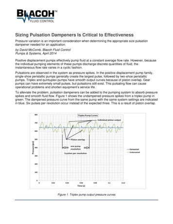
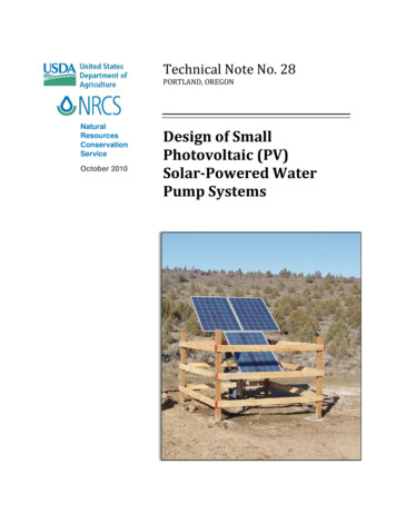
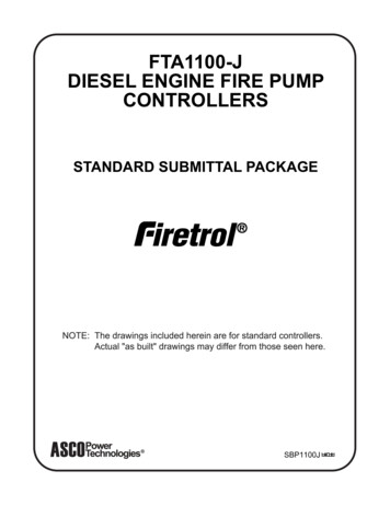
CSSM Cellular Suction Stabilizer Manifold PerformanceComparative performance of pressure in the Suction Manifold of a 5.5” X 14” Mud Pump isdisplayed for a WR Mattco CSSM060 Cellular Suction Stabilizer Manifold (ΔP 2 psi) versus aHydril C80 Suction Stabilizer (ΔP 120 psi) for one pump revolution with the pump operatingfrom 50 to 95 strokes per minute. The C80 was not installed correctly. The unit was mountedvertically with the inlet at the bottom and piped from the top to the standard pump suctionmanifold. The maintenance-free CSSM (Cellular Suction Stabilizer Manifold) performanceeliminates acceleration head loss and crosshead shock forces that can lead to power-endcrank and bearing failures as well as preventing hydraulic resonance in the suction piping. Byholding the pump suction manifold peak-to-peak hydraulic pressure variation to 2 psi, the potential for cavitation through the suction valves is significantly reduced.See Note AboveA7520Discharge peak hydraulic pressure variation in the Suction ManifoldPAGE 5REVISION 201504
Discharge Pulsation Control EquipmentWR Mattco Pulsation Dampeners are designed to stabilize the velocity variation of the mudpump. Proper sizing and setup is important to performance of the pulsation control equipment. The pipe shaking load (F) is equal to the peak-to-peak hydraulic pressure variation(ΔP) times the pipe cross section area (Ap). Location of the pulsation control equipment iscritical to its performance. Recommended location for the pulsation control equipment is within 6 times the nominal pipe diameter of the pump discharge manifold. Discharge dampenersare not effective when installed away from the pump.F A p PA7520 (20 Gallon Pneumatic Discharge Dampener with Nitrogen Charge)The 20 gallon pneumatic discharge dampener has been the drilling industrystandard for the past 50 years. Performance is based on its ability to storeand release fluid to reduce the velocity variation in the discharge piping system. The residual peak-to-peak pressure variation (ΔPg) is a function (GasLaws) of the pump volume variation (ΔVP) and discharge dampener nitrogenvolume (Vg) at operating pressure (P0). Pg PO POVgV g V pTwo A7520 (Pneumatic Discharge Dampeners with stepped Nitrogen Charge)Two pneumatic discharge dampeners with different charge pressures can be used to help reduce the velocity variation in the piping system but have significant operating limitations.Stepping the pre-charge is required for optimal performance, however operation at or nearthe dampener pre-charge pressures should be avoided as it may cause premature bladderfailure. It is recommended that if multiple dampeners are considered the optimal systemshould include a maintenance free dampener with a pneumatic dampener. While separatedampeners can be used the SP140M20 system is recommended due to its lighter weight andthe elimination of additional connections.SP140-7500CS (Liquid Maintenance-Free Discharge Dampener)The 140 gallon Liquid Maintenance-Free Discharge Dampener has beenused in the drilling industry for the past 14 years as an effective high pressure discharge dampener that does not require nitrogen charging or diaphragm replacements. Performance is based on its ability to store andrelease fluid to reduce the velocity variation in the discharge piping system. The residual peak-to-peak pressure variation (ΔPl) is a function ofthe pump volume variation (ΔV) divided by the fluid compressibility β (bulk modulus) and discharge dampener liquid volume (Vl) with a forced pressure drop (ΔPWB) at the outlet whereWave Blocker orifice coefficient (k) is multiplied by the fluid velocity (v).PAGE 6REVISION 201504
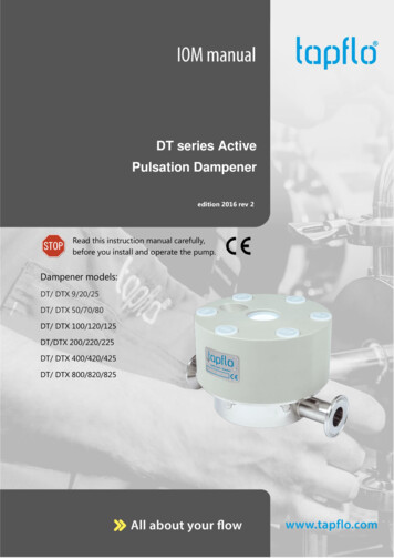
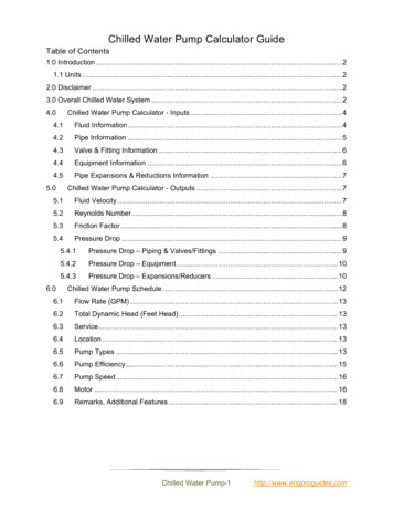
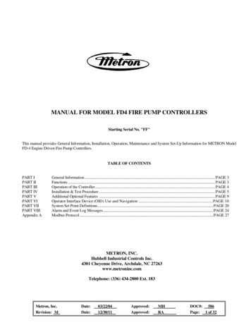
The unique advantages to the Liquid Maintenance-Free Pulsation Dampener is that all theparameters that determine performance remain constant over the entire pump operating pressure range. V2 Pl Vl PWB kvSP140M20-7500-SB Combination Dampener (Premium Low Maintenance)The SP140M20-7500 (U.S. Patent No. D626,819 ) is the combination ofthe Liquid Maintenance-Free and Pneumatic Discharge Dampeners intoa single unit. The same pressure pulsation dampening mechanism asdescribed in the Cellular Suction Stabilizer apply to the combination discharge dampener. Combination dampeners have proven to be effectivein preventing hydraulic resonance in discharge piping of Mud Pumps.Both types of dampeners reduce the residual pump flow variation. The in-line Liquid Maintenance Free Discharge Dampener is effective in reducing the amplitude of the acceleration pressure spikes and prevents themfrom going downstream to excite hydraulic or mechanical resonance.The following chart displays the actual performance during testing where hydraulic resonancewas occurring with an R120-7500. The addition of an A7520 eliminated the hydraulic resonance with the pump operating between 45 and 100 strokes per minute.Peak-to-peak hydraulic pressure variation in the Discharge ManifoldPressurePressureA7520Discharge DampenerR120-7500R120-7500 M20-7500100907545PAGE 7REVISION 201504
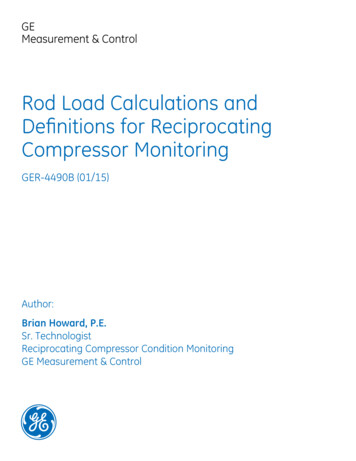
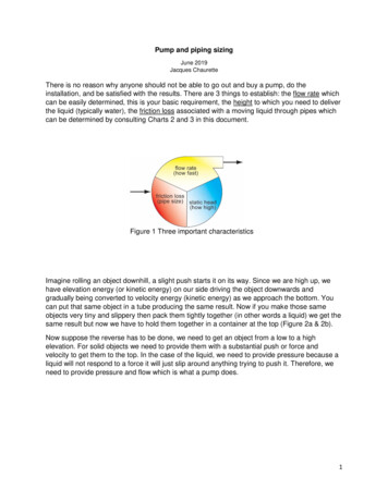
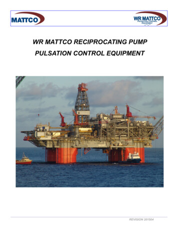
Anticipated Discharge Dampener Performance 5.5” X 14” TriplexA 14” Stroke Mud Pump with 5.5 inch liner delivers 454 gpm (1718 lpm) at 7475 psi (525.5kg/cm2) when operating at 105 strokes per minute. Traditional discharge dampener sizingcriteria for mud pumps has been to reduce the peak to peak pulsations below 3% of operatingpressure. This design criteria is inadequate with increased operating pressures and systemcomplexity. Experience has shown that if the peak-to-peak hydraulic pressure variation canbe reduced to below 80 psi mud pump fluid dynamic interaction will be minimized in the discharge piping.A7520 (Pneumatic Discharge Dampener with Nitrogen Charge)A single 20 gallon pneumatic discharge dampener has been used as the industry standardand experience has shown it can provide suitable performance in most systems at a reasonable cost. Pneumatic dampeners have some limitations when compared to maintenance freedampeners in that they have a more limited operating range and no dampening below thedampener charge pressure.Two A7520 (Pneumatic Discharge Dampeners with stepped Nitrogen Charge)Performance of two 20 gallon pneumatic discharge dampeners is marginal because of limited operating range and no dampening below the dampener nitrogen charge pressure. Inthe example of two pneumatic dampeners, there is potential damage to the diaphragm whenoperating near 2000 or 4000 psi.SP140-7500 (Liquid Maintenance-Free Discharge Dampener)The 140 gallon liquid volume discharge dampener will provide a maximum peak-to-peak hydraulic pressure variation of 97 psi over the entire operating pressure range. However, depending on mud pump discharge system configuration, hydraulic resonance can occur.SP140M20-7500 Combination Dampener (Premium)The SP140M20 is the integration of the Liquid Maintenance-Free and Pneumatic DischargeDampeners into a single discharge dampener. A Strainer/Wave Blocker can be installed onthe dampener outlet. The SP140M20 combination discharge dampener will provide a maximum peak-to-peak hydraulic pressure variation of 117 psi when operating below the nitrogencharge pressure and less than 73 psi when operating above.NOTE: In the following charts the A7520 pulsation dampener is labeled M20-7500PAGE 8REVISION 201504
Anticipated Discharge Dampener Performance 5.5” X 14” TriplexAnticipated Discharge Dampener Performance6005.5" X 14" SA Triplex550WR Mattco TargetM20-7500 @ 2000 psi500Two M20-7500 @ 2000 psi & 4000 psiPeak-to-Peak Pressure - psi450SP140-7500 Maintenance FreeSP140M20-7500 @ 2000 0350040004500500055006000650070007500Operating Pressure - psig454 Gallon per Minute at 105 Strokes per MinuteAnticipated Discharge Dampener Performance455.5" X 14" SA TriplexWR Mattco Target40M20-7500 @ 2000 psiTwo M20-7500 @ 2000 psi & 4000 psi35Peak-to-Peak Pressure - BarSP140-7500 Maintenance FreeSP140M20-7500 @ 2000 psi302520151050020406080100 120 140 160 180 200 220 240 260 280 300 320 340 360 380 400 420 440 460 480 500 520Operating Pressure - Bar1719 Liters per Minute at 105 Strokes per MinutePAGE 9REVISION 201504
Anticipated Discharge Dampener Performance 5.5” X 14” TriplexSingle M20 Pneumatic DampenerDual M20 Pneumatic DampenersPAGE 10REVISION 201504
Anticipated Discharge Dampener Performance 5.5” X 14” TriplexSP140 Liquid Maintenance Free Dampener including StrainerSP140M20 Combination Dampener including StrainerPAGE 11REVISION 201504
Anticipated Discharge Dampener Performance 7.5” X 14” TriplexA 14” Stroke Mud Pump with 7.5 inch liner delivers 843 gpm (3191 lpm) at 4025 psi (277.5kg/cm2) when operating at 105 strokes per minute. Traditional discharge dampener sizingcriteria for mud pumps has been to reduce the peak to peak pulsations below 3% of operatingpressure. This design criteria is inadequate with increased operating pressures and systemcomplexity. Experience has shown that if the peak-to-peak hydraulic pressure variation canbe reduced to below 80 psi mud pump fluid dynamic interaction will be minimized in the discharge piping.A7520 (Pneumatic Discharge Dampener with Nitrogen Charge)A single 20 gallon pneumatic discharge dampener has been used as the industry standardand experience
Hydril C80 Suction Stabilizer (ΔP 120 psi) for one pump revolution with the pump operating from 50 to 95 strokes per minute. The C80 was not installed correctly. The unit was mounted vertically with the inlet at the bottom and piped from the top to the standard pump suction manifold. The maintenance-free CSSM (Cellular Suction Stabilizer Manifold) performance eliminates acceleration head loss .