Transcription
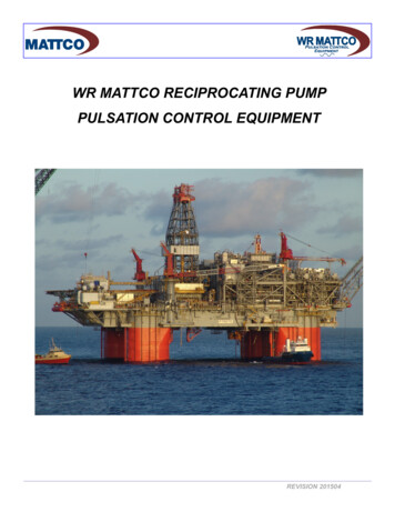
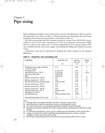
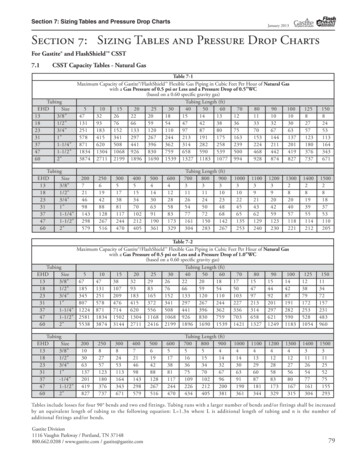
Sizing Pulsation Dampeners Is Critical to EffectivenessPressure variation is an important consideration when determining the appropriate size pulsationdampener needed for an application.by David McComb, Blacoh Fluid ControlPumps & Systems, April 2014Positive displacement pumps effectively pump fluid at a constant average flow rate. However, becausethe individual pumping elements of these pumps discharge discrete quantities of fluid, theinstantaneous flow rate varies in a cyclic fashion.Pulsations are observed in the system as pressure spikes. In the positive displacement pump family,single-shoe peristaltic pumps generally create the largest pulse, followed by two-shoe peristalticpumps. Triplex and quintuplex pumps have smooth output curves because of piston overlap. Gearpumps can have extremely small pulses, but pulsations still exist. This pulsating flow can causeoperational problems and shorten equipment’s service life.To alleviate the problem, pulsation dampeners can be added to the pumping system to absorb pressurespikes and smooth fluid flow. Figure 1 shows the undampened pressure spikes from a triplex pump ingreen. The dampened pressure curve from the same pump with the same system settings are indicatedin blue. Six pulses per revolution occur instead of the expected three. This is a result of piston overlap.Figure 1. Triplex pump output pressure curves
Determine Adequate SizeThe most common type of pulsation dampener is a hydro-pneumatic pressure vessel containingcompressed air or nitrogen and a bladder—or bellows—that separate the process fluid from the gascharge. To maximize the dampening effect, pulsation dampeners should be installed as close aspossible to the pump discharge with a gas charge that is slightly below the normal system pressure.More important, pulsation dampeners must be properly sized for the system.A dampener that is undersized cannot adequately compensate for pressure and flow fluctuations. Anoversized dampener will act as an accumulator, storing too much fluid. This will cause slow stabilizationand a delayed response to system changes. The first step in sizing a dampener is to quantitativelydefine the acceptable performance.Determine the Amount of Tolerable Pressure VariationThe specific requirements of the application and the components that make up the system are allfactors that need to be considered. Once an acceptable pressure variation is defined, the unit sizerequired for the desired performance should be determined. Engineers and designers are interested inmaking accurate predictions. Avoiding a problem is better than finding a way to fix it.Calculate Pressure FluctuationsSizing pulsation dampeners is straightforward. However, calculating the system pressure fluctuations ismore complex. Fluid discharge rates from pumps are difficult to mathematically model. For example, inFigure 1, the spikes are not even. Theoretically, they should be equal. Mathematical models must bephysically tested to verify their accuracy.Pumps with multiple heads and higher pulse frequencies can make the calculations more difficult. Thedistance from one output port to the next is generally not constant. This creates a shift in the pistonoverlap with intermittent larger and smaller pulses. Calculating the magnitude or frequency of noisepulses that can develop or resonate in a system is difficult.Piping arrangement—such as bends, reducers and valves—combined with the opening and closing ofpump discharge check valves can create noise in the fluid called pressure pulses. Because manyvariables must be considered, each pump type should be tested with and without a dampener. Thepressure curve data can be recorded and used to find the pump’s formula constant. This constant canbe used in future calculations. As long as other pump models are similar to the test unit, accuratelypredicting the magnitude of line pressure variation with a given size dampener is possible.Minimize Acceleration HeadThe pressure in a piping system will rise sharply when a volume of fluid is added to the line. Itaccelerates the mass of the fluid in the piping system. This is acceleration head, and it needs to beminimized with a dampener. The effect and its impact must be considered on both the inlets and outletsof positive displacement pumps. On the inlet side, cavitation and partial filling of pump cavities candamage pump components and make the pump much louder than normal.A non-snubbed pressure transducer can accurately measure the system’s pressure spikes. A pressuretransducer can react much faster than a bourdon tube gauge, and it can measure noise if the samplerate is high enough.Bourdon tube gauges require time to equalize and can undershoot and overshoot the actual pressuredepending on the magnitude and frequency of the pressure pulse. Even if the gauge could readaccurately, reading a quickly moving dial is difficult. Electronically measured and recorded data candetermine how the system is operating.System noise must be considered when taking measurements because it can give higher-thanexpected results. Noise in the pumping liquid can generally be ignored, but in some situations, systemnoise needs to be controlled. Noise can cause pressure relief valves to leak, damage sensitivecomponents and create occupational safety hazards. Dampeners typically reduce noise, and some arespecifically designed for this purpose.
Pulsation Dampener StylesSeveral different styles of dampeners are available, and each has advantages and disadvantages. Thisarticle focuses on reducing the pressure pulses caused by pulsing flow. The principles and the methodfor calculating the appropriate size dampener for this application are the same for most dampeners.A dampener absorbs a fluid pulse and then allows the fluid to flow back into the system betweenpulses. Most dampeners use a gas charge that is set slightly below the normal system pressure and iscompressed by the pulse of fluid. The gas then expands when fluid is released.Calculate Pressure ChangesTwo formulas should be considered when calculating pressure changes in the gas:If the pressure changes happen slowly, the gas temperature will have time to equalize. This is anisothermal process. The equation is:Where P1 and V1 are the initial states, and P2 and V2 are the final states.The other formula assumes no heat transfer from the gas to its surroundings. This is an isentropicprocess, and the equation is:( ).In this formula, n is a constant that is specific to the gas being used. For example, for air at roomtemperature,, and for nitrogen,.Some heat transfer almost always occurs. The process is rarely slow enough for the gas temperature toequalize, so the actual answer will be between these two calculations. In most cases, the fluctuationsare fast enough that the actual value is significantly closer to the isentropic formula. The isentropicformula gives the most conservative result. Therefore, it is the more accurate formula in most cases.In actual practice, either formula would probably work if the pressure fluctuations are small relative tothe system pressure. The pump constant that is developed would cover the inaccuracies in the formulaas long as the pressure variations are similar. In this article, the isentropic formula is used.Determine the Pump ConstantTo determine the pump constant, the volume from a single pulse of the pump must first be determined.Then an initial estimate of dampener size is made, and the corresponding value of dampener volume isapplied. The amount of gas in the dampener will be less than the total dampener volume, which needsto be factored into the calculation. A typical range of 80 to 90 percent of the dampener volume shouldbe gas if the dampener is properly charged. These give an initial gas volume:((()))The final volume is the initial gas volume minus the pulse volume:
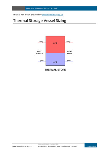
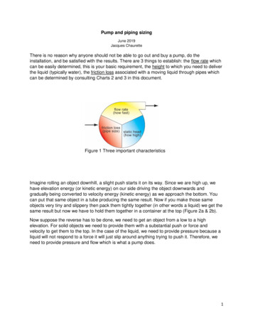
The constant reduces the pulse volume to account for flow leaving the dampener while the pulse isentering. It also accounts for piston overlap, which changes the effective size of the pulse. Adding thefactor to the isentropic formula and solving for the pump factor gives us the following equation:(( ) )Where:fd pump factor constantPa measured maximum absolute pressureP1 minimum absolute line pressureThe pressure formula can be rearranged to give the desired dampener volume with given minimum andmaximum pressures:( )(( ))The formula can also be rearranged to give pressure variation with the pump factor and with a knowndampener volume:()Note: The formula does not account for pressure spikes that result from rapidly changing the flow ratein the piping system. These pressure spikes, also known as water hammer, can travel throughout theentire piping system and may damage pumps, piping and other fixtures. If this type of pressuretransient occurs in the system, a larger dampener at the pump may be needed. Alternatively, anadditional dampener at the source of the transient spike may be required.For example, the pressure curve from an undampened, two-shoe, 2.5-inch peristaltic hose pump showsa sharp increase in flow, followed by a “no-flow” or negative flow zone. In this instance, the line has aball valve that is creating the flow restriction for back pressure. The blue line shows the undampenedpressure spikes (see Figure 2). The red line shows the pressure changes of the same pump with thesame back pressure valve setting but now using a dampener. This sample dampener has an actual gasvolume of 415 cubic inches, and the dampener is 90-percent gas filled. The base pressure is 14.15psig, and the pulse is 76.9 cubic inches. If the pressure fluctuation is calculated using the isentropicpressure formula, the result is:[((()))()]It is important to remember to add 14.7 psi to convert from gauge to absolute pressure, then subtract14.7 psi again to get the final result in gauge pressure. This pump setup was tested, and the actualpressure variation was determined to be 7.38 psi. Therefore, the result is:
Inserting the numbers into the factor formula gives:(())If the example above is used and it is decided that a pressure fluctuation of 15 psi would be acceptable,the formula with the previously calculated pump factor can be used to determine what size of dampeneris needed.((()))Figure 2. Peristaltic pump pressure curves
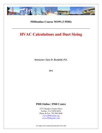
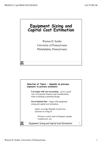
Table 1 lists some approximate pump constant factors thatcan be used when sizing dampeners for different pumptypes. These factors are approximate, and the results mayvary significantly with the many variables involved.Application 1A triplex plunger pump doses methanol, which is metered on the discharge side. Without a dampenerto control pulsations and smooth out the flow, the installed flow meters were giving inaccurate readings.When using a triplex pump, all three chambers of the pump must stay full of fluid with no voids. Anyvoids or pockets can cause seal leakage, pump vibration and excess pump noise.The solution was to install a pulsation dampener at the pump discharge to smooth the flow and removepressure pulsations. This allowed the dosing to be more accurate. An inlet stabilizer (suctiondampener) was also installed on the inlet side of the pump to act as an accumulator to keep the pumpchambers filled. The inlet stabilizer also removed pulsations created by the pump on its inlet stroke.Both devices were sized based on the pump type, flow rate and operating pressure.Application 2During the filling of a drum with a flexible hose, an automatic valve would close and cause a waterhammer effect. All the pipes leading into the system would shake until they broke loose from theirsupports. The solution was to install a pulsation dampener at the beginning of the flexible hoseconnection.The pulsation dampener was sized based on the flow parameters and installed at the beginning of theflexible hose. When the automatic valve closed, the hose and pulsation dampener effectively absorbeda portion of the water hammer, eliminating pipe shake and improving operational safety.ConclusionThe sizing of a pulsation dampener is critical to achieving the desired result. Finding and using thecorrect constant pump factor in dampener sizing is a key part of the solution. As long as the pulsationdampener is properly sized, positioned and charged, it will effectively dampen pulsations to protectequipment and keep the pressure pulses within design parameters.David McComb is the engineering manager at Blacoh Fluid Control, a manufacturer of pulsationdampeners, surge suppressors, inlet stabilizers and other fluid control products. McComb obtained aB.S. in mechanical engineering from University of California, Riverside, and has extensive experiencein project and product line management.BLACOH Fluid Control601 Columbia Ave, Bldg DRiverside, CA 92507 USA951.342.3100 or 800.603.7867Sales@Blacoh.comwww.Blacoh.comP47E11
The most common type of pulsation dampener is a hydro-pneumatic pressure vessel containing compressed air or nitrogen and a bladder—or bellows—that separate the process fluid from the gas charge. To maximize the dampening effect, pulsation dampeners should be installed as close as