Transcription
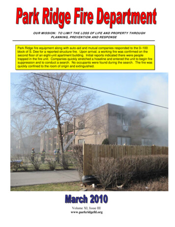
The Basics of Limit Switches
Table of Contents3-4Introduction.3Typical Limit Switch Applications.4Features and Benefits of Limit Switches.4Limitations of Limit Switches.4Limit Switch Terminology.5-7Limit Switch Styles.5Actuator/Operating Head.5Switch Body.5Receptacle/Terminals.5Standard Industrial Oiltight.6Precision.8-9Actuators and Operating Heads.8Rotary Lever Types.8Typical Levers.9Plunger Type Actuators.10-12Electrical Outputs.10Poles, Throws.10Snap Action vs. Slow Make-Break.10Electrical Ratings.11Polarity Observations.11Single Pole-Double Throw.12Double Pole-Double Throw.12Indicating Lights.12Low Energy Loads.13-14Receptacles.13Surface Mount Type.14Manifold Mounting Type.14Side Mounting Type.15-16Special Purpose Limit Switches.15Neutral Position Switches.15Two Step Switches.15Gravity Return Switches.16Guard Switches.17-18Cam Design Considerations.17Lever Arm Actuators.18Plunger Type Actuators.18Wobble Stick and Cat Whisker.19Mounting Considerations.20-22Appendix.2
Introduction: Limit Switch SensingPresence Sensing is the act of detecting the presence orabsence of an object with a contact or non-contact sensingdevice. The sensors then produce an electrical output signalthat can be used to control equip-ment or processes.Mechanical limit switches are contact sensing devices widelyused for detecting the presence or position of objects inindustrial applications. The term limit switch is derived fromthe operation of the device it-self. As an object (or target)makes contact with the operator of the switch, it eventuallymoves the actuator to the "limit" where the elec-tricalcontacts change state.Through this mechanical action, electrical contacts are eitheropened (in a normally closed circuit) or closed (in a normallyopen circuit). Inductive proximity, capacitive proximity, andphotoelectric sensors perform this same process through noncontact sensing.Typical Limit Switch Applications3
Features and Benefits of Limit Switches Can be used in almost any industrial environmentVery precise in terms of accuracy and repeatabilityConsume little electrical energyCan switch loads with high inductanceCan control multiple loadsLimitations of Limit Switches Generally restricted to equipment operating at relativelylow speeds.Must make direct contact with target.Moving mechanical parts will wear out.Limit Switch TerminologyPretravel — the distance or angle that the actuator must gothrough to trip the contactsOperating Point — position of the actuator at which thecontacts snap to the operated positionRelease Point — the position of the actuator at which thecontacts return to their original stateDifferential — distance (degrees) between contacts trip andcontacts resetOvertravel — movement of the actuator beyond thecontacts trip pointInitial Position — position of actuator when no external forceis ap-plied to the actuatorSome other important terms associated with limit switches:Operating force (torque) — force required to move theactuating elementMinimum return force (torque) — minimum force required toreturn actuator to its initial positionTotal Travel — the maximum allowable distance theactuating ele-ment can travelRepeat Accuracy — ability of a switch to repeat itscharacteristics precisely from one operation to the nextoperation4
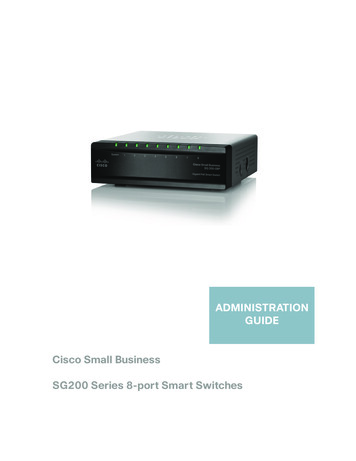
Limit Switch StylesMost limit switches contain the following functional parts in oneform or another.is due to the sensors having a long electrical and mechanicallifetime. These switches are designed so that the operatinghead, switch body and receptacle are separate components,as shown below.Actuator/Operating HeadThe actuator is the part of the switch which physically comesin contact with the target. In some limit switches, the actuatoris attached to an operating head which translates a rotary,linear, or perpendicular motion to open or close the electricalcontacts of the switch.Convenience is the advantage of the plug-in modular design.When installing a plug-in switch the user mounts thereceptacle to the fixture or machine it is to be used on. Thewiring is then brought into the receptacle through the conduitentrance on the bottom of the device. The wires areconnected to the terminals in the receptacle.The switch body then plugs-in to the receptacle and issecured with screws. The operating head is attached to thetop of the witch body with screws as well.Switch BodyThe component containing the electrical contact mechanism.Receptacle/TerminalsThe component containing the terminal screws orscrew/clamp assembly necessary for wiring purposes.While there are a number of different styles of limit switchesavailable in the market today, this manual will describe twoclasses of limit switches — standard industrial oiltight andprecision switches.Standard Industrial OiltightThe switch body can be quickly and easily replaced in the fieldwithout having to rewire the connections to the terminals in thereceptacle. The majority of new industrial applications todayutilize the plug-in design switch due to its superior sealing andruggedness.The classification standard industrial oiltight represents thoselimit switches which are most often the first choice forindustrial applications.These switches are designed to function in a variety ofindustrial environments where oil, grease, dirt, high pressurewashdown, shock or vibration are present. Typically thesedevices meet NEMA enclosure ratings of 1, 3, 3S, 4, 6, 11, 12,13 and possibly more. Some version meet IEC ratings such asIP66, IP67, etc. Most manufacturers offer models suitable forapplications from light to extremely harsh duty.Standard industrial switches are available in two configurations,plug-in and non plug-in. For most manufacturers, plug-in, ormodular limit switches, are represented as their heavy dutyapplication switch. This5
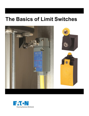
Hazardous Location Switches are another type of nonplug-in limit switch.Non plug-in switches differ from plug-in switches in that theswitch body and receptacle are one piece, as seen with thesensor below. The operating head is still a separate piece.These switches are designed to contain an explosion within theswitch itself. Hazardous location switches are usually providedwith four mounting holes and the cover is secured, using fourscrews. This device is much heavier and thicker in constructionthan standard oiltight switches.-The wiring in a non plug-in switch is brought in through theconduit entrance at the bottom of the body/receptacle. Thewiring terminals are accessible through the front of the switchby removing a cover plate. The cover plate is attached by twoscrews and contains a gasket on one side to provide a tightseal against the sensor.Even though the non plug-in design is somewhat outdatedmost manufacturers still offer them. It is also a popular designfor European DIN (Deutsch Industrie Norm) limit switches. DINswitches are built to meet dimensional and operationalstandards set in Europe.These sensors generally meet NEMA 1 requirements inaddition to the hazardous location requirements of NEMA 7Class I, Groups B, C and D as well as NEMA 9 Class II,Groups E,F and G. Some manufacturers do offer models ratedNEMA 4X, 13 as well. Like standard oiltight switches,hazardous location switches have removable actuatingheads which are attached to the switch body with fourscrews.PrecisionPrecision switches are widely used in both commercial andindustrial applications ranging from appliances to farmequipment. They are often chosen for their precise operatingabilities,
The actuator is the part of the switch which physically comes in contact with the target. In some limit switches, the actuator is attached to an operating head which translates a rotary, linear, or perpendicular motion to open or close the electrical contacts of the switch. Switch Body . The component containing the electrical contact mechanism. Receptacle/Terminals . The component containing .