Transcription
Hermetically Sealed, High Temperature Limit SwitchesHR Series003127Issue 1DatasheetFEATURES Exceptional wide temperature range of -65 C to 315 C[-85 F to 600 F] Select HR Series catalog listings are qualified or compliant toMIL-PRF-8805 Hermetically sealed to MIL-PRF-8805 symbol 5 Stainless steel housing and threaded bushing Different styles of integral actuators: pin plungers and rollerplungers Several different styles of electrical termination: 4-48 terminalscrews, end or side exit #20 AWG wire leadsPOTENTIAL APPLICATIONSDESCRIPTIONWhen the application requires a hermetically sealed switchwith high temperature capability, Honeywell delivers the HRSeries limit switches for the most severe of environments. TheHR Series is well suited for commercial and military aircraftapplications where high temperatures are encountered. Theswitch design incorporates a choice of an integral pin plungeror roller plunger with a 3/4 inch diameter threaded bushing forease of installation into a panel. With stainless steel materialconstruction for the external package and high temperaturerated components, the HR Series switches are capable ofwithstanding continuous temperatures up to 315 C [600 F] andsuitable where corrosive environments are present.HR Series limit switches are designed to MIL-PRF-8805standards with select catalog listings qualified to theMIL-PRF-8805 standards.VALUE TO CUSTOMERS Honeywell HR Series hermetically sealed high-temperatureswitches drive solutions for precise position indication ofcritical applications on commercial/military aircraft and militarysystemsSensing and Productivity Solutions Thrust reverser actuation system (TRAS) for jet engines Cowl-lock indication during thrust reverse actuation for jetenginesDIFFERENTIATION Only manufacturer with a bushing mount high-temperaturehermetically sealed limit switch Threaded bushing facilitates ease of installationPORTFOLIOIn addition to the HR Series hermetically sealed switches,Honeywell offers a complete range of sealed switches for aircraftand military systems. The sealed switches include the EN Series,HM Series, HE Series, HS Series, SE Series, and XE Series.
Hermetically Sealed, High Temperature Limit Switches, HR SeriesTable 1. using & bushing materialContactsCircuitryElectrical ratingMechanical enduranceElectrical enduranceDielectric strength (initial)Insulation resistance (initial)Environmental sealingTemperature rangeShockVibrationParameterHigh temperature hermetically sealed limit switch with MIL-PRF-8805 standardsDesign conforms to MIL-PRF-8805300 Series stainless steelSilver alloy1PDT or 2PDT [reference circuitry illustrations below]5 A resistive or 2 A inductive @ 28 Vdc25000 cycles min.25000 cycles min. at full rated load1000 VRMS; 500 μA. Max. leakage500 Vdc; 1000 Megohms min.Symbol 5, hermetic seal per MIL-PRF-8805-65 C to 315 C [-85 F to 600 F]Symbol M (100 g) per MIL-PRF-8805Symbol 1 (10 g peak) 10 Hz to 500 Hz sinusoidal per MIL-PRF-8805TYPICAL CIRCUITRY1PDT2PDTHR SERIES SWITCHESThe HR Series high-temperature hermetically sealed switches aredesigned with a threaded bushing for panel mount applications.The HR Series has a threaded bushing which is 0.75 (3/4) indiameter.The options for the electrical termination for the HR Seriesswitches are generally end exit wire leads or screw terminalsintegral to the switch; however, military style connectors integral tothe HR switch are also available.2PDT with connectorFAEMOUNTINGPlunger actuator switches bushing mount through 0.75 inch(19,1 mm) diameter holes. Lock washer, keying washer, and wirelock hexagon mounting nuts lock the switches in their mounting.ACTUATORSPlungerFor in-line actuation. An ice scraper ring clears the actuator witheach operation. Material is stainless steel.Roller plungerFor cam and slide actuation not to exceed 20 rise. Roller adjustslaterally in 45 increments. An ice scraper ring cleans theactuator with each operation. Material is stainless steel.2sensing.honeywell.comBCD
Hermetically Sealed, High Temperature Limit Switches, HR SeriesELECTROMECHANICAL SWITCHESDefinitions below explain the meaning ofoperating characteristics. Characteristicsshown in tables were chosen as mostsignificant. They are taken at normal roomtemperature and humidity. These may varyas temperature and humidity conditionsdiffer. Sketches show how characteristicsare measured for in-line plunger actuation.Linear dimensions for in-line actuation arefrom top of plunger to a reference line.Differential Travel (D.T.) – Plunger oractuator travel from point where contacts‘‘snap-over’’ to point where they ‘‘snapback.’’Free Position (F.P.) – Position of switchplunger or actuator when no external forceis applied (other than gravity).Full Overtravel Force – Force required toattain full overtravel of actuator.Operating Position (O.P.) – Position ofswitch plunger or actuator at which pointcontacts snap from normal to operatedposition. Note that in the case of flexible oradjustable actuators, the operating positionis measured from the end of the lever orits maximum length. Location of operatingposition measurement shown on mountingdimension drawings.Operating Force (O.F.) – Amount of forceapplied to switch plunger or actuator tocause contact ‘‘snap-over.’’ Note in thecase of adjustable actuators, the forceis measured from the maximum lengthposition of the lever.Overtravel (O.T.) – Plunger or actuatortravel available beyond operating position.Pretravel (P.T.) – Distance or angletraveled in moving plunger or actuator fromfree position to operating position.Release Force (R.F.) – Amount of forcestill applied to switch plunger or actuatorat moment contacts snap from operatedposition to unoperated position.Total Travel (T.T.) – Distance from actuatorfree position to overtravel limit position.Sensing and Productivity Solutions3
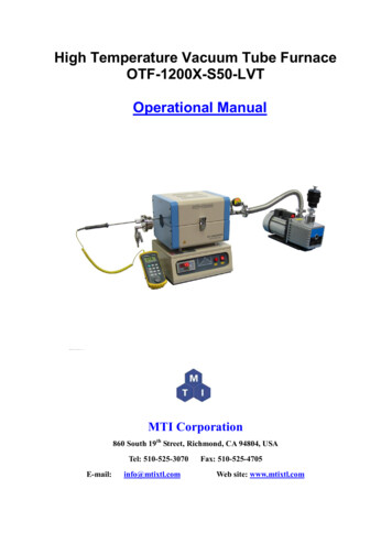
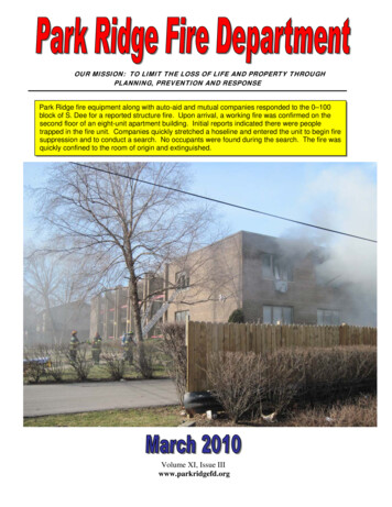
Hermetically Sealed, High Temperature Limit Switches, HR SeriesTable 2. Order GuideCircuitryCatalog ListingMilitary Numberor NoteElectricalTerminationOperating ForceN [lb]Release Forcemin. N [lb]Free Positionnom. mm [in]Pretravel max.mm [in]Overtravel min.mm [in]Differential Travelmax. mm [in]Bushing ThreadHousing Heightmax. mm [in]Housing Diameternom. mm [in]DimensionalActuatorSwitch s (6), #4-4826,7 to 53,4[6 to 12HR8-6–Leadwire #20 AWG (endexit) per MIL-C-2503826,7 to 53,4[6 to 2PDT22HR1-S–Screws (6), #4-4826,7 to 53,4[6 to PDT22HR8-6–Leadwire #20 AWG (endexit) per MIL-C-2503826,7 to 53,4[6 to 2PDT22HR80-RB-31 C to 204 C [-25 F to400 F]6-pin, end-exitconnector26,7 to 53,4[6 to 015]0.750-20UNEF76,2[3.0]26,9[1.06]PRODUCT DIMENSIONSFigure 1. 12HR1-S mm [in]Ø 25,4[Ø 1.0]13,41[0.528]Ø 9,53[Ø 0.375]Steel plungerRoller guide lock ring42,55[1.675]1,19 [0.047]hole for wirelocking33,02[1.3]Hex nut1,27[0.05]Internal tooth lock washerKeying washer3/4-20 UNEF thread to within3,81 [0.150] of shoulder1,83 wide x 1,24[0.072 wide x 0.049]keyway to within[0.25] of shoulder38,1[1.5] max.231144-48 NF-2A X 0.188 refpan head terminal screwsand washers (SEMS)2,54[0.10] max.4sensing.honeywell.com
Hermetically Sealed, High Temperature Limit Switches, HR SeriesFigure 2.12HE8-6 mm [in]Ø 26,92[Ø 1.06]13,41[0.528]Ø 9,53[Ø 0.375]Steel plungerRoller guide lock ring42,55[1.675]33,02[1.3]Hex nut1,27[0.05]1,19 [0.047]hole for wirelockingInternal tooth lock washerKeying washer3/4-20 UNEF thread to within3,81 [0.150] of shoulder1,83 wide x 1,24[0.072 wide x 0.049]keyway to within[0.25] of shoulder60,96[2.4] max.(3) No. 20 wire lead perspec MIL-C-25038 marked,per spec MIL-W-5088(1-20, 2-20, 3-20)1828,8[72.0] max.Figure 3. 22HR1-S mm [in]Roller guide may be lockedin increments of 45 azimuth.Roller guide may be unscrewedand removed from bushing tofacilitate installation.Ø 25,4[Ø 1.0]Ø 22,1[Ø 0.87]13,41[0.528]Ø 15,88[Ø 0.625]54,36[2.14]Ø 12,7 x 4,6 wide[Ø 0.5 x 0.18 wide]steel rollerRoller guide lock ring21,08[0.83] 11,94[0.47]1,19 [0.047]hole for wirelocking1,83 wide x 1,24[0.072 wide x 0.049]keyway to within[0.25] of shoulder24,64[0.97]231Hex nut1,27[0.05]Internal tooth lock washerKeying washer3/4-20 UNEF thread to within3,81 [0.150] of shoulder38,1[1.5] max.144-48 NF-2A X 0.188 refpan head terminal screwsand washers (SEMS)2,54[0.10] max.Sensing and Productivity Solutions5
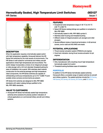
Hermetically Sealed, High Temperature Limit Switches, HR SeriesFigure 4. 22HR8-6 mm [in]Roller guide may be lockedin increments of 45 azimuth.Roller guide may be unscrewedand removed from bushing tofacilitate installation.Ø 26,92[Ø 1.06]Ø 22,1[Ø 0.87]13,41[0.528]Ø 15,88[Ø 0.625]54,36[2.14]21,08[0.83] 11,94[0.47]24,64[0.97]Ø 12,7 x 4,6 wide[Ø 0.5 x 0.18 wide]steel rollerRoller guide lock ring1,19 [0.047]hole for wirelockingHex nut1,27[0.05]Internal tooth lock washerKeying washer3/4-20 UNEF thread to within3,81 [0.150] of shoulder1,83 wide x 1,24[0.072 wide x 0.049]keyway to within [0.25] of shoulder60,96[2.4] max.(3) No. 20 wire lead perspec MIL-C-25038 marked,per spec MIL-W-5088(1-20, 2-20, 3-20)1828,8[72.0] max.Figure 4. 22HR80-RB mm [in]Ø 26,9 [1.06]Roller guide may be lockedin increments of 45 Azimuth.Roller guide may be unscrewedand removed from bushing tofacilitate installationØ 22,1 [0.87]Ø 15,88 [0.625]21,1[0.83]54,4 [2.14]Free position13,5 [0.53]Ø 12,7 [0.5] x 4,6 [0.18] wide stainless steel rollerRoller guide lock ring11,9[0.47]Ø 1,19 [0.047]Hole for wire locking24,6 [0.97]1,3 [0.05]2X Hex nut 23,8 [0.94] across flats x 3,0 [0.12] thickInternal tooth lock washer. Ø 26,9 [1.06] x 0,56 [0.022] thickKeying washer, Ø 24,9 [0.98] x 0,079 [0.031] thick,tab 2,8 [0.11] wide0.75-20 UNEF thread to within 3,8 [0.15] of shoulder76,2 [3.0] max.FPhysical science connectorHP02WS-14S-6P (Type) (or equiv)AEBCDConnector(bottom view)6sensing.honeywell.com
m WARNINGADDITIONAL MATERIALSThe following associated literature is available on the Honeywellweb site at sensing.honeywell.com: Product installation instructions Aerospace range guidePERSONAL INJURYDO NOT USE these products as safety or emergency stopdevices or in any other application where failure of the productcould result in personal injury.Failure to comply with these instructions could result indeath or serious injury.m WARNINGMISUSE OF DOCUMENTATION The information presented in this product sheet is forreference only. Do not use this document as a productinstallation guide.Complete installation, operation, and maintenanceinformation is provided in the instructions supplied witheach product.Failure to comply with these instructions could result indeath or serious injury.Warranty/RemedyFind out moreHoneywell serves its customersthrough a worldwide networkof sales offices, representativesand distributors. For applicationassistance, current specifications, pricing or name of thenearest Authorized Distributor,contact your local sales office.To learn more about Honeywell’sHoneywell warrants goods of its manufacture as being freeof defective materials and faulty workmanship. Honeywell’sstandard product warranty applies unless agreed to otherwise byHoneywell in writing; please refer to your order acknowledgementor consult your local sales office for specific warranty details. Ifwarranted goods are returned to Honeywell during the period ofcoverage, Honeywell will repair or replace, at its option, withoutcharge those items it finds defective. The foregoing is buyer’ssole remedy and is in lieu of all other warranties, expressedor implied, including those of merchantability and fitness fora particular purpose. In no event shall Honeywell be liable forconsequential, special, or indirect damages.While Honeywell may provide application assistance personally,through our literature and the Honeywell web site, it is up tothe customer to determine the suitability of the product in theapplication.Specifications may change without notice. The information wesupply is believed to be accurate and reliable as of this printing.However, we assume no responsibility for its use.sensing and control products,call 1-815-235-6847 or1-800-537-6945,visit sensing.honeywell.com,or e-mail inquiries toinfo.sc@honeywell.comHoneywell Sensing and Productivity Solutions9680 Old Bailes RoadFort Mill, SC 29707honeywell.com003127-1-EN IL50 GLOJuly 2016 2016 Honeywell International Inc. All rights reserved.
spec MIL-C-25038 marked, per spec MIL-W-5088 (1-20, 2-20, 3-20) Figure 4. 22HR80-RB mm [in] Ø 26,9 [1.06] Roller guide may be locked in increments of 45 Azimuth.