Transcription
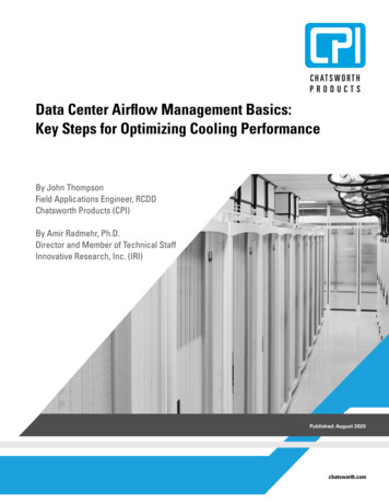
International Journal of Thermal TechnologiesE-ISSN 2277 – 4114Available at http://inpressco.com/category/ijtt/ 2015INPRESSCO , All Rights ReservedReview ArticleAirflow Management in Automotive Engine Cooling System - OverviewBaskar S†* and Rajaraman R‡†Mahindra‡DeptResearch Valley, Chennai, Indiaof Mechanical Engineering, B. S. Abdur Rahman University, Chennai, IndiaAccepted 10 Feb 2015, Available online 01 March2015, Vol.5, No.1 (March 2015)AbstractEngine cooling system plays a vital role in improving the vehicle fuel economy and meeting the stringent emissionnorms apart from maintaining the operating temperature of engine. The airflow through vehicle subsystems like thegrille, bumper, hood-latch baffles, the heat exchangers, the fan and shroud is called as front-end flow. Front end flow(Underhood air flow) is crucial factor in engine cooling system as well as in determining the aerodynamic drag ofvehicle. This paper discusses the front end flow rate prediction, factors influencing the front end flow and its influenceon vehicle drag. Further the trends in the aerothermal management in order to improve the front end flow andvehicle performance also discussed.Keywords: Engine cooling system, Front End Flow, Cooling drag, Airflow circuit, Fan, Radiator1. Introduction1 Theairflow through vehicle subsystems like the grille,bumper, hood-latch baffles, the heat exchangers suchas condenser and radiator, the fan and shroud is calledas front-end or underhood or cooling air flow (Fig.1).The amount of airflow through the enginecompartment is determined by the front end vehiclegeometry, the cooling system package and the enginecompartment geometry including the inlet and outletsections. The airflow in the underhood is driven byfan/ram air. During idling condition fan is the mainsource and in vehicle running condition ram air is themain source for driving air. However this will changewith respect to vehicle speed.Fig.1 Front End Flow*Corresponding author: Baskar SThe knowledge of airflow through underhood withrespect to the engine cooling system becomes moreimportant recently. The necessity of this kind of studyfrom various researchers’ aspect as follows The objective of cooling airflow subsystem is toachieve the required heat exchanger air mass flowrate, with minimum power consumption whilemaintaining aerodynamic drag and noise withinvehicle NVH target (Peter Kanefsky et al 1999, Huet al 2011) No link established between the airflow uniformitythrough the heat exchanger and cooling drag (DHondt et al 2011) The interaction between underhood airflow andexternal aerodynamics is not yet fully understood(D Bader et al 2011) The influence and impact of cooling flow rates arenot studied and configurations favorable to enginecooling are undetermined. (Marion D Hondt et al,2011) Increase in air velocity has much impact on theoverall heat transfer coefficient than the effect dueto increase in mass flow rate of coolant ( Naraki etal 2013, Karthick et al 2012) Thus for optimum design of cooling system,subjects to be studied to ensure satisfactoryperformance are Heat exchanger and airflow(Masatoshi et al 1993). Much detailed reviewavailable on Heat exchanger development (R. K.Shah 2003, Josef kern and JochenEit el 1993, L.P.Saunders 1936).The above facts delineates a clear path towards thedevelopment of airflow management in engine coolingsystem is essential in the automotive systems.1 International Journal of Thermal Technologies, Vol.5, No.1 (March 2015)
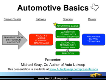
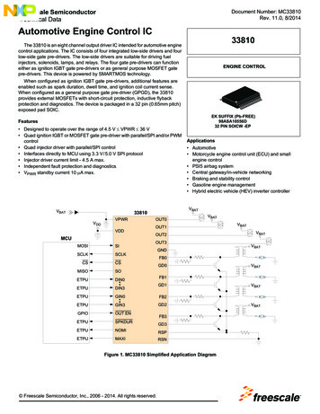
Baskar S et alAirflow Management in Automotive Engine Cooling System - OverviewThere are reviews available on engine cooling system(S C Pang et al 2012, H H Pang et al 2004). Khaled et al2014 reviewed the influences of componentsarchitectural arrangement on aerothermal behavior inthe underhood compartment. In automotive systemsenergy consumption, management and recovery hasbeen reviewed by fabiochiara et al 2013 focusing onconventional powertrain. Still it lags a clear picture onfront end flow rate prediction, factors influencing frontend flow and aerothermal management in automotivesystems.Objective of this work is to develop anunderstanding of airflow management with respect tothe engine cooling system as well as opportunities andpotential challenges in improving the front end flowand vehicle performance. Recently Wamei Lin andBengt Sunden 2010 reviewed the importance of vehicleengine cooling system(ECS) for reducing fuelconsumption and Carbon dioxide. Impact of ECS onvehicle cost reduction was discussed by Neal A. cook1972, Michael sortor 1993.This paper has been arranged in the following way.First it discusses the current status on airflowmanagement in the engine cooling system focusing on–front end flow rate prediction, factors influencing thefront end flow and its influence on vehicle drag. Thencurrent, past and future trends in the aerothermalmanagement of underhood components in order toimprove the front end flow and vehicle performancefollowed by conclusion.2. Front End Flow rate predictionThis section discusses about finding out the front endflow rate in automotive using CFD tools andexperimental methods. The various modelingtechniques and measurement methods are discussedhere.2.1 CFD analysisFor a vehicle the required amount of front end flowrate can be predicted with the help of operating point.Operating point is defined as Intersection of the systemresistance curve and the fan performance curve (Fig.2).System resistance curve represents the total pressuredrop in airflow from the grille entrance area to exitregion of vehicle. Fan performance curve representspressure rise vs flow rate of a particular fan. CFDmodeling, can be used to predict system and fanresistance curve.(Damodaran et al 2003,Shigarakanthi et al 2011, Dube et al 2007,SadekRahman et al 2010, Regin et al 2014)Mostly CFD tools used to predict the front endairflow rate. In CFD modeling, the obstructions in theairflow path from grille entrance area to exit areaneeds to be captured as it’s in real vehicle.The vehicle domain and the flow domain size playsa major role in front end flow rate prediction. (K DHuang et al 2004). The recommended guideline forflow domain as followsFig.2 Predicting operating point using systemresistance and fan performance curveFrom the sides and above vehicle model: fivecharacteristic length.In front of the bumper: Eight characteristic length.Behind vehicle domain: four characteristic length.(Characteristic length is the distance between thebottom of the vehicle to the top of vehicle domain)The various flow resistances in enginecompartment and modeling techniques of the variousunderhood components as follows2.1.1 Perforated inlets: Sudden expansion andcontraction leads to losses at perforated inlets.Momentum sinks are calculated and included in themomentum equations (sami et al 1994). Rosberry1990 studied on the grille coefficient. They defined thegrille coefficient as a fraction of free stream totalpressure which is delivered through grille.2.1.2 Radiator core: The radiator was modeled usinglumped blockage approach and average porosity factorused throughout the radiator (sami et al 1994).Hur et al 2009 proposed Semimicroscopic heatexchange (SHE) method. SHE method was employed todo conjugate heat transfer analysis in the regions ofcoolant water in a tube, tube wall, louver fin andambient air. The louver fin region has been separatedinto air and solid porous media. The temperaturedifference in between these two porous mediadetermines the local heat flux. The obtained results arein good agreement with experimental results. SangHyuk Lee et al 2014 proposed further modification inSHE method.2.1.3 Fan modelingThe various methods available for fan modeling asfollowsa) Body Force ModelThis model also known as Lumped Fan model. In thismodel fan characteristics represented rather thanmodeling the geometry of the fan blades. Theexperimental results of fan blade characteristics curveare represented as Pressure Jump boundary conditionin CFD analysis. The accuracy of this model dependsupon the fan blade characteristic curve. (Wang et al2005, Sami et al 1994)2 International Journal of Thermal Technologies, Vol.5, No.1 (March 2015)
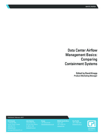
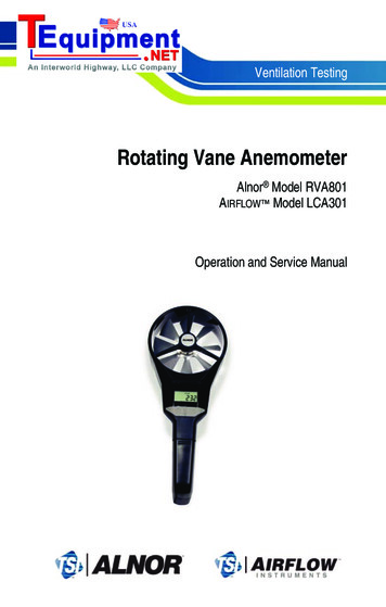
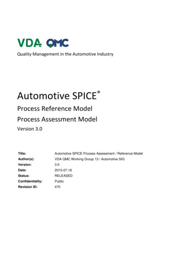
Baskar S et alAirflow Management in Automotive Engine Cooling System - OverviewTable 1 Overview of various flow measurement methods (Ng et al 2004) E-excellent, M-moderate, pressure implicityof useAccuracy,volumeflow rateAccuracy,airflowdistributionSuitable foron PPPMEPEPEEPEPPP(HWA - Hot Wire Anemometry, HFA - Hot Film Anemometry, LDA - Laser Doppler Anemometry, PIV - Particle Image Velocimetry)b) Multiple Reference Frame (MRF) ModelIn this model the geometry of fan blades arerepresented. No need to depend on the experimentalresults of fan blade characteristic curve. The fluid zoneof fan region is modeled as rotating frame and thesurrounding zones are modeled as stationary frame.(Wang et al 2005). MRF model is a steady stateapproximation.c) Sliding Mesh ModelAs the rotor stator interactions are time-periodic thefan modeling requires the flow to be solved in transientmethod. This method very time consuming whichmakes it impractical for industrial application. (Wanget al 2005)A brief discussion on the fan modeling methodsdiscussed by sami et al 1994, H. Knaus et al 2005. Morefan modeling research is needed in the area of fanresistance and radial flow to make the model moresuitable. Mostly MRF model is used in underhood flowsimulation.The front end flow rate can be predicted with twodimensional computation domain. (Jongsoo et al 1993,kazuo kawashima et al 1988)2.2 Experimental underhood system is a challenging task. Butthe knowledge of airflow distribution anddetermination is a key factor in determining the moresuitable front-end configuration for the coolingcapacity as well as aerodynamics.The various methods available for airflowmeasurement and its merits and demerits are shown inTable-1. The various available literature are (RickRuijsink et al 1993, Helmut et al 1993, E Y Ng et al2004).3. Factors influencing the front end flowThis section discusses the factor which influences thefront end flow and the required operating condition offront end flow. Different people categorized in differentway.The engine compartment is fully occupied with thelot of components which acts as obstruction in theairflow passage. Refki EI-Bourini 1993 studied on theinfluence of front end components on vehicle enginecompartment air flow.Olson 1976 studied the aerodynamic effects of frontend design on automobile engine cooling systems. Theinfluences of the bumper, grille, air dam, fan andshroud were clearly noticed. The various factors whichinfluences the front end flow rate from the differentresearchers aspect as follows.There are four major contributions to the air sidesystem resistance in automotive cooling system. Theyare front end resistance, engine blockage, engine bayexit path loss and engine bay back pressure due tovehicle motion. Detailed list as shown Fig-3 (U NSchaub and H N Charles 1980)The parametric diagram for cooling airflowsubsystem as per Peter Kanefsky et al 1999Unwanted Engine heatAirflow subsystemAirmass flow rateThe control factors are system resistance, fangeometry, fan speed, fan tip clearance, protrusion offan shroud, fan shroud geometry.The side effects arefan power consumption, fan noise, and aerodynamicdrag.3 International Journal of Thermal Technologies, Vol.5, No.1 (March 2015)
Baskar S et alAirflow Management in Automotive Engine Cooling System - OverviewFig.3 system resistance chart(U N Schaub and H N Charles 1980)The parameters that characterize the air circuit of anengine cooling systems as per A Costelli et al 1980, System resistance actual fan performance and its coupling withsystem aerodynamic efficiency of air intake (ratio ofaverage air velocity through radiator and vehiclespeed)Significance of the parameters which affectsunderhood air flow with respect to engine coolingsystem are classified as follows. (Taylor et al 1976).Fan characteristics, Projection of fan into shroud Highly significant parameter.Fan to radiator distance, radiator characteristics, andfan tip to shroud clearance - Significant parameters.Fan to engine block distance and type of shroud - Notsignificant parameter.It is to be noted that type of shroud is notimportant, but shroud to be used to maintain areasonable tip clearance. It has been shown that shapeof the fan shroud can be of great importance for somecases and not in some other. But the depth of shroud ismost critical parameter. Increasing the depthinfluences both mass flow and uniformity. Fanprojection into the shroud influences the performanceof fan. (Thomas Hallqvist 2008, X Hu et al 2011)The recommended operating conditions of frontend air flow as follows (Hoshino et al 1981)a. Cooling airflow rate: As high as possible. But to beoptimized in such a way to reduce the drag.b. The turbulence of cooling airflow: As low aspossible.c. The cooling airflow distribution on the radiatorfront: Uniform. Influence of flow distribution onradiator has been addressed by other researchersalso.(Esmeili et al 2010, Tomasz Bury 2012,Ng et al2005, WaiMeng Chin 2013, M Khaled et al 2011, Olietet al 2007)d. The cooling airflow leakage at radiator front: To beminimized.The influence of air flow leakage in the enginecompartment discussed separately by M Khaledet al2014.Still the influence of blade thickness on the fanperformance is a open question. (C Sarraf et al 2011)4. Front end flow and dragThis section discusses on cooling drag and factorswhich influences cooling drag mainly front end flow.The cooling drag coefficient in wind tunnel is evaluatedby measuring the aerodynamic drag of vehicle withopened and then closed air inlets. In old cars (1970 1980 era) the cooling drag contribution is around 0.04counts (Hucho 1998). The contribution of cooling draginto the total drag generally varies from 5% to 10%.4 International Journal of Thermal Technologies, Vol.5, No.1 (March 2015)
Baskar S et alAirflow Management in Automotive Engine Cooling System - Overview(Barnard 2000). The area and resistances offered bycooling air inlet, outlet and heat exchanger are themain drag contributors.Increasing the cooling air inlet area beyond acertain value does not change the cooling mass flowwhereas increases the cooling drag. (D Baeder 2011,2013)It was found that the location of air outlet alsoinfluences the cooling drag. Cooling airflow outletlocated at the base of geometry favors low cooling dragvalue compared to an outlet located in the underbody.(Hondt and Gillerion 2011). Air exiting the wheelhouse has much contribution to the cooling drag. (DBaeder et al 2013). The relation between aerodynamicdrag of radiator with cooling air flow was reported asnonlinear. (Petrov 2008)5. Current, Past and Future trends in Front EndFlow managementThe Grille opening area, Heat exchanger and fan are thekey players for better air flow management. Thissection outline the existing, past and futuretechnologies on these things.5.1 Grille Opening AreaOpenings in front of the radiator through which airenters into the vehicle front end is called as Grille Openarea (GOA) or front end opening area. This areadetermines the amount of air entry into the enginecompartment. GOA also plays a role in temperaturestabilization of underhood components. HoweverTanjuSofu et al 2004 observed that underhoodtemperatures are stabilized near an air flow ratio of 2.The ventilation air flow rate was normalized withrespect to engine combustion flow rate.It was shown that upto 13.5% reduction in dragvalue of vehicle could be attained by closing the GOA(MIRA report). The GOA should be in such a way that itallows the optimal ram air only which meets thefunctional requirement of respective system.Reduction in the unnecessary ram air entry into theengine compartment can be done by the optimizing thesize and location of GOA.The various criteria which has been used to fix theGOA as follows Basically the GOA is based on the rule of thumb orprojected radiator area design standards. Front end opening ratio (open area of front enddivided by radiator area) of approximately 30% isdesirable to meet the styling requirements (Kazuokawashima and Fugi 1988). The recommended arearatio between inletsection of grille and frontal surface of radiator is0.4 (Ngy et al 2002) Jack Williams 1985 proposed a performance basedapproach to fix the GOA. It is expected that largeGOA provides huge air flow. But in reality it wasobserved that GOA is not a very good predictor ofcooling air flow, specifically at 30 mph gradecondition. They established a statistical relationbetween grille open areas, drag and ram airflow. Smaller front grille opening and large enginecooling fan will favor the fuel economy. It’smentioned that this is not a general guideline forvehicle development. (Bing Xu et al 2013) Vehicle system resistance curve and coolant inlettemperature are used to optimize the front grilleopening area (Regin et al 2014)Various configurations of grille and front end intakegeometries of a passenger car were investigated withrespect to mass flow and mass flow distribution onengine cooling components (Knaus et al 2005, MyungSeokLyu et al 1996)Four different shielding methods were employed todetermine best among them. The shielding methodswere vertical, horizontal, side-to-side and side-tocenter. It was observed that the best method ofshielding would be horizontal method followed byvertical method. More uniform airflow distributionobtained in horizontal method compared to others.(Jama et al 2004)S. D. Oduro 2012 assessed the effect of blockage offront end air flow with respect to the coolant inlet andoutlet temperature. It was observed that percentagearea covered resulted in the increase of coolant inletand outlet temperature.As the GOA to be based on the performanceoriented rather than based on thumb rule. And it needsa lot of study on engine compartment components tomeet the airflow requirement. With the advancedtechnology there is a concept called Active Grilleshutter system, which opens and close the grilleautomatically.5.1.1 Active grille shutter system (AGS)The shutters open and close automatically to controlairflow, reduce aerodynamic drag and by the wayimproves the fuel efficiency. The car manufacturersusing active grille shutters include General Motors,Chrysler, BMW, and Honda.Shigarkanthi et al 2011 studied the application ofdesign of experiments and physics based approach inthe development of aero shutter control algorithm.Active aero shutters are devices that control theairflow through heat exchanger module to optimize thebalance between aerodynamic drag and engine cooling.The predictive algorithm of aero shutter predicts thecooling need of the system and actuates the enginecooling fan and shutter to different position to meet thereal time cooling requirement.There is a reduction in the fuel economy up to 2.6%(Rashad Mustafa et al 2012). AGS provides reduced airresistance as well as reduction in engine loss (ElSharkawy et al 2011)5.2 Heat ExchangerThe heat exchanger (Radiator) position, performanceand its material plays a crucial role in offeringresistance to the airflow path.5 International Journal of Thermal Technologies, Vol.5, No.1 (March 2015)
Baskar S et alAirflow Management in Automotive Engine Cooling System - OverviewWith improved heat exchanger performance there is ascope to minimize the requirement of the airflow. Thedistance between the radiator and engine block will beadjusted automatically to increase heat exchangersevacuation capacity in situations during engine overheat condition. It was observed that increase in heattransfer performance of radiator about 18% at fan lowspeed and 7% at high speed (Khaled et al 2012). Thishelps in reduction of compressor and pump workwhich ultimately reflects in vehicle fuel consumption.The heat exchangers like condenser, Radiator andCharge Air Cooler are located behind the grille offersresistance to the airflow. Especially the arrangementone behind the other increases the resistance. It wasfound that by placing them in parallel the overallthermal performance improved by 4.4% and 0.9% ofpressure losses were eliminated (Khaled et al, 2011)It was proposed that placing a heat exchanger at theroof of the heavy vehicle driver compartment(countercurrent flow) could be a good option. (WameiLin et al 2012) With increased power requirement andunderhood space requirement in vehicle, acountercurrent heat exchanger was proposed on theroof of vehicle.Recently enormous study available on theperformance of radiator using nano materials ascoolant. And it resulted in considerable enhancementin thermal performance and reduction in frontal areaof radiator (Leong et al 2010). Shanti et al 2012conducted a detailed review on the application of nanomaterial and its limitation. Kim et al 2010 has done astudy on radiator performance using Phase changematerial as a coolant.Another efficient method to increase the thermalperformance of heat exchanger is the utilization offoam materials. The graphite foam fin has higher heattransfer coefficient than aluminum. It is to be notedthat this method is preferable in application wherereduced heat exchanger volume is favored overreduced mass or COP (Wamei Lin et al 2014). But thepressure drop through graphite foam is huge. And itwas concluded that there are still several problems indeveloping the application of graphite foam heatexchanger in vehicle. (Patrick et al 2010)R. J. Gaeta 2004 evaluated aerodynamic heatexchanger. A 2D wing was fabricated and radiator corewas integrated into it. Three different materials wereinvestigated: Aluminum finned, dense carbon-graphitefoam material, smaller carbon-graphite foam fins. Thisdevice has low drag and Carbon-graphite foam showsoptimal performance. However Pneumatic system andcoolant pump size are the concerns forcommercialization.5.3 FanFan could consume 4.5 kW of engine power at a vehiclespeed of 112 km/h in the older design medium sizedcar (White). It was observed that cooling air moved byfan alone was less power consuming than when thecooling air was moved jointly by the fan and rampressure. SP Haws 1976 reported that, compared to afan, the use of ram air would require over 30% morepower from an engine with same radiator air circuitand cooling requirement. It was recognized thatelectric fan performance is better than viscous fan.(Terrace et al 1979, J H Kim et al 2011, David Martin etal 1991). The potential benefits are:Improved passenger comfort; reduced interiornoise; improved engine compartment packaging;improved fuel economy; reduced aerodynamic drag.ConclusionsThis study is a comprehensive outlook on the researchprogress made in airflow management of automotivefront end underhood flow with respect to enginecooling system. The objective is to maximize coolingairflow with minimal cooling drag and packagingconstraints. More research is required to optimize thecooling flow entry into the engine compartment,especially in the area of active grille shutter system.The strategy on fan modeling to be explored more likewith minimum fan power consumption and optimalairflow delivery. Advanced research on countercurrentflow, Nano materials as coolant and fin materialswould help to minimize the heat exchangercontribution on vehicle drag. Still integration ofoptimal front end flow with minimum cooling drag,aesthetic front end styling with minimal cost continuesto be herculean challenge.ReferencesPeter Kenefsky, ValineA Nelson, Mary Ranger, (1999), Asystems engineering approach to engine cooling design,SAE Technical paper 1999-01-3780X Hu, S Wen, Y Gao, G Xi, B Khalighi and J P Johnson, (2011),Experimental study on the effect of the shroud on theperformance and flow field of an automotive cooling fan,Proc. IMECHE Vol 225 Part D: J. AutomotiveEngineering,pp.627-641D Hondt M., and Gillieron P,(2011), Flow in the enginecompartment: Analysis and optimization, InternationalJournal of Aerodynamics, 1, 3/4,pp.384-403D. Baeder., T. Indinger., N. A. Adams., P. Unterlechner and G.Wickern, (2011), Interference Effects of Cooling Air-Flowswith External Aerodynamics, Int J of AutomotiveEngineering, 2,pp.115-121Marion D Hondt M., and Gillieron P,(2011), Experimentalinvestigation on the flow around a simplified geometry ofautomotive engine compartment, Exp Fluids, 50, pp.13171334M Naraki, S. M. Peyghambarzadeh, S. H. Hashemabadi, Y.Vermahmoudi,(2013), Parametric study of overall heattransfer coefficient of Cuo/water nanofluids in a carradiator, Int J of Thermal Sciences, 66 ,pp. 82-9Karthick poornachandaran, Sheik Ismail Liaguat Ali Khan,KulasekharanNarasingamurthi and Velraj Ramalingam,(2012),Experimental and Numerical Investigation of aLouvered Fin and Elliptical tube compact heat exchanger,Thermal science, 10.2298/TSC120220146Masatoshi Ninoyu, Jin Kameyama, HisafumiDoi and HiroshiOka (1993), Prediction Method of Cooling systemPerformance, SAE Technical paper9301466 International Journal of Thermal Technologies, Vol.5, No.1 (March 2015)
Baskar S et alAirflow Management in Automotive Engine Cooling System - OverviewRamesh K. Shah,(2003), Advances in automotive heatexchanger technology, SAE Technical paper2003-01-053Josef Kern and JochenEitel,(1993), State of the art and futuredevelopments of Aluminum radiators for cars and Trucks,SAE Technical paper931092L. P. Saunders, (1936), Radiator development and carcooling,SAE Journal, Vol. 39, No. 6S. C. Pang, M. A. Kalam, H. H. Masjuki, M. A. Hazrat, (2012), Areview on air flow and coolant flow circuit in vehicles'cooling system, Int. J. Heat and Mass Transfer, 55,pp. 62956306H H Pang and C J Brace,(2004), Review of engine coolingtechnologies for modern engines, Proc. InstnMechEngrsPart D: J. Automobile Engineering, Vol.218, pp. 1209 – 1215Khaled M, Mohamad Ramadan, Hicham EI-Hage, AhmedElmarakbi, Fabien Harambat, Hassan Peerhossaini, (2014),Review of underhoodaerothermal management: Towardsvehicle simplified models, Applied Thermal Engineering,73,pp.842-858Fabio Chiara, Marcello Canova, (2013), A review of energyconsumption, management and recovery in automotivesystems, with consideration of future trends, Proc.InstnMechEngrs Part D: J. Automobile Engineering, Vol.227(6) pp.914-936Wamei Lin and BengtSunden,(2010), Vehicle cooling systemsfor reducing fuel consumption and carbon dioxide:Literature survey, SAE Technical paper2010-01-1509Neal A. Cook, (1972), Economic factors in radiatorselection,SAE Technical paper720714Michael Sortor, (1993), Vehicle cost reduction throughcooling system optimization,SAE Technical paper930153Damodaran V and Rahman M,(2003), Front end coolingairflow performance prediction using vehicle systemresistance, SAE Technical ran,DeepakSoundararaju and Kannankanniah, (2011), Application ofDesign of Experiments and Physics Based Approach in theDevelopment of Aero Shutter Control Algorithm, SAETechnical paper2011-01-0155P Dube, S NatarajanAMulemane V Damodaran, (2007), ANumerical Approach to Develop the Front End CoolingPackage in a Vehicle Using Predicted Engine FanPerformance Data and Vehicle System Resistances, SAETechnical paper 10),Determination of vehicle resistance curve in engine coolingsystem Design, SAE Technical paper2010-01-0933Regin A, F., Agarwal, A., and Mishra, N.,(2014), Passenger carfront end optimization using CFD simulation, SAE Technicalpaper 2014-01-0627, 2014K D Huang and S C Tzeng, (2004), Optimization of Size ofVehicle and flow domain for underhood airflowsimulation,Proceedings of InstMech Engineers, Part D: J ofAutomobile Engineering, Vol. 218, pp.945-951Sami D. Habchi, Simon Y. Ho, J Elder and Sati Singh, (1994),Airflow and Thermal Analysis of Underhood EngineEnclosures, SAE Technical paper 940316C. M. Roseberry,(1990), Automotive cooling airflowcorrelations, Masters of Sci, Texas Tech universityHur N, Jong-Taek Park, Sang Hyuk Lee, Bongkeun Choi andByung-Jae Ahn,(2009), Development of a Semimicroscopicheat exchange (SHE) method for a vehicle underhoodthermal management, Progress in computational fluiddynamics, Vol.9, Nos. 3/4/5, pp.141-149Sang Hyuk Lee, NahmkeonHur and Seongwon Kang,(2014),An efficient method to predict the heat transferperformance of a louver fin radiator in an automotivepower system , Journal of Mechanical Science andTechnology, 28(1),pp.145-155Wang A. Xiao Z and Ghazialam H,(2005), Evaluation of theMultiple Reference Frame (MRF) Model in a truck fansimulation, SAE Technical paper2005-01-2067H Knaus, C Ottosson, F Brotz and W Kuhnel,(2005), CoolingModule Performance Investigation by means of UnderhoodSimulation, SAE Technical paper2005-01-2013JongsooJurng, NahmkeonHur, KwangHoKim and Chun SikLee,(1993), Flow Analysis of Engine Cooling System forapassenger vehicle, KSME Journal, Vol. 7, No. 4, pp.312-319Kazuo Kawashima and BunichiroFujii, (1988), Front-EndAirflow Rate Simulation, SAE Technical paper881748Rick Ruijsink, John Hoomeman and Coen Mulders, (1993),The measurement of the distribution of the airflowthrough radiator, SAE Technical 3),Development and Use of LDV and Other AirflowMeasurement Techniques as a Basis for the Improvementof Numerical Simulation of Engine Compartment AirFlows,SAE Technical paper930294E Y Ng, S Watkins and P W Johnson, (2004), New pressurebased methods for quantifying radiator airflow,Proc. InstnMech. Engrs Part D: J. Automobile Engineering, Vol. 218,pp.361-372Refki EI-Bourini, (1993), Road Measurements of Front EndComponents' Effect on Vehicle Engine Compartment AirFlow, SAE Technical
Baskar S et al Airflow Management in Automotive Engine Cooling System - Overview 3 International Journal of Thermal Technologies, Vol.5, No.1 (March 2015) Table 1 Overview of various flow measurement methods (Ng et al 2004) E-excellent, M-moderate, P-poor (HWA - Hot Wire Anemometry, HFA - Hot Film Anemometry, LDA - Laser Doppler Anemometry, PIV - Particle Image Velocimetry)