Transcription
Data Center Airflow Management Basics:Key Steps for Optimizing Cooling PerformanceBy John ThompsonField Applications Engineer, RCDDChatsworth Products (CPI)By Amir Radmehr, Ph.D.Director and Member of Technical StaffInnovative Research, Inc. e Paperchatsworth.com
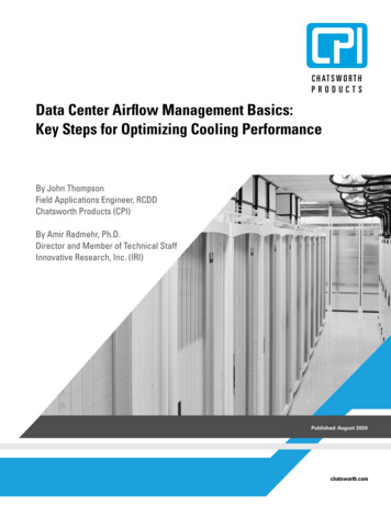
Chatsworth Products White Paper2IntroductionOne of the main operational challenges in data centers is optimizing cooling performance.Optimizing cooling performance improves capacity utilization and may allow cooling systemadjustments that reduce cooling costs and OPEX. In air-cooled data centers, the key is tounderstand how changes in the site impact cooling, and how airflow management can be usedas a tool for optimization.There are practical limits to how much power or air can be delivered to a cabinet depending oneach room design. However, today’s average cabinet density of 8-10 kW1 is well within the coolingcapacity of typical airflow supplied to the cabinet. With this in mind, it is likely many organizationsstill have some unused or possibly wasted cooling capacity in their air-cooled data center,especially if they do not practice a comprehensive airflow management strategy.This white paper, by Chatsworth Products (CPI) and Innovative Research Inc. (IRI), provides anoverview of the key steps for optimizing the cooling performance of air-cooled data centers. Thisincludes employing a Computational Fluid Dynamics (CFD) modeling software tool for analysis andexercising airflow management best practices that will help data center managers understand thewhat and how of optimizing airflow and, consequently, cooling performance.Note: The steps and solutions in this white paper address raised-floor data centers. Most ofthe steps and solutions also apply to non-raised-floor data centers.Data Center Airflow Management Basics White Paperchatsworth.com
Chatsworth Products White Paper3Key Steps for Optimizing Cooling PerformanceAirflow management is the principle method of optimizing cooling performance in air-cooleddata centers. Airflow management allows data centers to closely match the supply and demandof conditioned air. Not focusing on this relationship, will add unnecessary capacity, which justdrives cooling costs up.Optimizing cooling performance (in raised floor data centers) has five key steps:1. Identifying the causes of cooling issues2. Sealing openings3. Balancing airflow4. Adding containment to isolate hot and cold air5. Adjusting the cooling systemStep 1: Identifying Causes of Cooling IssuesThere are many factors that impact airflow in the data center white space, including: The shape and size of the room Raised floor and ceiling heights Locations, types, and settings of cooling units Location and open area of perforated tiles Location and open area of cutouts Location and size of under-floor obstructions Location, orientation, heat load, and airflow of cabinets Location and size of above-floor obstructionsComputational Fluid Dynamics (CFD) modeling software simulates all these factors to help datacenter managers visualize temperature distribution, airflow patterns, and pressure differentialsin computer rooms. With careful modeling, it is possible to quickly see where conditioned air iswasted and how airflow management methods, like sealing cable openings in raised floors andaisle containment, improve operating conditions and allow cost-saving adjustments to coolingequipment.Every site is unique, which makes CFD modeling software a crucial tool for identifying causes ofcooling issues. Use it to create a digital twin of your data center and to analyze the impacts ofchanges prior to deployment in order to maintain optimal conditions for the site.The goals and techniques of airflow management are universal: to deliver the correct amountand condition of air to the front of equipment in the cabinets. The techniques are to sealopenings that leak cooled air, to add/remove perforated tiles, and to isolate hot and cold air tohelp reduce the volume of cooled air required by the equipmentData Center Airflow Management Basics White Paperchatsworth.com
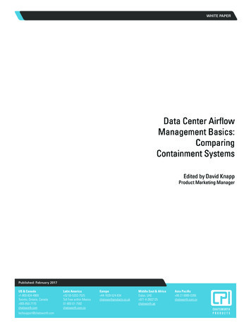
Chatsworth Products White Paper4CFD modeling illuminates a mismatch between airflow demand and supply, as equipment load typically varies across theroom (Figure 1).Room Layout2 kW RacksCable Openings6 kW RacksDemand Demand 2,500 CFM7,000 CFMSupply Supply 4,300 CFM4,300 CFM25% Open TilesHeat Load: 64 kWTotal Airflow Demand: 9,200 CFMTotal Airflow Supplied: 12,000 CFMSupply Temperature: 65 F (18.3 C)Figure 1: This is a typical symmetrical room layout, but note the difference in heat load between cabinets on the left and right side of the room. Theheat load difference translates into a difference in airflow demand, but the uniform room design will deliver the same amount of air to all racks.Image from TileFlow CFD modeling software by Innovative Research, Inc. tileflow.comData Center Airflow Management Basics White Paperchatsworth.com
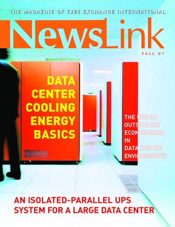
Chatsworth Products White Paper5Another factor that affects cooling efficiency in raised floor environments is unsealed openingsin raised floor tiles. Unsealed openings cause a significant amount of conditioned supply air tobe lost, resulting in wasted energy cost (Figure 2).Airflow From Perforated Tiles and Cable Openings2,500 CFM leaks throughcable openingsSame amount of airflow is supplied tothe low and high-densty racksFigure 2: The red plumes in the screenshot of the CFD model above show conditioned air leaking through unsealed cable openings at the back ofcabinets and, therefore, not contributing to cooling equipment directly.In this example, 2,500 CFM is lost through unsealed cable openings. Refer to Figure 1, and note that there is 9,200 CFM required, 12,000 CFM suppliedand 2,500 CFM leaking. That leaves only 300 CFM of extra supply (unused capacity).Image from TileFlow CFD modeling software by Innovative Research, Inc. tileflow.comData Center Airflow Management Basics White Paperchatsworth.com
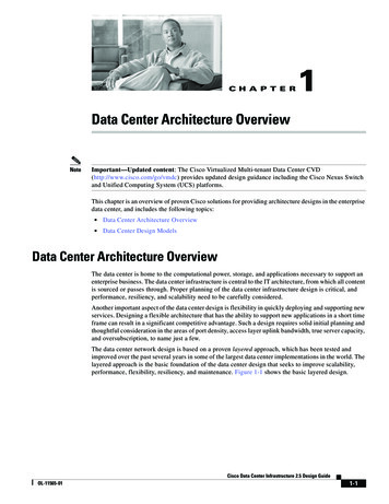
Chatsworth Products White Paper6The combination of mismatched airflow for high density cabinets and raised floor openings that are not properly sealed is uneventemperature in the room, wasted chilled air on one side of the room and an insufficient amount of chilled air on the other side of theroom. The result is recirculation of high temperature air on the other side of the room (Figure 3).Room Temperatures MapHot air penetrates into cold aisleWastage of cold airFigure 3: Result of poor airflow in a space that should have sufficient cooling. Blue shows an overcooled area. Red shows an undercooled area.Image from TileFlow CFD modeling software by Innovative Research, Inc. tileflow.comObviously, individuals would be able to feel the temperature variations in the room. But, in a large and complex data center, how woulddata center managers know the most effective steps to fix the problem? Is more cooling capacity necessary? Is moving equipmentneeded? Is airflow containment appropriate? If so, where?The good news is that it is possible to make changes in the CFD model and see the impact before taking action. The CFD model worksas a digital twin and is a fundamental planning and optimization tool.Data Center Airflow Management Basics White Paperchatsworth.com
Chatsworth Products White Paper7Step 2: Sealing OpeningsThe example site shown in Figures 1-3 above can be improved by controlling airflowwith airflow management accessories in the room and inside the cabinets. There isno need for additional cooling capacity or equipment.Start by modeling the effects of sealing openings in the raised floor (Figure 4). If theeffect is positive, then seal the openings with brush-sealed or gasketed grommets.These protective grommets cover openings in raised floor tiles and have a seal thatblocks most of the airflow through the opening. Individual cables, cable bundles,power cords or piping can then pass through the opening in the grommet withminimal leakage of conditioned air (Figure 5).Figure 5: Raised Floor Grommets areavailable in various sizes and shapes.They seal openings in raised floor tileswith brushes or rubberized gaskets toreduce air leaks around cables, conduitand piping. Use these grommets to sealopenings in raised floor tiles when theinterstitial space under the floor is usedas a supply air plenum.Airflow from Perforated Tiles and Cable OpeningsAirflow Leakage throughgrommets is minimal (280 CFM)More airflow is supplied to thehigh-density racksFigure 4: CFD modeling shows that sealing cable openings reduces wasted air from 2,500 CFM to 280 CFM. That provides an additional 2,220 CFMfor cooling equipment. Image from TileFlow CFD modeling software by Innovative Research, Inc. tileflow.comNext, create a top-to-bottom seal within each cabinet. Use filler panels to seal openrack-mount spaces in cabinets between rack-mount equipment. Use air dam kit toseal the space between the equipment mounting rails and the top, bottom and sidepanels of the cabinet. This creates a front-rear separation within the cabinet thatrequires conditioned air to pass though equipment and prevents heated air fromcirculating back to the front of the cabinet. (Figure 6).Data Center Airflow Management Basics White PaperFigure 6: Air Dam Kit andSnap-In Filler Panels create atop-to-bottom seal within thecabinet so that conditionedsupply air goes throughequipment and not around it.chatsworth.com
Chatsworth Products White Paper8Step 3: Balancing AirflowOnce floor and cabinet openings are sealed, the correct amount of airflow needs to be delivered to cabinets. Most data centersarrange cabinets around hot and cold aisles. First, it is important to ensure there are no vented floor tiles in the hot aisles. The airflowsupplied to the hot aisle does not directly cool racks. Vented floor tiles should only be placed in the cold aisles so that supply air isdelivered to the front of cabinets and equipment.The amount of air required will increase as cabinet power/heat load increases. So, it is beneficial to model the effects of varyingthe amount of perforation on floor tiles to determine the correct combination of floor tiles needed to deliver more air in front ofhigh-density cabinets (Figure 7).Modified Room Layout to Balance the AirflowGrommetsDemand Demand 2,500 CFM7,000 CFMSupply Supply 2,900 CFM8,200 CFM25% Open Tiles56% Open TilesHeat Load: 64 kWTotal Airflow Demand: 9,200 CFMTotal Airflow Supplied: 12,000 CFMSupply Temperature: 65 F (18.3 C)Figure 7: To balance airflow so that airflow supply more closely matches airflow demand, 25% open tiles are placed in front of 2 kW cabinets and56% open tiles are placed in front of 6 kW cabinets. Image from TileFlow CFD modeling software by Innovative Research, Inc. tileflow.comData Center Airflow Management Basics White Paperchatsworth.com
Chatsworth Products White Paper9Step 4: Adding Containment to Isolate Hot and Cold AirThe next step is to execute the CFD model of the room with the proposed enhancements to ensure sufficient airflow and acceptablerack inlet temperatures (Figure 8). Air cooled rack-mount equipment uses internal fans to draw air through the equipment chassis. If itis not possible to deliver enough cold air to the front of the cabinet, heated air will be pulled under, over and around to the front of thecabinets. The CFD model will show the extent of recirculation and the impact on temperature and airflow in the room.Room Temperatures MapRoom air penetrates into cold aislesFigure 8: CFD modeling shows good cabinet temperatures in the center of each aisle with some recirculation of hot air over and around cabinets.Image from TileFlow CFD modeling software by Innovative Research, Inc. tileflow.comData Center Airflow Management Basics White Paperchatsworth.com
Chatsworth Products White Paper10If inlet temperatures are still too high in the cold aisles, then the recommendation is to add containment to block hot airflow under,over and around cabinets. Each component should be modeled individually and in combinations to understand the impact to the datacenter. Most cabinets are placed on leveler feet when installed into the data center, so there is a gap between the floor and the baseof the cabinet. It is possible to block the airflow under cabinets using bottom panels. To block airflow over and around cabinets, aislecontainment doors (Figure 9) are the solution. If necessary, the entire aisle can be sealed with either a ceiling (Figure 10) to keep airin the aisle, or a duct (Figure 11) to exhaust air from the room. Alternately, cabinets with vertical exhaust ducts can be used instead ofaisle containment (Figure 12). To maximize performance, the containment method should provide a strong seal between componentsto minimize leakage.Figure 9: Aisle containment doors are available in various styles andwidths. Ensure a good seal between the door frame and the sides of theadjoining cabinets. Consider a door that includes a mechanism to returnand maintain it in a closed position.Figure 10: Cold Aisle Containment (CAC) typically uses a ceiling to coverthe contained aisle. Cold air is delivered to and isolated within thecontained aisle.Figure 11: Hot Aisle Containment (HAC) typically uses a duct to surroundthe contained aisle. Hot air is isolated within and exhausted from the roomthrough the duct.Figure 12: Cabinets with vertical exhaust ducts have a solid rear doorand top-mounted duct. Hot air is isolated and exhausted from the roomthrough the duct. These “chimney” cabinets are an alternative to aislecontainment.Data Center Airflow Management Basics White Paperchatsworth.com
Chatsworth Products White Paper11Step 5: Adjusting the Cooling SystemAdding containment with a good seal and maintaining strong airflow management discipline result in eliminating hot spots, moreuniform room and cabinet temperatures (Figure 13), and more reliable control when adjusting room conditions. Once the airflowand containment steps are in place, data center managers can model and then make small adjustments to room temperatureand airflow to optimize cooling conditions. As a rule of thumb, every 1-degree increase in supply temperature will reduce 2-4%energy consumption.Room and Racks TemperatureNo hot spots in the roomRack inlet temperatures are uniform and acceptableFigure 13: CFD modeling shows CAC with uniform temperature and no hot spots. Supply temperature can now be raised to lower cooling costs.HAC and cabinets with vertical exhaust ducts deliver similar results. The type of containment that is used depends on the architectural constraints ofthe space and amount of heat load variation in the racks.Image from TileFlow CFD modeling software by Innovative Research, Inc. tileflow.comData Center Airflow Management Basics White Paperchatsworth.com
Chatsworth Products White Paper12CFD modeling also shows the pressure differences between the room and contained spaces which will help managers, engineers,and technicians adjust airflow to minimize the pressure differences while maintaining correct airflow (Figure 14). Reduction in airflowallows them to reduce the number of air handling units or operate units with variable-speed fans at lower speeds, further reducingcooling cost.Room Pressure MapThe pressure in bothcold aisles is slightlypositive. This is thedesired outcome.Figure 14: CFD modeling shows CAC with slightly positive pressure in both cold aisles. This maintains cold-to-hot airflow direction and eliminatesleakage of hot air into the cold aisle, but allows adjustment of air handlers to minimal fan speeds.Conversely, HAC and cabinets with vertical exhaust ducts would have slightly negative pressure in the contained aisle or duct to maintaincold-to-hot airflow direction and eliminate leakage.Image from TileFlow CFD modeling software by Innovative Research, Inc. tileflow.comData Center Airflow Management Basics White Paperchatsworth.com
Chatsworth Products White Paper13ConclusionCFD modeling and airflow management are critical to operating a highly efficient data center and optimizing cooling performance.CFD modeling allows data center managers to create a digital twin of their facility and simulate effects of new equipment andchanges in airflow management and cooling system settings. Airflow management provides a toolkit of methods for controllingairflow and preventing the mix of supply and return air.The five key steps to optimizing cooling performancediscussed in this paper provide a simple guideline foroptimizing data center white spaces. For assistanceidentifying opportunities to optimize cooling performanceand possibly lower cooling costs, contact CPI’s FieldApplications Engineers today.Data Center Airflow Management Basics White Paperchatsworth.com
Chatsworth Products White Paper14Additional Information on ContainmentFor a deeper explanation of CFD modeling software and how customers are using it to plan and optimize site utilization,watch the on-demand webinar Improving Data Center Cooling Using Computational Fluid Dynamics, available ter/webinarsFor more details on the three basic types of containment systems, including a comparison of the architectural and design considerationsfor each system, read the companion paper, Data Center Airflow Management Basics: Comparing Containment Systems, available oduct-information/cpi-white-papersFor more details on how containment allows data center managers to reduce the volume of air delivered to coolequipment and raise room temperatures, resulting in several improved efficiencies and reduction in cooling energy costs,read the white paper, Data Center Airflow Management Basics: Economics of Containment Systems, available oduct-information/cpi-white-papersReferences1Rich Miller. Cabinet Density Keeps Rising at Enterprise Data Centers. April 27, eeps-rising-at-enterprise-data-centers/Original source cited: Informatech, AFCOM Data Center Institute, State of the Data Center Report, March 2020.Data Center Airflow Management Basics White Paperchatsworth.com
ContributorsJohn Thompson – Field Applications EngineerJohn Thompson has more than 30 years of technical experience in the telecommunicationsindustry and has been a BICSI-certified RCDD since 1997. As a contractor, John ownedand operated a structured cabling installation company in the Mid-Atlantic region. Beforejoining CPI, John was a consultant for a special systems design firm in Baltimore, MDthat teamed with architects, MEP firms and worked directly with end users. In addition toassisting with AutoCAD design, John not only developed new construction specificationdocuments, but served as a project manager for health care and higher education facilitiesprojects across the United States. Since joining Chatsworth more than 10 years ago, Johnhas assisted in the design of both new and existing data centers ranging in size from just afew cabinets to many hundreds of cabinets.Amir Radmehr – Director and Member of Technical StaffDr. Amir Radmehr has worked at IRI since 1997. He has over 28 years of experiencein developing and utilizing CFD software products. In the past twenty years, he hasbeen working on IRI’s CFD product “TileFlow”. He has used both measurements andcomputational modeling to identify and resolve cooling issues in data centers. He holds aPh.D. in Mechanical Engineering from the University of Minnesota. He has written morethan 30 research publications.While every effort has been made to ensure the accuracy of all information, CPI does not accept liability for any errors or omissionsand reserves the right to change information and descriptions of listed services and products. 2020 Chatsworth Products, Inc. All rights reserved. Chatsworth Products, Clik-Nut, CPI, CPI Passive Cooling, eConnect, Evolution,GlobalFrame, MegaFrame, Motive, QuadraRack, RMR, Saf-T-Grip, Secure Array, SeismicFrame, SlimFrame, TeraFrame and Velocityare federally registered trademarks of Chatsworth Products. CUBE-iT, EuroFrame and Simply Efficient are trademarks of ChatsworthProducts. All other trademarks belong to their respective companies.07/20 MKT-60020-741
Data Center Airflow Management Basics White Paper chatsworth.com Key Steps for Optimizing Cooling Performance Airflow management is the principle method of optimizing cooling performance in air-cooled data centers. Airflow management allows data centers t