Transcription
ConCh04v2.fm Page 217 Thursday, July 11, 2002 4:33 PMC H A P T E R 4Tuned MassDamperSystems4.1INTRODUCTIONA tuned mass damper (TMD) is a device consisting of a mass, a spring, and a damperthat is attached to a structure in order to reduce the dynamic response of thestructure. The frequency of the damper is tuned to a particular structural frequency sothat when that frequency is excited, the damper will resonate out of phase with thestructural motion. Energy is dissipated by the damper inertia force acting on thestructure. The TMD concept was first applied by Frahm in 1909 (Frahm, 1909) toreduce the rolling motion of ships as well as ship hull vibrations. A theory for theTMD was presented later in the paper by Ormondroyd and Den Hartog (1928),followed by a detailed discussion of optimal tuning and damping parameters in DenHartog’s book on mechanical vibrations (1940). The initial theory was applicable foran undamped SDOF system subjected to a sinusoidal force excitation. Extension ofthe theory to damped SDOF systems has been investigated by numerous researchers.Significant contributions were made by Randall et al. (1981), Warburton (1981, 1982),Warburton and Ayorinde (1980), and Tsai and Lin (1993).This chapter starts with an introductory example of a TMD design and a briefdescription of some of the implementations of tuned mass dampers in buildingstructures. A rigorous theory of tuned mass dampers for SDOF systems subjectedto harmonic force excitation and harmonic ground motion is discussed next. Various cases, including an undamped TMD attached to an undamped SDOF system, adamped TMD attached to an undamped SDOF system, and a damped TMDattached to a damped SDOF system, are considered. Time history responses for a217
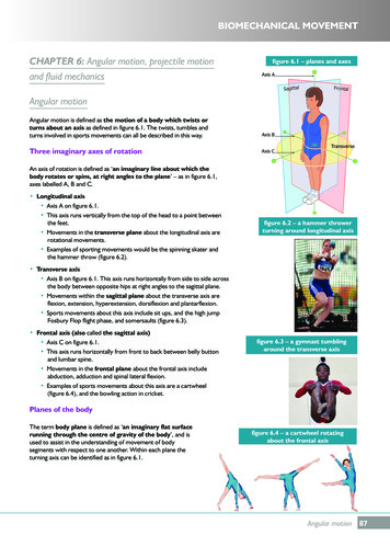
ConCh04v2.fm Page 218 Thursday, July 11, 2002 4:33 PM218Chapter 4Tuned Mass Damper Systemsrange of SDOF systems connected to optimally tuned TMD and subjected to harmonic and seismic excitations are presented. The theory is then extended to MDOFsystems, where the TMD is used to dampen out the vibrations of a specific mode.An assessment of the optimal placement locations of TMDs in building structures isincluded. Numerous examples are provided to illustrate the level of control that canbe achieved with such passive devices for both harmonic and seismic excitations.4.2AN INTRODUCTORY EXAMPLEIn this section, the concept of the tuned mass damper is illustrated using the twomass system shown in Figure 4.1. Here, the subscript d refers to the tuned massdamper; the structure is idealized as a single degree of freedom system. Introducingthe following notationk2ω ----m(4.1)c 2ξωm(4.2)k2ω d ------dmd(4.3)c d 2ξ d ω d m d(4.4)and defining m as the mass ratio,mm ------dm(4.5)the governing equations of motion are given byp2·····Primary mass ( 1 m )u 2ξωu ω u ----- – mu dm(4.6)pkdkmdmccduFIGURE 4.1: SDOF-TMD system.u 1 ud
ConCh04v2.fm Page 219 Thursday, July 11, 2002 4:33 PMSection 4.2An Introductory Example2·····Tuned mass u d 2ξ d ω d u d ω d u d – u219(4.7)The purpose of adding the mass damper is to limit the motion of the structurewhen it is subjected to a particular excitation. The design of the mass damperinvolves specifying the mass md , stiffness kd , and damping coefficient cd . Theoptimal choice of these quantities is discussed in Section 4.4. In this example, thenear-optimal approximation for the frequency of the damper,ωd ω(4.8)is used to illustrate the design procedure. The stiffnesses for this frequency combination are related byk d mk(4.9)Equation (4.8) corresponds to tuning the damper to the fundamental period of thestructure.Considering a periodic excitation,p p̂ sin Ωt(4.10)the response is given byu û sin ( Ωt δ 1 )u d û d sin ( Ωt δ 1 δ 2 )(4.11)(4.12)where û and δ denote the displacement amplitude and phase shift, respectively.The critical loading scenario is the resonant condition, Ω ω. The solution for thiscase has the following form:p̂1û -------- --------------------------------------21km 1 2ξ- -------- ----2ξmd(4.13)1û d --------û2ξ d(4.14)2ξ1tan δ 1 – ------ -------m 2ξ d(4.15)πtan δ 2 – --2(4.16)
ConCh04v2.fm Page 220 Thursday, July 11, 2002 4:33 PM220Chapter 4Tuned Mass Damper SystemsNote that the response of the tuned mass is 90º out of phase with the response of theprimary mass. This difference in phase produces the energy dissipation contributedby the damper inertia force.The response for no damper is given byp̂ 1û --- ------ k 2ξ (4.17)πδ 1 – --- 2 (4.18)To compare these two cases, we express Eq. (4.13) in terms of an equivalentdamping ratio:p̂ 1û --- -------- k 2ξ e (4.19)m2ξ1 2ξ e ----- 1 ------ -------- m 2ξ d 2(4.20)whereEquation (4.20) shows the relative contribution of the damper parameters to thetotal damping. Increasing the mass ratio magnifies the damping. However, since theadded mass also increases, there is a practical limit on m. Decreasing the dampingcoefficient for the damper also increases the damping. Noting Eq. (4.14), the relative displacement also increases in this case, and just as for the mass, there is a practical limit on the relative motion of the damper. Selecting the final design requires acompromise between these two constraints.Example 4.1: Preliminary design of a TMD for a SDOF systemSuppose ξ 0 and we want to add a tuned mass damper such that the equivalentdamping ratio is 10%. Using Eq. (4.20), and setting ξ e 0.1 , the following relationbetween m and ξ d is obtained:m2ξ1 2----- 1 ------ -------- 0.1 m 2ξ d 2(1)The relative displacement constraint is given by Eq. (4.14):1û d -------- û 2ξ d (2)
ConCh04v2.fm Page 221 Thursday, July 11, 2002 4:33 PMSection 4.2An Introductory Example221Combining Eq. (1) and Eq. (2) and setting ξ 0 leads to2û dm----- 1 ----- 0.1 û 2(3)Usually, û d is taken to be an order of magnitude greater than û . In this case, Eq. (3)can be approximated asm û d ----- ----- 0.12 û (4)The generalized form of Eq. (4) follows from Eq. (4.20):1m 2ξ e ------------- û d û (5)Finally, taking û d 10û yields an estimate for m:2 ( 0.1 )m --------------- 0.0210(6)This magnitude is typical for m. The other parameters are1 û ξ d --- ----- 0.052 û d (7)k d mk 0.02k(8)and from Eq. (4.9)It is important to note that with the addition of only 2% of the primary mass,we obtain an effective damping ratio of 10%. The negative aspect is the large relative motion of the damper mass; in this case, 10 times the displacement of the primary mass. How to accommodate this motion in an actual structure is an importantdesign consideration.A description of some applications of tuned mass dampers to building structures is presented in the following section to provide additional background on thistype of device prior to entering into a detailed discussion of the underlying theory.
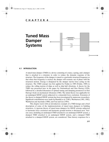
ConCh04v2.fm Page 222 Thursday, July 11, 2002 4:33 PM2224.3Chapter 4Tuned Mass Damper SystemsEXAMPLES OF EXISTING TUNED MASS DAMPER SYSTEMSAlthough the majority of applications have been for mechanical systems, tunedmass dampers have been used to improve the response of building structures underwind excitation. A short description of the various types of dampers and severalbuilding structures that contain tuned mass dampers follows.4.3.1 Translational Tuned Mass DampersFigure 4.2 illustrates the typical configuration of a unidirectional translationaltuned mass damper. The mass rests on bearings that function as rollers and allowthe mass to translate laterally relative to the floor. Springs and dampers are insertedbetween the mass and the adjacent vertical support members, which transmit thelateral “out-of-phase” force to the floor level and then into the structural frame.Bidirectional translational dampers are configured with springs/dampers in twoorthogonal directions and provide the capability for controlling structural motion intwo orthogonal planes. Some examples of early versions of this type of damper aredescribed next. John Hancock Tower (Engineering News Record, Oct. 1975)Two dampers were added to the 60-story John Hancock Tower in Boston to reducethe response to wind gust loading. The dampers are placed at opposite ends of thefifty-eighth story, 67 m apart, and move to counteract sway as well as twisting due tothe shape of the building. Each damper weighs 2700 kN and consists of a lead-filledsteel box about 5.2 m square and 1 m deep that rides on a 9-m-long steel plate. Thelead-filled weight, laterally restrained by stiff springs anchored to the interior columns of the building and controlled by servo-hydraulic cylinders, slides back andforth on a hydrostatic bearing consisting of a thin layer of oil forced through holesin the steel plate. Whenever the horizontal acceleration exceeds 0.003g for two consecutive cycles, the system is automatically activated. This system was designed andmanufactured by LeMessurier Associates/SCI in association with MTS SystemCorp., at a cost of around 3 million dollars, and is expected to reduce the sway ofthe building by 40 to 50%.SupportmdFloor beamDirection of motionFIGURE 4.2:Schematic diagram of a translational tuned mass damper.
ConCh04v2.fm Page 223 Thursday, July 11, 2002 4:33 PMSection 4.3Examples of Existing Tuned Mass Damper Systems 223 Citicorp Center (Engineering News Record, Aug. 1975, McNamara 1977,Petersen 1980)The Citicorp (Manhattan) TMD was also designed and manufactured by LeMessurier Associates/SCI in association with MTS System Corp. This building is 279 mhigh and has a fundamental period of around 6.5 s with an inherent damping ratioof 1% along each axis. The Citicorp TMD, located on the sixty-third floor in thecrown of the structure, has a mass of 366 Mg, about 2% of the effective modal massof the first mode, and was 250 times larger than any existing tuned mass damper atthe time of installation. Designed to be biaxially resonant on the building structurewith a variable operating period of 6.25 s 20%, adjustable linear damping from 8to 14%, and a peak relative displacement of 1.4 m, the damper is expected toreduce the building sway amplitude by about 50%. This reduction corresponds toincreasing the basic structural damping by 4%. The concrete mass block is about2.6 m high with a plan cross section of 9.1 m by 9.1 m and is supported on a series oftwelve 60-cm-diameter hydraulic pressure-balanced bearings. During operation, thebearings are supplied oil from a separate hydraulic pump, which is capable of raising the mass block about 2 cm to its operating position in about 3 minutes. Thedamper system is activated automatically whenever the horizontal accelerationexceeds 0.003g for two consecutive cycles and will automatically shut itself downwhen the building acceleration does not exceed 0.00075g in either axis over a30-minute interval. LeMessurier estimates Citicorp’s TMD, which cost about 1.5million dollars, saved 3.5 to 4 million dollars. This sum represents the cost of some2800 tons of structural steel that would have been required to satisfy the deflectionconstraints. Canadian National Tower (Engineering News Record, 1976)The 102-m steel antenna mast on top of the Canadian National Tower in Toronto(553 m high including the antenna) required two lead dampers to prevent theantenna from deflecting excessively when subjected to wind excitation. The dampersystem consists of two doughnut-shaped steel rings, 35 cm wide, 30 cm deep, and2.4 m and 3 m in diameter, located at elevations 488 m and 503 m. Each ring holdsabout 9 metric tons of lead and is supported by three steel beams attached to thesides of the antenna mast. Four bearing universal joints that pivot in all directionsconnect the rings to the beams. In addition, four separate hydraulically activatedfluid dampers mounted on the side of the mast and attached to the center of eachuniversal joint dissipate energy. As the lead-weighted rings move back and forth,the hydraulic damper system dissipates the input energy and reduces the tower’sresponse. The damper system was designed by Nicolet, Carrier, Dressel, and Associates, Ltd., in collaboration with Vibron Acoustics, Ltd. The dampers are tuned tothe second and fourth modes of vibration in order to minimize antenna bendingloads; the first and third modes have the same characteristics as the prestressed concrete structure supporting the antenna and did not require additional damping. Chiba Port Tower (Kitamura et al., 1988)
ConCh04v2.fm Page 224 Thursday, July 11, 2002 4:33 PM224Chapter 4Tuned Mass Damper SystemsChiba Port Tower (completed in 1986) was the first tower in Japan to be equippedwith a TMD. Chiba Port Tower is a steel structure 125 m high weighing 1950 metrictons and having a rhombus-shaped plan with a side length of 15 m. The first andsecond mode periods are 2.25 s and 0.51 s, respectively for the x direction and 2.7 sand 0.57 s for the y direction. Damping for the fundamental mode is estimated at0.5%. Damping ratios proportional to frequencies were assumed for the highermodes in the analysis. The purpose of the TMD is to increase damping of the firstmode for both the x and y directions. Figure 4.3 shows the damper system. Manufactured by Mitsubishi Steel Manufacturing Co., Ltd., the damper has mass ratioswith respect to the modal mass of the first mode of about 1/120 in the x directionand 1/80 in the y direction; periods in the x and y directions of 2.24 s and 2.72 s,respectively; and a damper damping ratio of 15%. The maximum relative displacement of the damper with respect to the tower is about 1 m in each direction.Reductions of around 30 to 40% in the displacement of the top floor and 30% inthe peak bending moments are expected.The early versions of TMDs employ complex mechanisms for the bearing anddamping elements, have relatively large masses, occupy considerable space, and arequite expensive. Recent versio
Each damper weighs 2700 kN and consists of a lead-filled steel box about 5.2 m square and 1 m deep that rides on a 9-m-long steel plate. The lead-filled weight, laterally restrained by stiff springs anchored to the interior col-umns of the building and controlled by servo-hydraulic cylinders, slides back and forth on a hydrostatic bearing consisting of a thin layer of oil forced through holes .