Transcription
Universal Devices Administrative ConsoleUser GuideForUniversal Devices’ Administrative Console(ISY)-1-
Universal Devices Administrative ConsoleTable of Contents1.PURPOSE62.THEORY OF uisites4.1.1Host Computer Software4.1.2Network8884.2Host Computer Configuration4.2.1UPnP Configuration4.2.2Java Installation8895.5.1USING THE BROWSER BASED ADMINISTRATIVE CONSOLEInitial Setup10105.2Administrative Console’s Components5.2.1Navigation Pane Components5.2.1.1Root Node5.2.1.2System Configuration Node5.2.1.3Schedules Node5.2.1.4Alarms Node5.2.1.5Physical Device (ISY) node5.2.1.6Attached Device Node (Thermostat Node)5.2.1.7Attached Device Configuration Node5.2.1.8Group Node5.2.2Overview View5.2.3System Configuration View5.2.3.1Synchronizing with Computer’s Time5.2.3.2Manually Adjusting the Date and Time5.2.3.3Synchronizing with Internet Time5.2.3.4Configuring the Notifications Engine5.2.4Schedules View5.2.4.1Adding a Schedule for a Specific Time5.2.4.2Adding a Schedule for Everyday at a Given Time5.2.4.3Adding a Repeated Schedule for Everyday5.2.4.4Adding a Schedule for Certain Days of the Week5.2.4.5Adding a Repeated Schedule for Certain Days of the Week5.2.4.6Holding Schedules on a Certain Date5.2.4.7Holding Schedules within a Duration5.2.4.8Removing a Schedule5.2.4.9Removing All Schedules5.2.4.10Changing a Schedule5.2.5Alarms View5.2.5.1Setting an Alarm5.2.5.2Resetting 26272728293031323233343434
Universal Devices Administrative Console5.2.65.2.75.2.85.2.9Physical (ISY) Device ViewAttached Device ViewAttached Device Configuration ViewGroup View353536366.LOGICAL GROUPING376.1Creating a Logical Group386.2Moving a Node396.3Removing a Node from a Group397.TRENDING407.1Viewing the History/Trend7.1.1 Viewing by Group7.1.2 Zooming In & Out7.1.3 Printing the Chart7.1.4 Saving the Chart7.1.5 Viewing the Log4043444445467.247Resetting the History/Trend8.UPGRADING THE FIRMWARE478.1Manually Upgrading the Firmware478.2Automatically Upgrading the Firmware48-3-
Universal Devices Administrative ConsoleTable of FiguresFigure 1 – UPnP Configuration. 9Figure 2 – Setting the User-id and Password . 11Figure 3 – Navigation and View Panes. 11Figure 4 – Root Node Menu. 13Figure 5 – Schedules Node Menu . 14Figure 6 – Alarms Node Menu. 15Figure 7 – Physical Device (ISY) Node Menu . 16Figure 8 – Attached Device Node Menu. 17Figure 9 – Attached Device Configuration Node Menu . 18Figure 10 – Group Node Menu . 19Figure 11 – Overview. 20Figure 12 – System Configuration View . 21Figure 13 – Adjusting the Date and Time . 22Figure 14 – Configuring the Notifications Engine. 23Figure 15 – Modifying the Notifications Settings. 24Figure 16 – Schedules View . 25Figure 17 – Adding a Schedule for a Specific Time . 26Figure 18 – Adding a Schedule for Everyday at a Given Time . 27Figure 19 – Adding a Repeated Schedule for Everyday . 27Figure 20 – Adding a Schedule for Certain Days of the Week. 28Figure 21 – Adding a Repeated Schedule for Certain Days of the Week . 29Figure 22 – Holding Schedules on a Certain Date . 30Figure 23 – Holding Schedules within a Duration. 31Figure 24 – Removing a Schedule . 32Figure 25 – Removing All Schedules . 32Figure 26 – Changing a Schedule . 33Figure 27 – Alarms View . 34Figure 28 – Resetting Notifications . 34Figure 29 – Attached Device View . 35Figure 30 – Attached Device Configuration View. 36Figure 31 – Creating a Logical Group . 38Figure 32 – Renaming a Group . 38Figure 33 – Dragging and Dropping Nodes into a Group. 39Figure 34 – Removing a node from a Group . 39Figure 35 – Viewing the History/Trend . 40Figure 36 – Trending Dialog. 41Figure 37 – Trending Tool Tips . 42Figure 38 - Viewing by Group . 43Figure 39 – Printing the Chart. 44Figure 40 – Saving the Chart. 45Figure 41 – Viewing the Log in Excel . 46Figure 42 – Resetting the History/Trend. 47Figure 43 - Manually Upgrading the Firmware . 47Figure 44 – Automatic Notification of New/Updated Firmware . 48-4-
Universal Devices Administrative ConsoleFigure 45 – Automatically Upgrading the Firmware . 48-5-
Universal Devices Administrative Console1.PurposeThe purpose of this document is to guide the system’s installer with the stepsnecessary to operate Universal Devicess’ Network Controller.2.Theory of OperationAll Universal Devicess’ Network Controllers – herein after referred to as ISY –are empowered with UPnP (Universal Plug & Play) stack through utilization ofwhich all the devices on the network can seamlessly communicate with each otherand other computers on the network. ISY comes embedded with its own browserbased Administrative Console and, as such, there is no need for any softwareinstallation besides the normal Java runtime and, optionally, Excel to look at thelog files in a tabular form.UPnP enables the devices on the network to automatically show up as resourceson the “Network Neighborhood” or “My Network Places” on host computers justlike a shared printer. For UPnP to work, the devices need to be able to advertisetheir presence on the network and, furthermore, be able to communicate their statechanges to the host computers. In this respect, then, the main prerequisite forsuccessful operations is a network enabled environment.-6-
Universal Devices Administrative Console3.InstallationThis section left intentionally blank-7-
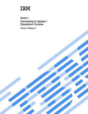
Universal Devices Administrative Console4.Configuration4.1 Prerequisites4.1.1 Host Computer Softwarei.ii.iii.iv.Windows XP (for other versions of Windows, a separate guide isprovided)Internet Explorer 6 and aboveJava 1.5 (JRE 1.5) – included in the setup diskMicrosoft Excel, for viewing logs4.1.2 Networki.ii.DHCP or Static IP enabled networkEthernet topology4.2 Host Computer ConfigurationConfiguration is comprised of two very easy steps:i.UPnP Configurationii.Java Installation4.2.1 UPnP ConfigurationUPnP is normally disabled on all computers by default. In order to make sureand/or to configure UPnP, please follow the following steps (refer to Figure 4-1):i.Click on My Network Places (either on the Start Menu or Desktop)ii.On the left Navigation Panea. If you see “Hide icons for networked UPnP devices”, you are done.No further action is necessaryb. If you see “Show icons for networked UPnP devices”, click on itand let the system get configured. You are done.-8-
Universal Devices Administrative ConsoleFigure 1 – UPnP Configuration4.2.2 Java InstallationIf you already have JRE 1.5v.6 installed, then no further action is necessary.Otherwise, click on the jre-1 5 0 06-windows-i586-p.exe on the installation CDto install JRE.-9-
Universal Devices Administrative Console5.Using the Browser based Administrative ConsoleThis section details the functionalities and the operations of the ISY browserbased Administrative Console.In order to use the Administrative Console, you would have to know the device’sURL. This said, however, since ISY is UPnP enabled, as soon as you plug in theISY to the network and power, it shows up in the “My Network Places” on all thecomputers on the network. As such, all you have to do is to click on the icon ofthe device appearing in the “My Network Places” (refer to Figure 1)Newly installed devices appear with names equal to their MAC-ADDRESS sothat they could be easily identified per installation. These names can easily bechanged to more meaningful names.5.1Initial SetupWhen you start up the Administrative Console for the first time, and if yourspecific ISY device is security aware, you will be presented with a userid/password dialog box.Please enter admin for both the user-id as well as the password. On the mainscreen (refer to Figure 2):i.Right mouse click on the Network icon on the left navigation paneii.Click on the Set Userid/Password menu itemEnter the desired userid and password and keep it in a safe place.Note: Login credentials may only be reset through Telnet or HyperTerminalsessions. Please consult the Installation and Configurations Guide.- 10 -
Universal Devices Administrative ConsoleFigure 2 – Setting the User-id and Password5.2Administrative Console’s ComponentsThe ISY’s Administrative Console is very intuitive and is essentially comprisedof two complementary panes (refer to Figure 3)i.The Navigation Pane is on the leftii.The View Pane is on the RightFigure 3 – Navigation and View PanesClicking on the icons on the Navigation Pane brings up the associated View in theView Pane.Right Mouse clicking on the icons on the Navigation Pane brings up a menu ofactions appropriate only for that node on the tree.- 11 -
Universal Devices Administrative Console5.2.1 Navigation Pane ComponentsThe Navigation Pane is a tree view at the top most of which is the wholeNetwork.The Navigation Pane may expand, grow, and shrink based upon the number ofother devices (i.e. thermostats) attached to an ISY as well as user actions. Thereare only 8 distinct types of nodes that you may find on the Navigation Pane (referto Figure 3):5.2.1.1Root NodeThis is the top most icon in the Navigation Pane which, at least initially, islabeled Network. Clicking on the node brings up the Overview Viewwhich encapsulates all the pertinent information for all the devices on thenetwork.Right mouse clicking on the Root Node brings up the menu for operationsthat will be applied globally to all the ISYs in the network and all thedevices attached to those ISYs (refer to Figure 4):i. Query All – allows the user to query all the settings for all theISYs and all the attached devices theretoii. Rename – allows the user to rename the Root Node to a moremeaningful nameiii. New Group – allows the user to create a new logical group. Pleaserefer to the Logical Grouping section 6iv. Logon – allows the user to log back into the whole network. Thisoperation is useful when an ISY, for one reason or another, hasbeen removed from the network or deactivatedv. Set Userid/Password - allows the user to set the Userid andPassword for all the ISYs on the networkvi. History/Trend – allows the user to get the history of all the settingon the network. Please refer to Trending section 7vii. Reset History/Trend – allows the user to reset the accumulatedhistoryviii. User Guide – brings up the user guide (this manual). Note: youneed Adobe Acrobat Reader to view the user guide.ix. Save Configuration – allows the user to save the entire currentsystem configuration with all the schedules, groups, and alarms.This saved configuration can then be used by Load Configurationmenu item (see x.) to update the system configuration based on thesaved statex. Load Configuration – allows the user to load a previously savedsystem configuration (see ix.). Upon loading, the system shallreboot for the updates to take effect.- 12 -
Universal Devices Administrative ConsoleFigure 4 – Root Node Menu5.2.1.2System Configuration NodeClicking on the System Configuration Node brings up the SystemConfiguration View. Please refer to System Configuration View section.There are no menus for this node.- 13 -
Universal Devices Administrative Console5.2.1.3Schedules NodeClicking on the Schedules Node brings up the Schedules View throughwhich the user may enter quite a sophisticated set of scheduling events.Please refer to the Schedules View section.For maximum flexibility, the Schedules Node can appear in three places:1) As a Global node right under the Root Node, in which case there isno menu defined and the schedules are defined globally (for all thedevices on the network).2) As a Group node right under any group3) As an individual schedule under an Attached Device Node forwhich the following menu has been defined (refer to Figure 5):The following menu has been defined for both the individual as well as thegroup alarms (refer to Figure 5):i.ii.iii.Copy – copies all the schedules, presented on the associatedSchedules View, into the clipboardCopy to All – copies all the schedules, presented on the associatedSchedules View, into all the other nodes (such as thermostats)under the same Physical Device Node or Group Node. Note: thismenu item is not enabled for Group schedules.Paste – pastes the contents of the clipboard (schedules) toAttached Device pointed to by the mouseFigure 5 – Schedules Node Menu- 14 -
Universal Devices Administrative Console5.2.1.4Alarms NodeClicking on the Alarms Node brings up the Alarms View through whichthe user may enter a sophisticated set of alarms/notification events. Pleaserefer to the Alarms View sectionFor maximum flexibility, the Alarms Node can appear in three places:1) As a Global node right under the Root Node, in which case there isno menu defined and the schedules are defined globally (for all thedevices on the network).2) As a Group node right under any group3) As an individual schedule under an Attached Device Node.The following menu has been defined for both the individual as well as thegroup alarms (refer to Figure 6):i.ii.iii.Copy – copies all the alarms definitions, presented on theassociated Alarms View, into the clipboardCopy to All – copies all the alarms, presented on the associatedAlarms View, into all the other nodes (such as thermostats) underthe same Physical Device Node or Group Node. The exceptionsare those alarms that have been defined at a global scope. Note:this menu item is not enabled for Group alarms.Paste – pastes the contents of the clipboard (alarms) to AttachedDevice pointed to by the mouseFigure 6 – Alarms Node Menu- 15 -
Universal Devices Administrative Console5.2.1.5Physical Device (ISY) nodeThis node identifies the ISY which is on the network. Note that each ISYmay have up to 32 other devices attached to it, in which case, there will bethat number of Attached Device Nodes right under the ISY node (see thenext item below).Clicking on Physical Device (ISY) Node brings up the Overview Viewonly for that ISY.The following menu is defined for Physical (refer to Figure 7)i.Query All – allows the user to query all the settings for allthe Attached Devices to this specific Physical Device (ISY)ii.Rename – allows the user to rename this specific ISY to amore meaningful nameiii.Add Node – allows the user to manually add a newAttached Device Node (such as thermostat or light)iv.Discover – instructs the ISY to scan for all the AttachedDevices and automatically add them to the hierarchy.v.Manual Upgrade – allows the user to manually upgradethe firmware using a file in the local file system.vi.Automatic Upgrade to n.n – is only available if the ISYfinds that there’s an update available. By clicking this menuitem, the firmware will automatically be upgraded to thelatest version without any other user intervention. Pleasenote that the user shall be notified of any new programupdates and will require a userid and password for the autoupdate site.Figure 7 – Physical Device (ISY) Node Menu- 16 -
Universal Devices Administrative Console5.2.1.6Attached Device Node (Thermostat Node)This node is mapped to any thermostat which is attached to a ISY.Clicking on this node brings up the Attached Device View.For maximum flexibility, this type of node can either be under a PhysicalDevice Node or a Group Node (please refer to the Logical Groupingsection for further information). Also, as children, this node has aSchedules Node as well as an Alarms node through the interactions withwhich schedules and alarms may be set at the individual device (such asthermostat) levels.For this node, the following menu has been define (refer to Figure 8)i.ii.iii.iv.v.vi.vii.Query All – allows the user to query all the settings for thisspecific node (such as thermostat)Rename – allows the user to rename this specific node(such as thermostat) to a more meaningful nameRemove Node – allows the user to manually remove thisnode from the ISYCopy – copies all the settings, presented on the associatedAttached Device View, into the clipboardCopy to All – copies all the settings, presented on theassociated Attached Device View, into all the other nodes(such as thermostats) under the same Physical Device Nodeor Group NodePaste – pastes the contents of the clipboard to AttachedDevice pointed to by the mouseFigure 8 – Attached Device Node Menu- 17 -
Universal Devices Administrative Console5.2.1.7Attached Device Configuration NodeClicking on this node brings up the Attached Device Configuration Viewon which the configuration parameters for an attached device (such asthermostat) can be set.This node is only present under an Attached Device Node.The following menu has been defined for this node (refer to Figure 9):i.Copy – copies all the settings, presented on the associatedAttached Device Configuration View, into the clipboardii.Copy to All – copies all the settings, presented on the associatedAttached Device Configuration View, into all the other thermostatsunder the same Physical Device Node or Group Nodeiii.Paste – pastes the contents of the clipboard to Attached Devicepointed to by the mouseFigure 9 – Attached Device Configuration Node Menu- 18 -
Universal Devices Administrative Console5.2.1.8Group NodeThermostats (Attached Physical Devices) can be logically grouped to forma meaningful category through drag and drop operations onto a GroupNode. In this case, then, the attached devices do not need to be constrainedby the physical connections imposed upon them. For further informationplease refer to Logical Grouping section.Clicking on this node – just like the Root Node and Physical Device Node– brings up the Overview View which shows a tabulated view of all thepertinent settings for all the devices (such as thermostats) under thatgroup.The following menu has been defined for this node (refer to Figure 10):i.ii.iii.Query All – allows the user to query all the settings for all theAttached Devices (such as thermostats) under this group.Rename – allows the user to rename this group to a moremeaningful nameRemove Group – allows the user to manually remove thisgroup from the Navigation Pane. All Attached Device Nodeswould automatically move back to their originating PhysicalDevice Node.Figure 10 – Group Node Menu- 19 -
Universal Devices Administrative Console5.2.2 Overview ViewOverview view is the tabulation of all the pertinent and important information inone place. It’s specifically designed to give the administrators an immediateaccess to most needed information while providing simple navigation featuresenable the user to jump to a node (i.e. thermostat) to perform necessary actions.As described in section 5.2.1, Overview view is displayed when any of thefollowing nodes are selected:i.Root Node – in this view, all the nodes (i.e. thermostats) in thenetwork are captured regardless of their physical attachment to anyISY.ii.Physical Device (ISY) Node – in this view, only those nodes thatare attached to the selected ISY are presented.iii.Group Node – in this view, only those nodes that are attached tothe selected Group Node are presented.Overview view provides a very useful and intuitive navigation (refer to Figure 11)mechanism: when a specific row in the table is clicked:i. The thermostat (Attached Device Node) is selected in theNavigation Paneii. The view is changed to Attached Device View where the user canimmediately change the settings for that node.Figure 11 – OverviewClicking on the table heading allows you to sort based on the values for thecolumn.- 20 -
Universal Devices Administrative Console5.2.3System Configuration ViewSystem Configuration View allows the users to manage global setting such asdate/time and notification settings. This view is divided into two sections (refer toFigure 12)i.Date/Time configuration which is on the topii.Notifications configuration which is at the bottomFigure 12 – System Configuration View5.2.3.1Synchronizing with Computer’s TimeClicking on this Synchronize with Computer’s Time button,automatically adjusts the date/time of all the ISYs on the network to thatof the attached computer.5.2.3.2Manually Adjusting the Date and TimeYou can adjust the date and time manually by following these steps (referto Figure 13)i.Click on the Manually Adjust button; you will be presentedwith the Adjust Date/Time dialogii.Choose the Daylight Saving Mode (top)iii.Enter the timeiv.Choose the time zonev.Choose the monthvi.Choose the day (you can click on the day buttons)vii.Choose the yearviii. Click Ok- 21 -
Universal Devices Administrative ConsoleFigure 13 – Adjusting the Date and Time5.2.3.3Synchronizing with Internet TimeIf the ISY has access to the internet and if you would like to takeadvantage of Network Time Servers – to maintain the most accurate timethen (refer to Figure 12) click on Synchronize with Internet Timebutton. A side effect of clicking this button is that each ISY, on thenetwork, will automatically update its time on a predefined interval andbased on Time Servers which are allocated dynamically (based on theirminimum supported query intervals).- 22 -
Universal Devices Administrative Console5.2.3.4Configuring the Notifications EngineBefore any alarms can be sent out, the Notifications Engine must beconfigured.To configure the Notifications Engine (Figure 14):i.ii.iii.iv.v.vi.Choose a messaging service provider from the MessagingProviders list.Enter the recipient’s information based on the specificinstructions given on the screen (Figure 14)Click on the Add buttonRepeat for all the recipientsEnter the interval/duration for Notifications to be sent (refer toFigure 15)Click on ApplyNote: Clicking on Restore Defaults button, removes all the recipients anddisables the Notification Engine.Figure 14 – Configuring the Notifications Engine- 23 -
Universal Devices Administrative ConsoleAt any moment in time, you can modify the list of recipients (refer toFigure 15) To edit the information for a recipient, click on the recipient’sname and then click on the Edit button To remove a recipient, click on the recipient’s name and thenclick on the Remove button To remove all recipients, click on the Remove All button.Figure 15 – Modifying the Notifications Settings- 24 -
Universal Devices Administrative Console5.2.4 Schedules ViewISY provides one of the most complete scheduling capabilities in the marketwhile keeping scheduling related administrative functions to the minimum. Therich user interface enables the user to create complex schedules in a matter ofseconds. As described before, Schedules View (refer to Figure 16) is activatedeither globally or per node (i.e. thermostat). At the node level, schedules mayeasily be copied and pasted to all other nodes within the same parent (i.e. RootNode, ISY Node, or Group Node).Schedules are presented in a familiar and easy to read tabular format the firstcolumn of which is always the English description of the schedule and the lastfour columns of which are always:ii.Active – if this schedule is active or it can be simply removediii.On Hold – if this schedule has been put on hold by a Hold schedule(refer to sections 5.2.4.6 & 5.2.4.7)iv.Last Fired – shows the date and time when this schedule was last runv.Global – identifies whether or not a is schedule at a global level (inwhich case, it cannot be overridden at the node levels)Note: The last 4 columns are not editableFigure 16 – Schedules ViewTo add a schedule, simply click on the Add button at the bottom of the SchedulesView (refer to Figure 16). This action will bring up the Schedule ConfigurationUtility through the usage of which you can add different types of schedules asoutline in the following subsections.Note: You can add all the desired schedules before submitting it to the ISY forexecution. When you are done with creating all the desired schedules, click on theApply button at the bottom of the Schedules View.- 25 -
Universal Devices Administrative Console5.2.4.1Adding a Schedule for a Specific TimeThis type of schedule is run only Once at a specific date and time (refer toFigure 17). In order to create this type of schedule, on the SchedulerConfiguration Utility:i.ii.iii.iv.Click on the Once (at the top)Choose the desired timeChoose the desired dateClick on OkFigure 17 – Adding a Schedule for a Specific Time- 26 -
Universal Devices Administrative Console5.2.4.2Adding a Schedule for Everyday at a Given TimeThis type of schedule is run Everyday at a specific time (refer to Figure18). In order to create this type of schedule, on the SchedulerConfiguration Utility:i.ii.iii.iv.Click on the Everyday (at the top)Click on the Once (in the middle)Choose the desired timeClick on OkFigure 18 – Adding a Schedule for Everyday at a Given Time5.2.4.3Adding a Repeated Schedule for EverydayThis type of schedule is run Everyday at a specific time (refer to Figure19) and repeated at the desired interval within the desired duration (lessthan 24 hours). In order to create this type of schedule, on the SchedulerConfiguration Utility:i.ii.iii.iv.v.vi.Click on the Everyday (at the top)Click on the Duration (in the middle)Choose the From timeChoose the To TimeChoose the desired Repeat every intervalClick on OkFigure 19 – Adding a Repeated Schedule for Everyday- 27 -
Universal Devices Administrative Console5.2.4.4Adding a Schedule for Certain Days of the WeekThis type of schedule is run on Certain Days of the Week at a specifictime (refer to Figure 20). In order to create this type of schedule, on theScheduler Configuration Utility:i.ii.iii.iv.v.Hold down the Ctrl key on the keyboardClick on the desired Days(at the top)Click on the Once (in the middle)Choose the desired timeClick on OkFigure 20 – Adding a Schedule for Certain Days of the Week- 28 -
Universal Devices Administrative Console5.2.4.5Adding a Repeated Schedule for Certain Days of the WeekThis type of schedule is run on Certain Day of the Week at a specifictime (refer to Figure 21) and repeated at the desired interval within thedesired duration (less than 24 hours). In order to create this type ofschedule, on the Scheduler Configuration Utility:i.ii.iii.iv.v.vi.vii.Hold down the Ctrl key on the keyboardClick on the desired Days(at the top)Click on the Duration (in the middle)Choose the From timeChoose the To TimeChoose the desired Repeat every intervalClick on OkFigure 21 – Adding a Repeated Schedule for Certain Days of the Week- 29 -
Universal Devices Administrative Console5.2.4.6Holding Schedules on a Certain DateHolding schedules is a powerful mechanism through which the schedulescan be put on hold without the need for removing and adding schedules.Note: A Hold schedule at the global level puts all the schedules for all thenodes in all the ISYs in the network on hold.In order to Hold Schedules on a Certain Date (refer to Figure 22), on theScheduler Configuration Utility
Universal Devices Administrative Console - 6 - 1. Purpose The purpose of this document is to guide the system's installer with the steps necessary to operate Universal Devicess' Network Controller.