Transcription
This document is exclusive property of Cisco Systems, Inc. Permission is grantedto print and copy this document for non-commercial distribution and exclusiveuse by instructors in the CCNA Exploration: LAN Switching and Wireless courseas part of an official Cisco Networking Academy Program.
Lab 1.3.1: Review of Concepts from Exploration 1Topology DiagramLearning ObjectivesUpon completion of this lab, you will be able to:Create a logical topology given network requirementsCreate subnets to meet host requirementsConfigure the physical topologyConfigure the logical topologyVerify network connectivityConfigure and verify passwordsScenarioIn this lab, you will design and configure a small routed network and verify connectivity acrossmultiple network devices. This requires creating and assigning two subnetwork blocks, connectinghosts and network devices, and configuring host computers and one Cisco router for basic networkconnectivity. Switch1 has a default configuration and does not require additional configuration. Youwill use common commands to test and document the network. The zero subnet is used.All contents are Copyright 1992–2007 Cisco Systems, Inc. All rights reserved. This document is Cisco Public Information.Page 1 of 12
CCNA ExplorationLAN Switching and Wireless: LAN DesignLab 1.3.1: Review of Exploration 1Task 1: Design a Logical LAN TopologyStep 1: Design an IP addressing scheme.Given the IP address block of 192.168.7.0 /24, design an IP addressing scheme that satisfies thefollowing requirements:SubnetSubnet ASubnet BNumber of Hosts11054The 0 subnet is used. No subnet calculators may be used. Create the smallest possible subnets thatsatisfy the requirements for hosts. Assign the first usable subnet to Subnet A.Subnet ASpecificationStudent InputNumber of bits in the subnetIP mask (binary)New IP mask (decimal)Maximum number of usablesubnets (including the 0 subnet)Number of usable hosts persubnetIP subnetwork addressFirst IP host addressLast IP host addressSubnet BSpecificationNumber of bits in the subnetIP mask (binary)New IP mask (decimal)Maximum number of usable subnets(including the 0 subnet)Number of usable hosts per subnetIP network addressFirst IP host addressLast IP host addressStudent InputHost computers will use the first usable IP address in the subnet. The network router will use the lastusable IP address in the subnet.Step 2: Write down the IP address information for each P addressMaskGatewayTable 1. IP Address AssignmentsAll contents are Copyright 1992–2007 Cisco Systems, Inc. All rights reserved. This document is Cisco Public Information.Page 2 of 12
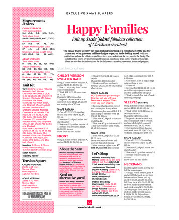
CCNA ExplorationLAN Switching and Wireless: LAN DesignLab 1.3.1: Review of Exploration 1Before proceeding, verify your IP addresses with the instructor.Task 2: Configure the Physical TopologyStep 1: Cable the network.Refer to the figure and table below for the necessary cables.CablingLAN cable between Host1 and Router1 Fa0/0LAN cable between Switch1 and Router1 Fa0/1LAN cable between Switch1 and Host2Console cable between Host1 and Router1Cable verFigure 1. Cabling the networkStep 2: Physically connect lab devices.Cable the network devices as shown in Figure 1. Turn power on to all devices if it is not already on.Step 3: Inspect the network connections.Verify the connections visually.Task 3: Configure the Logical TopologyStep 1: Configure the host computers.Configure the static IP address, subnet mask, and gateway for each host computer.Note: The following directions are for Windows XP. To configure hosts using other operating systems,refer to the operating system manual.To configure the host, go to Start Control Panel Network Connections Local AreaConnection. In the Local Area Connection Properties window, select Internet Protocol (TCP/IP) andclick the Properties button.All contents are Copyright 1992–2007 Cisco Systems, Inc. All rights reserved. This document is Cisco Public Information.Page 3 of 12
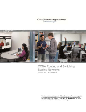
CCNA ExplorationLAN Switching and Wireless: LAN DesignLab 1.3.1: Review of Exploration 1Figure 2. Setting Properties for Internet Protocol (TCP/IP)In the TCP/IP Properties dialog box for each host, enter the IP address, network mask, andthe gateway from Table 1.After configuring each host computer, open a command window on the host by selectingStart Run. When prompted to type the name of a program, enter cmd in the text box. Fromthe command window, display and verify the host network settings with the ipconfig /allcommand. The settings should match those in the tables below:Host1 Network ConfigurationIP address192.168.7.1Subnet mask255.255.255.128Default gateway192.168.7.126Host2 Network ConfigurationIP address192.168.7.129Subnet mask255.255.255.192Default gateway192.168.7.190Are the host settings in agreement with the tables? If not, reconfigure as necessary.All contents are Copyright 1992–2007 Cisco Systems, Inc. All rights reserved. This document is Cisco Public Information.Page 4 of 12
CCNA ExplorationLAN Switching and Wireless: LAN DesignLab 1.3.1: Review of Exploration 1Step 2: Configure Router1.From Host1, connect to the console of Router 1 and establish a console session. Directions forcreating a console connection using HyperTerminal are in Appendix 2.From the router console, configure the following:TaskSpecificationRouter nameRouter1Encrypted privileged execpasswordciscoConsole access passwordclassTelnet access passwordclassRouter1 interface Fa0/0Set the descriptionSet the Layer 3addressRouter1 interface Fa0/1Set the descriptionSet the Layer 3addressEnter the following commands on the router:Router enableRouter#config termEnter configuration commands, one per line. End with CNTL/Z.Router(config)#hostname Router1Router1(config)#enable secret classRouter1(config)#line console 0Router1(config-line)#password )#line vty 0 4Router1(config-line)#password )#interface fa0/0Router1(config-if)#ip address 192.168.7.126 255.255.255.128Router1(config-if)#no shutdownRouter1(config-if)#description connection to host1Router1(config-if)#interface fa0/1Router1(config-if)#description connection to switch1Router1(config-if)#ip address 192.168.7.190 255.255.255.192Router1(config-if)#no shutdownRouter1(config-if)#endRouter1#Task 4: Verify Network ConnectivityStep 1: Use the ping command to verify network connectivity.You can verify network connectivity using the ping command.All contents are Copyright 1992–2007 Cisco Systems, Inc. All rights reserved. This document is Cisco Public Information.Page 5 of 12
CCNA ExplorationLAN Switching and Wireless: LAN DesignLab 1.3.1: Review of Exploration 1Note: If pings to the host computers fail, temporarily disable the computer firewall and retest. Todisable a Windows firewall, select Start Control Panel Windows Firewall, select OFF, and thenOK.Use the following table to verify connectivity with each network device. Take corrective action toestablish connectivity if a test fails.FromToIP AddressHost1NIC IP address192.168.7.1Host1Router1, Fa0/0192.168.7.126Host1Router1, Fa0/1192.168.7.190Host1Host2192.168.7.129Host2NIC IP address192.168.7.129Host2Router1, Fa0/1192.168.7.190Host2Router1, Fa0/0192.168.7.126Host2Host1192.168.7.1Ping ResultsIn addition to the ping command, what other Windows command is useful in displayingnetwork delay and breaks in the path to the destination?Task 5: Verify PasswordsStep 1: Telnet to the router from Host2 and verify the Telnet password.You should be able to telnet to either Fast Ethernet interface of the router.In a command window on Host 2, type:telnet 192.168.7.190When you are prompted for the Telnet password, type cisco and press Enter.Was the telnet successful?Step 2: Verify that the enable secret password has been set.From the Telnet session, enter privilege exec mode and verify it is password protected:Router enableWere you prompted for the enable secret password?Step 3: Verify that the console is password protected.Terminate and then re-establish the console connection from Host1 to the router to verify that theconsole is password protected.Depending on the Telnet client that you are using, the session can usually be terminated with Ctrl-].When the session is re-established, you should be prompted for the console password before beingallowed access to the command line interface.All contents are Copyright 1992–2007 Cisco Systems, Inc. All rights reserved. This document is Cisco Public Information.Page 6 of 12
CCNA ExplorationLAN Switching and Wireless: LAN DesignLab 1.3.1: Review of Exploration 1Task 6: ReflectionHow are Telnet access and console access different? When might it make sense to set differentpasswords on these two access ports?Why does the switch between Host2 and the router not require configuration with an IP address toforward packets?Task 7: Clean UpUnless directed otherwise by your instructor, erase the configurations and reload the switches.Disconnect and store the cabling. For PC hosts that are normally connected to other networks (suchas the school LAN or to the Internet), reconnect the appropriate cabling and restore the TCP/IPsettings.Final Router 1 ConfigurationRouter1#show run selective output omitted !hostname Router1!enable secret class!!interface FastEthernet0/0description connection to host1ip address 192.168.7.126 255.255.255.128no shutdown!interface FastEthernet0/1description connection to switch1ip address 192.168.7.190 255.255.255.192no shutdown!line con 0password ciscologinline aux 0line vty 0 4password ciscologin!endAll contents are Copyright 1992–2007 Cisco Systems, Inc. All rights reserved. This document is Cisco Public Information.Page 7 of 12
CCNA ExplorationLAN Switching and Wireless: LAN DesignLab 1.3.1: Review of Exploration 1Appendix 1: Last Octet Subnet ChartAll contents are Copyright 1992–2007 Cisco Systems, Inc. All rights reserved. This document is Cisco Public Information.Page 8 of 12
CCNA ExplorationLAN Switching and Wireless: LAN DesignLab 1.3.1: Review of Exploration 1Appendix 2: Creating a Router Console Session using HyperTerminalTask 1: Connect a Router and Computer with a Console CableStep 1: Set up a basic physical connection.Connect the console (rollover) cable to the console port on the router. Connect the other cable end to the host computer with a DB-9 or DB-25adapter to the COM 1 port.Step 2: Power on devices.If not already powered on, enable power to the computer and router.Task 2: Configure HyperTerminal to Establish a Console Session with a Cisco IOS RouterStep 1: Start the HyperTerminal application.Start the HyperTerminal program by clicking Start Programs Accessories Communications HyperTerminal.Step 2: Configure HyperTerminal.Figure 3. HyperTerminal Name Configuration WindowAll contents are Copyright 1992–2007 Cisco Systems, Inc. All rights reserved. This document is Cisco Public Information.Page 9 of 12
CCNA ExplorationLAN Switching and Wireless: LAN DesignLab 1.3.1: Review of Exploration 1In the Connection Description window, enter a session name in the Name field. Select an appropriate icon, or keep the default. Click OK.Figure 4. HyperTerminal Connection TypeEnter COM 1 in the Connect Using field, and then click OK. (Depending upon the PC you are using, it may be necessary to use a different COMport. If COM1 does not work, then systematically try the additional COM ports until you are successful.)All contents are Copyright 1992–2007 Cisco Systems, Inc. All rights reserved. This document is Cisco Public Information. Page 10 of 12
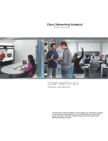
CCNA ExplorationLAN Switching and Wireless: LAN DesignLab 1.3.1: Review of Exploration 1Figure 5. HyperTerminal COM1 Port SettingsAs shown in Figure 3, change port settings to the following values, and then click OK:SettingBits per secondData bitsParityStop bitsFlow controlValue96008None1NoneWhen the HyperTerminal session window appears, press Enter. There should be a response from the router. This indicates that the connectionhas been successfully completed. If there is no connection, troubleshoot as necessary. For example, verify that the router has power. Check theconnection to the COM 1 port on the PC and the console port on the router. If there is still no connection, ask the instructor for assistance.All contents are Copyright 1992–2007 Cisco Systems, Inc. All rights reserved. This document is Cisco Public Information. Page 11 of 12
CCNA ExplorationLAN Switching and Wireless: LAN DesignLab 1.3.1: Review of Exploration 1Step 3: Close HyperTerminal.When finished, close the HyperTerminal session by choosing File Exit. When asked whether to save the session, click Yes. Enter a name forthe session.Step 4: Reconnect the HyperTerminal session.Reopen the HyperTerminal session as described in Task 2, Step 1. This time, when the Connection Description window appears (see Figure 3),click Cancel.Choose File Open. Select the saved session and then click Open. Use this step to reconnect the HyperTerminal session to a Cisco devicewithout reconfiguring a new session.When finished, exit HyperTerminal.All contents are Copyright 1992–2007 Cisco Systems, Inc. All rights reserved. This document is Cisco Public Information. Page 12 of 12
Lab 1.3.2: Review of Concepts from Exploration 1 - ChallengeTopology DiagramLearning ObjectivesUpon completion of this lab, you will be able to:Create a logical topology given network requirementsCreate subnets to meet host requirementsConfigure the physical topologyConfigure the logical topologyVerify network connectivityConfigure and verify passwordsScenarioIn this lab, you will design and configure a small routed network and verify connectivity across multiplenetwork devices. This requires creating and assigning two subnetwork blocks, connecting hosts andnetwork devices, and configuring host computers and one Cisco router for basic network connectivity.Switch1 has a default configuration and does not require additional configuration. You will use commoncommands to test and document the network. The zero subnet is used.All contents are Copyright 1992–2007 Cisco Systems, Inc. All rights reserved. This document is Cisco Public Information.Page 1 of 5
CCNA ExplorationLAN Switching and Wireless: LAN DesignLab 1.3.2: Review of Exploration 1 - ChallengeTask 1: Design a Logical LAN TopologyStep 1: Design an IP addressing scheme.Given the IP address block of 192.168.30.0 /27, design an IP addressing scheme that satisfies thefollowing requirements:SubnetSubnet ASubnet BNumber of Hosts714The 0 subnet is used. No subnet calculators may be used. Create the smallest possible number ofsubnets that satisfy the requirements for hosts. Assign the first usable subnet to Subnet A.Subnet ASpecificationStudent InputNumber of bits in the subnetIP mask (binary)New IP mask (decimal)Maximum number of usablesubnets (including the 0 subnet)Number of usable hosts persubnetIP subnetwork addressFirst IP host addressLast IP host addressSubnet BSpecificationNumber of bits in the subnetIP mask (binary)New IP mask (decimal)Maximum number of usable subnets(including the 0 subnet)Number of usable hosts per subnetIP subnetwork addressFirst IP host addressLast IP host addressStudent InputHost computers will use the first usable IP address in the subnet. The network router will use the lastusable IP address in the subnet.Step 2: Write down the IP address information for each P addressMaskGatewayAll contents are Copyright 1992–2007 Cisco Systems, Inc. All rights reserved. This document is Cisco Public Information.Page 2 of 5
CCNA ExplorationLAN Switching and Wireless: LAN DesignLab 1.3.2: Review of Exploration 1 - ChallengeBefore proceeding, verify your IP addresses with the instructor.Task 2: Configure the Physical TopologyStep 1: Determine cabling requirements.Referring to Figure 1, identify each cable type required and document it in the table.Correct CablingLAN cable between Host1 and Router1 Fa0/0LAN cable between Switch1 and Router1 Fa0/1LAN cable between Switch1 and Host2Console cable between Host1 and Router1Cable TypeFigure 1. Cabling the network.Step 2. Physically connect lab devices.Cable the network devices as shown in Figure 1. Turn power on to all devices if it is not already on.Step 3: Inspect the network connections.After cabling the network devices, verify the connections.Task 3: Configure the Logical TopologyStep 1: Configure the host computers.Configure the static IP address, subnet mask, and gateway for each host computer. After configuringeach host computer, display and verify the host network settings with the ipconfig /all command.All contents are Copyright 1992–2007 Cisco Systems, Inc. All rights reserved. This document is Cisco Public Information.Page 3 of 5
CCNA ExplorationLAN Switching and Wireless: LAN DesignLab 1.3.2: Review of Exploration 1 - ChallengeHost1 Network ConfigurationPhysical addressIP addressSubnet maskDefault gatewayHost2 Network ConfigurationPhysical addressIP addressSubnet maskDefault gatewayStep 2: Configure Router1.From Host1, connect to the console of Router 1 and configure the following:TaskSpecificationRouter nameRouter1Encrypted privileged exec passwordclassConsole access passwordciscoTelnet access passwordciscoRouter1 interface Fa0/0Set the descriptionSet the Layer 3 addressRouter1 interface Fa0/1Set the descriptionSet the Layer 3 addressTask 4: Verify Network ConnectivityStep 1: Use the ping command to verify network connectivity.You can verify network connectivity using the ping command.Note: If pings to the host computers fail, verify the existence of a firewall program running on the hosts. Ifa firewall is running on the host temporarily disable it and retest. To disable a Windows firewall, selectStart Control Panel Windows Firewall, select OFF, and then OK.Use the following table to verify connectivity with each network device. Take corrective action to establishconnectivity if a test fails.FromToHost1NIC IP addressHost1Router1, Fa0/0Host1Router1, Fa0/1Host1Host2Host2NIC IP addressIP AddressPing ResultsAll contents are Copyright 1992–2007 Cisco Systems, Inc. All rights reserved. This document is Cisco Public Information.Page 4 of 5
CCNA ExplorationLAN Switching and Wireless: LAN DesignHost2Router1, Fa0/1Host2Router1, Fa0/0Host2Host1Lab 1.3.2: Review of Exploration 1 - ChallengeIn addition to the ping command, what other Windows command is useful in displaying network delayand breaks in the path to the destination?Task 5: Verify PasswordsStep 1: Telnet to the router from Host2 and verify the Telnet password.You should be able to telnet to either Fast Ethernet interface of the router.Step 2: Verify that the enable secret password has been set.From the Telnet session, enter privilege exec mode and verify that it is password protected.Step 3: Verify that the console is password protected.Terminate and then re-establish the console connection from Host1 to the router to verify that the consoleis password protected.Depending on the Telnet client that you are using, the session can usually be terminated with Ctrl-].Task 6: Clean UpUnless directed otherwise by your instructor, erase the configurations and reload the switches.Disconnect and store the cabling. For PC hosts that are normally connected to other networks (such asthe school LAN or to the Internet), reconnect the appropriate cabling and restore the TCP/IP settings.All contents are Copyright 1992–2007 Cisco Systems, Inc. All rights reserved. This document is Cisco Public Information.Page 5 of 5
Lab 1.3.3: Troubleshooting a Small NetworkTopology DiagramLearning ObjectivesUpon completion of this lab, you will be able to:Verify that a paper design meets stated network requirementsCable a network according to the topology diagramErase the startup configuration and reload a router to the default stateLoad the routers with supplied scriptsDiscover where communication is not possibleGather information about the misconfigured portion of the network along with any other errorsAnalyze information to determine why communication is not possiblePropose solutions to network errorsImplement solutions to network errorsScenarioIn this lab, you are given a completed configuration for a small routed network. The configuration containsdesign and configuration errors that conflict with stated requirements and prevent end-to-endcommunication. You will examine the given design and identify and correct any design errors. You willthen cable the network, configure the hosts, and load configurations onto the router. Finally, you willtroubleshoot the connectivity problems to determine where the errors are occurring and correct themAll contents are Copyright 1992–2007 Cisco Systems, Inc. All rights reserved. This document is Cisco Public Information.Page 1 of 5
CCNA ExplorationLAN Switching and Wireless: LAN DesignLab 1.3.3: Troubleshooting a Small Networkusing the appropriate commands. When all errors have been corrected, each host should be able tocommunicate with all other configured network elements and with the other host.Task 1: Examine the Logical LAN TopologyThe IP address block of 172.16.30.0 /23 is subnetted to meet the following requirements:SubnetSubnet ASubnet BNumber of Hosts17460Additional requirements and specifications:The 0 subnet is used.The smallest possible number of subnets that satisfy the requirements for hosts should be used,keeping the largest possible block in reserve for future use.Assign the first usable subnet to Subnet A.Host computers use the first IP address in the subnet. The network router uses the last networkhost address.Based on these requirements, the following topology has been provided to you:Subnet ASpecificationIP mask (decimal)IP addressFirst IP host addressLast IP host .16.30.254Subnet BSpecificationIP mask (decimal)IP addressFirst IP host addressLast IP host 72.16.31.126Examine each of the values in the tables above and verify that this topology meets all requirements andspecifications. Are any of the given values incorrect?If yes, correct the values in the table above and write the corrected values below:Create a configuration table similar to the one below using your corrected values:DeviceHost1Router1–Fa0/0Host2IP .30.254N/A172.16.31.126All contents are Copyright 1992–2007 Cisco Systems, Inc. All rights reserved. This document is Cisco Public Information.Page 2 of 5
CCNA ExplorationLAN Switching and Wireless: LAN DesignRouter1–Fa0/1Lab 1.3.3: Troubleshooting a Small Network172.16.31.126255.255.255.128N/ATask 2: Cable, Erase, and Reload the RoutersStep 1: Cable the network.Cable a network that is similar to the one in the topology diagram.Step 2: Clear the configuration on each router.Clear the configuration on the router using the erase startup-config command and then reload therouter. Answer no if asked to save changes.Task 3: Configure the Host ComputersStep 1: Configure host computers.Configure the static IP address, subnet mask, and gateway for each host computer based on theconfiguration table created in Task 1. After configuring each host computer, display and verify the hostnetwork settings with the ipconfig /all command.Task 4: Load the Router with the Supplied Scriptsenable!config term!hostname Router1!enable secret class!no ip domain-lookup!interface FastEthernet0/0description connection to host1ip address 172.16.30.1 255.255.255.0duplex autospeed auto!interface FastEthernet0/1description connection to switch1ip address 192.16.31.1 255.255.255.192duplex autospeed auto!!line con 0password ciscologinline vty 0loginAll contents are Copyright 1992–2007 Cisco Systems, Inc. All rights reserved. This document is Cisco Public Information.Page 3 of 5
CCNA ExplorationLAN Switching and Wireless: LAN DesignLab 1.3.3: Troubleshooting a Small Networkline vty 1 4password ciscologin!endTask 5: Identify Connectivity ProblemsStep 1: Use the ping command to test network connectivity.Use the following table to test the connectivity of each network device.FromToIP AddressHost1NIC IP addressHost1Router1, Fa0/0172.16.30.1172.16.30.254Host1Router1, Fa0/1172.16.31.126Host1Host2172.16.31.1Host2NIC IP address172.16.30.1Host2Router1, Fa0/1172.16.31.126Host2Router1, Fa0/0172.16.30.254Host2Host1172.16.30.1Ping ResultsTask 6: Troubleshoot Network ConnectionsStep 1: Begin troubleshooting at the host connected to the BRANCH router.From host PC1, is it possible to ping PC2?From host PC1, is it possible to ping the router fa0/1 interface?From host PC1, is it possible to ping the default gateway?From host PC1, is it possible to ping itself?Where is the most logical place to begin troubleshooting the PC1 connection problems?Step 2: Examine the router to find possible configuration errors.Begin by viewing the summary of status information for each interface on the router.Are there any problems with the status of the interfaces?All contents are Copyright 1992–2007 Cisco Systems, Inc. All rights reserved. This document is Cisco Public Information.Page 4 of 5
CCNA ExplorationLAN Switching and Wireless: LAN DesignLab 1.3.3: Troubleshooting a Small NetworkIf there are problems with the status of the interfaces, record any commands that are necessary to correctthe configuration errors.Step 3: Use the necessary commands to correct the router configuration.Step 4: View a summary of the status information.If any changes were made to the configuration in the previous step, view the summary of the statusinformation for the router interfaces.Does the information in the interface status summary indicate any configuration errors on Router1?If the answer is yes, troubleshoot the interface status of the interfaces.Has connectivity been restored?Step 5: Verify the logical configuration.Examine the full status of Fa 0/0 and 0/1. Is the IP addresses and subnet mask information in theinterface status consistent with the configuration table?If there are differences between the configuration table and the router interface configuration, record anycommands that are necessary to correct the router configuration.Has connectivity been restored?Why is it useful for a host to ping its own address?Task 7: Clean UpUnless directed otherwise by your instructor, erase the configurations and reload the switches.Disconnect and store the cabling. For PC hosts that are normally connected to other networks (such asthe school LAN or to the Internet), reconnect the appropriate cabling and restore the TCP/IP settings.All contents are Copyright 1992–2007 Cisco Systems, Inc. All rights reserved. This document is Cisco Public Information.Page 5 of 5
CCNA Exploration LAN Switching and Wireless: LAN Design Lab 1.3.1: Review of Exploration 1 Step 2: Configure Router1. From Host1, connect to the console of Router 1 and establish a console session. Directions for creating a console connection using HyperTerminal are in Appendix 2. From the router console, configure the following: Task Specification