Transcription
58MVPVariable-Speed 2-StageElectronic Condensing FurnaceVisit www.carrier.comTroubleshooting GuideINDEXPAGEInstructions .1Example .1Sequence of Operation.2-4Self-Test Mode.2Heating Mode.2Heating Mode-Two Stage.2Emergency Heat Mode.2-3Cooling Mode .3Heat Pump Mode .3Continuous Fan Mode .4Component Test .4Bypass Humidifier Mode.4Dehumidification Mode.4-5Zone Mode .5Start Here.6Improper Operation With No Flashing Fault Code .7Service Label/Fault Code Instructions .8-9Not Enough Cooling Airflow .10High-Fire Temperature Rise Too Low (Cold Blow) .11LEDs 1, 2, 3, or 4 On Solid.11-12RED LED2 Flashing .12Fault Code 11—No Fault in Recent History Display .13Fault Code 12—Blower Calibration Lockout.13-14Fault Code 13—Limit Switch Lockout.15-16Fault Code 14—Ignition Lockout .16-17Fault Code 21—Invalid Model Selection.17Fault Code 22—Set Up Error.17Fault Code 23—Invalid Blower Airflow Selection.18-19Fault Code 24—Secondary Voltage Fuse Is Open.19-20Fault Code 31—High-Pressure Switch Fault.20-21Fault Code 32—Low-Pressure Switch Fault .22-23Fault Code 33—Limit Switch Fault.23-24Fault Code 34—Ignition Proving Fault .25-26Fault Code 41—Blower Outside Valid Speed Range .26Fault Code 42—Inducer Outside Valid Speed Range.27-28Fault Code 43—Pressure Switch Calibration Fault.28-29Fault Code 44—Blower Calibration Fault.29-30Cleanup and Start-Up Instructions .30APPENDIX A—Board Layout & Wiring Schematic .31-32APPENDIX B—Isolation Circuits .33APPENDIX C—Pressure Check Diagram .33APPENDIX D—Quick Motor Test Procedure .34-35APPENDIX E—Variable-Speed Condensing Furnace DuctStatic and Blower Operation.36-40APPENDIX F—Quick Reference Information .41APPENDIX G—Thermostat Staging Algorithm .42-43INSTRUCTIONSThis guide uses your expertise and observations to lead you to thetrouble spot as efficiently as possible. This is only intended as aguide and should not be used blindly. Your experience andexpertise are of high value when troubleshooting this unit. Do notdisregard all of your instincts.The microprocessor furnace control was designed with diagnosticcapabilities built in. LEDs are used to flash a fault code which willlead you to 1 of the subsections as listed in the Index.You should ALWAYS begin in the START HERE subsection(see Index for page number) which will guide you to theappropriate subsection where a minimal number of steps will beused to correct the problem. If you are very experienced at howthis furnace operates and you suspect the problem is either theblower motor, inducer motor, or furnace control board, you can usethe quick motor test procedure at the end of the troubleshootingguide to isolate the problem or direct you to appropriate section inmain troubleshooting guide.Once in a subsection, read the statement or question. A statementwill have a number in the "GO TO" column. Do whatever thestatement says, then proceed to step indicated in the "GO TO"column.If the step is a question (a question will have a number in the"YES" or "NO" column), answer it "YES" or "NO." If the answeris "YES," go to step indicated in "YES" column. If the answer is"NO," go to step indicated in "NO" column.Let’s try our guide out using the EXAMPLE section below, andsee how it works. Suppose that the problem is a defectivelow-pressure switch (for example will not make). This is aninternal problem and cannot simply be seen. We go to the STARTHERE section to Step 1.EXAMPLEStart Here SectionSTEP1.2.5.7.Step 1 tells us to record status of LEDs 1-4 and go to Step 2.Step 2 asks the question, "Are any LEDs flashing?". If low-pressure switch was defective, a lowpressure switch fault code would be flashing, so the answer is "YES." We go to Step 5.Step 5 asks the question, "Is RED LED2 flashing?". If low-pressure switch was defective, a lowpressure switch fault code would be flashing, so the answer is "NO". We go to Step 7.Step 7 tells us to go to low-pressure switch fault subsection.YES—NO—GO TO253—67———INDEXManufacturer reserves the right to discontinue, or change at any time, specifications or designs without notice and without incurring obligations.Book 1 4PC 101Catalog No. 565-829Printed in U.S.A.Form 58MVP-6SMPg 17-98Replaces: 58MVP-1SMTab 6a 8a
SEQUENCE OF OPERATIONThe reduction in speed in low heat is to optimize combustionfor maximum efficiency.7. Blower on delay—The blower starts 60 sec after flame senseif cycle started in low heat or 35 sec after flame sense if cyclestarted in high heat.Furnace control must be grounded for proper operation, orcontrol will lock out. Control is grounded through green wirerouted to gas valve and burner box screw.NOTE: The blower starts at approximately 400-500 RPM. After20 sec, the motor is turned off for 1/10 of a sec where a coast downcalibration is done to evaluate resistance of the conditioned airduct system. The microprocessor then determines blower RPMrequired to provide proper airflow for heating mode.Using schematic diagram (see Appendix A), follow sequence ofoperation through different modes. This furnace has a new controlsystem. Read and follow wiring diagram carefully.NOTE: If 115-v power supply to furnace or blower access panelswitch is interrupted during a call for heat, blower operates atlow-heat speed for 60 sec when power is restored before heatingcycle is resumed.8. Electronic Air Cleaner—The EAC-1 terminal is energizedwhenever the blower operates.9. Blower off delay—When thermostat is satisfied, the R-W/W1signal is terminated, de-energizing gas valve (stopping gasflow to burners) and HUM terminal is de-energized.Step 1—Self-Test ModeThe control center goes through a brief self test whenever 115-v or24-v power is interrupted. The self test takes approximately 2 secto complete. After power is restored, red (microprocessor) LEDbriefly comes on. Then green LED comes on for 1 sec, followed by1 sec where both yellow and green LEDs are on. During this time,the microprocessor is checking itself.The blower reduces its speed to low-heat RPM. The blowerand EAC remain operating 90, 135, 180, or 225 sec (depending on blower off time selection). The furnace is factory set fora 90 sec blower off delay.10. Post purge—The inducer continues operating for 15 sec aftergas valve is de-energized.Step 2—Heating ModeWhen thermostat calls for heat, R-W/W1 circuit closes.Step 3—Heat Mode—Two Stage1. Prepurge period—The inducer motor is turned on and slowlycomes up to speed. When low-pressure switch closes, inducermotor RPM is noted by microprocessor, and a 25 sec prepurgeperiod begins. The RPM is used to evaluate vent systemresistance. This evaluation is then used to determine requiredRPM necessary to operate inducer in low-heat mode.NOTE: The heat cycle can start in either high or low heat. If ahigh-heat cycle is initiated, the inducer continues increasing itsspeed after low-pressure switch closes. When high-pressure switchcloses, inducer motor RPM is noted by microprocessor before the25 sec prepurge period begins. The RPM is used to evaluate ventsystem resistance. This evaluation is then used to determinerequired RPM necessary to operate inducer in high-heat mode.The control center provides 2-stage heating using a single-stagethermostat. The control center maximizes comfort while optimizing efficiency to meet the demands of the conditioned area whena thermostat R-W/W1 signal is received.If thermostat control over furnace staging is desired, a 2-stagethermostat can be used. When control center receives a thermostatR-W/W1 and R-W2 signal, high heat is energized and whenR-W/W1 signal is received, low heat is energized. This methodoverrides microprocessor control of high or low heat.NOTE: When using 2-stage thermostat operation with R-W/W1and R-W2 signals, setup switch SW-2 MUST be in ON position.The heat cycle operates as stated in Heating Mode section.2. Humidifier (HUM)—The HUM terminal is energized whenever the inducer prepurge period is completed.To allow for greater comfort, a 2-stage thermostat control isrecommended when zone systems are used.3. Ignitor warm up—At end of prepurge period, the hot surfaceignitor (HSI) is energized for a 17-sec HSI warm-up period.Step 4—Emergency Heat Mode4. Ignition sequence—After HSI ignitor warm-up period iscompleted, the gas valve opens, permitting gas flow to burnerswhere it is ignited. After 5 sec, the HSI is de-energized and a2-sec flame-sensing period begins.NOTE: The initial heat mode after 115-v or 24-v power interruption will be LOW HEAT. Low heat remains energized for 16minutes before high heat is initiated, providing thermostat is stillcalling for heat.NOTE: The furnace should not be operated in emergency heatmode for extended periods of time. Operation is only recommended to provide heat until replacement components can beobtained or fault resolved.In this mode, the microprocessor is bypassed and the motorsoperate at full speed with high-heat operation. The heat exchangers, motors, and electronics can be overstressed and may reducethe life of the components if operated for an extended period.After the initial cycle, the microprocessor evaluates the length oflow- and high-heat operating times and calculates optimum lengthof low and high heat for next heat cycle. This accommodates theheat load requirement seen as a result of thermostat operating time.See Appendix G for details on thermostat staging algorithm.NOTE: No safeties are bypassed when using emergency heatmode.Emergency heat mode can be selected using setup switch SW-4.SW-4 should be used when a fault condition exists or difficult toresolve problems occur. This allows heating until the fault can becorrected.5. Flame sensing—When burner flame is sensed, the controlcenter holds gas valve open and begins blower on delayperiod.NOTE: Ignition sequence repeats 3 additional times before alockout occurs. Lockout automatically resets after 3 hr, or can bemanually reset by turning 115-v or 24-v power off (not atthermostat) for 3 sec minimum, then turning on again.In emergency heat mode, the normal heat mode outlined inHeating Mode section is not followed. The following sequencewill occur:When thermostat calls for heat, the R-W/W-1 circuits close.1. Prepurge period—The inducer motor is turned on IMMEDIATELY operating at maximum speed, closing low- andhigh-pressure switches. Prepurge begins 25 sec after highpressure switch closes.6. Inducer speed reduction—If cycle starts in low heat, inducerspeed reduces slightly after the flame sense. If cycle starts inhigh heat, inducer speed increases 15 sec after flame sense.2
thermidistat or humidistat for dehumidification purposes.2. Blower on—The blower motor is turned on IMMEDIATELYand slowly increases to maximum speed as soon as a call forheat is received. No blower calibration occurs.Step 6—Heat Pump ModeWhen furnace is operating in heat pump heating mode, R-Y/Y2and R-G circuits are closed energizing heat pump, and bloweroperates at cooling speed. When heat pump defrost is required,R-W/W1 circuits close starting gas heat cycle, and blower adjuststo low-heat speed.3. Electronic Air Cleaner—The EAC-1 terminal does notoperate in emergency heat mode.4. Humidifier—The HUM terminal is energized IMMEDIATELY.1. Prepurge period—The inducer motor is turned on and slowlycomes up to speed. When low-pressure switch closes, inducermotor RPM is noted by microprocessor, and a 25 sec prepurgeperiod begins. The RPM is used to evaluate vent systemresistance. This evaluation is then used to determine requiredRPM necessary to operate inducer in low-heat mode.5. Ignitor warm up—The HSI is energized for a 17 secwarm-up period after prepurge period is completed.6. Ignition sequence—After HSI warm-up period has completed, the gas valve is energized, permitting gas flow toburners where it is ignited. After 5 sec, the HSI is de-energizedand a 2-sec flame-sensing period begins.NOTE: The heat cycle can start in either high or low heat. If ahigh-heat cycle is initiated, inducer continues increasing its speedafter low-pressure switch closes. When high-pressure switchcloses, inducer motor RPM is noted by microprocessor before the25 sec prepurge period begins. The RPM is used to evaluate ventsystem resistance. This evaluation is used to determine requiredRPM necessary to operate inducer in high-heat mode.NOTE: Emergency heat mode only operates in high heat.7. Flame sensing—When burner flame is sensed, control centerholds gas valve open. If burner flame is not sensed, controlcenter de-energizes gas valve and ignition sequence is repeated.NOTE: Ignition sequence repeats 3 additional times before lockout occurs. Lockout automatically resets after 3 hr, or can bemanually reset by turning 115-v or 24-v power off (not atthermostat) for 3 sec minimum, then turning on again. Fault codeswill not flash in emergency heat mode.2. Humidifier—The HUM terminal is energized whenever inducer prepurge period is completed.3. Ignitor warm up—After prepurge period, HSI is energizedfor 17 sec.8. Blower off delay—When thermostat is satisfied, the R-W/W1signal is terminated, de-energizing gas valve (stopping gasflow to burners) and HUM terminal is de-energized. Inaddition, blower stops immediately.4. Ignition sequence—After HSI warm-up period is completed,the gas valve is energized, permitting gas flow to the burnerswhere it is ignited. After 5 sec, the HSI is de-energized and a2-sec flame-sensing period begins.9. Post purge—Post purge does NOT occur. The inducer stopsimmediately.5. Flame sensing—When burner flame is sensed, control centerholds gas valve open.Step 5—Cooling ModeIf burner flame is not sensed, control center de-energizes gasvalve and ignition sequence is repeated.When thermostat calls for cooling, the R-G and R-Y/Y2 circuitsclose.6. Blower off period—Ten sec after gas valve is energized, theblower stops for 25 sec to allow heat exchangers to warm up.1. Cooling unit—The cooling unit starts when thermostat R-Ysignal is received.7. Blower on delay—After blower off period, blower starts.2. Blower on—The control center starts blower immediatelywhen it receives an R-Y/Y2 and R-G signal. The blower startsat approximately 400-500 RPM. After 20 sec, the blower isturned off for 1/10 of a sec where a coast down calibration isdone to evaluate resistance of the conditioned air duct system.The microprocessor then determines blower RPM required toprovide selected cooling airflow.NOTE: The blower starts at approximately 400-500 RPM. After20 sec, the motor is turned off for 1/10 of a sec where a coast downcalibration is done to evaluate resistance of the conditioned airduct system. The microprocessor then determines blower RPMrequired to provide proper airflow for heating mode.In cooling mode, the microprocessor adjusts blower RPMto operate at 400 CFM per ton as selected on the A/C setupswitches. Airflow will be reduced to 340 or 315 CFM per ton,depending on board style (See Fig. 1), when a dehumidificationdemand exists. See Air Conditioning Setup Switches section inInstallation, Start-Up and Operating Instructions for details. Thereis also a chart on schematic in Appendix A.9. Inducer speed reduction—If cycle starts in low heat, inducerspeed reduces slightly after the flame sense. If cycle starts inhigh heat, inducer speed increases 15 sec after flame sense.The reduction in speed in low heat is to optimize combustionfor maximum efficiency.8. Electronic Air Cleaner—The EAC-1 terminal is energizedwhenever blower operates. NOTE: NOTE: If Y/Y2 thermostat lead is not connected to furnacecontrol center, blower motor operates in continuous fan speed andindoor coil freeze-up may occur.10. Call for heat terminated—When the call for heat is satisfied,the R-W/W1 signal is terminated, de-energizing gas valve(stopping gas flow to burners) and HUM terminal is deenergized.3. Electronic Air Cleaner—The EAC-1 terminal is energizedwhenever blower operates.a. R-W/W1 signal terminated with R-Y/Y2 and R-G stillpresent—The blower changes its speed to cooling RPM.4. Cooling unit—The cooling unit stops when thermostat R-Ysignal is terminated.b. R-W/W1 with R-Y/Y2 and R-G signals terminated—The blower continues to operate completing a normalblower off delay.5. Blower off delay—When thermostat is satisfied, the R-Y/Y2and R-G signals are terminated, and blower remains operatingfor 90 sec. On newer style control boards (See Fig. 1), theblower airflow will drop by 21 percent during the off-delayperiod when the DE jumper is connected. The DE jumper isonly removed to enable the DEHUM input for use with a11. Post purge—The inducer continues operating for 15 sec aftergas valve is de-energized.3
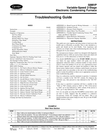
Step 7—Continuous Fan ModeWhen items 1-5 have been completed, the following will occur:1. Operating with continuous fan only.1. The control center goes through a brief self test. This self testtakes approximately 2 sec to complete. After door switch isclosed, red (microprocessor) LED briefly comes on. Thengreen LED comes on for 1 sec, followed by 1 sec where bothgreen and yellow LEDs are on. During this time, the microprocessor is checking itself.a. Call for continuous fan—The thermostat closes R-Gcircuit.b. Blower on—The blower starts immediately.NOTE: The blower starts at approximately 400-500 RPM. After20 sec, the motor is turned off for 1/10 of a sec where a coast downcalibration is done to evaluate resistance of the conditioned airduct system. The microprocessor then determines blower RPMrequired to provide proper airflow for heating mode.2. Inducer motor operates for 20 sec at low speed, operates 20sec at high speed, then turns off.3. Hot surface ignitor is energized for 15 sec, then de-energized.NOTE: The continuous fan speed is the same as low-heat speedunless it is field adjusted to another desired airflow. See Continuous Fan Setup Switches section in Installation, Start-Up, andOperating Instructions for details. There is also a chart onschematic diagram shown in Appendix A.4. Main blower motor operates for 20 sec at low speed, operatesfor 20 sec at high speed, then turns off.c. Electronic Air Cleaner—The EAC-1 terminal is energized whenever blower operates, regardless of operatingmode.NOTE: To repeat component test, turn setup switch SW-6 to OFFand then back to ON.2. Operating with continuous fan (R-G) and call for heat(R-W/W1) is received—Same as heat pump mode exceptblower on delay is 10 sec less than the heat mode. After callfor heat (R-W/W1) is terminated, the blower remains operating at low-heat speed for selected blower off delay beforeresuming continuous fan speed.1. Release blower panel access door switch and turn setup switchSW-6 to OFF position.5. After component operation test is completed, 1 or more faultcodes (11, 22, 41, or 42) will flash. See service label on backof main furnace door or Fig. 1 for explanation of fault codes.After component test, perform the following:2. If applicable, replace blower access panel and check LEDstatus by removing plug in blower access panel.3. Reinstall main furnace door if all LEDs are off, indicatingfurnace is ready to operate when a signal from thermostat isreceived.3. Operating with continuous fan (R-G) and call for cooling(R-Y/Y2) is received—See Cooling Mode section. After callfor cooling (R-Y/Y2) is terminated, the blower remainsoperating at cooling speed for 90 sec before resuming continuous fan speed.Step 9—Bypass Humidifier ModeWhen setup switch SW-3 BPH is in ON position, RPM calculatedfor low heat is multiplied by 1.15 for all furnace model sizes. Thiscompensates for increased return-air temperature caused by bypassed air supply.Step 8—Component TestAll components are functionally operated except gas valve withcomponent test feature. Step 10—Dehumidification ModeThis feature helps diagnose a system problem in case of acomponent failure.A dehumidification input is provided via a 1/4-in. male quickconnect terminal labeled DEHUM located next to the transformersecondary connections. The DEHUM input acts differently depending on which style of variable speed furnace control you have.NOTE: Setup switch SW-1 MUST be in OFF position or FaultCode 22 (setup error) will occur.The older style variable speed furnace control (shown in Fig. 1),DOES NOT have a DE connection, while the newer style variablespeed furnace control (shown in Fig. 1), has a DE connection. Thenewer style variable speed furnace control is expected to beavailable by mid 1998. Both of these variable speed furnacecontrols function the same except the DEHUM logic is reversed.This logic reversal has come about from historical use of astandard humidistat to do dehumidification since the contacts openon high humidity, thus removing the 24-v signal to initiatedehumidification.NOTE: NO thermostat signal may be present at control center,and all blower time delay off periods must be completed.To initiate component test feature, proceed with the following:1. Leave 115-v power to furnace turned on.2. Remove main furnace door.3. Remove blower access panel.4. Turn setup switch SW-6 to ON position.5. Manually close blower access panel door switch.On the older style variable speed furnace controls, a field suppliedrelay is required between the thermidistat or humidistat control andfurnace. The relay coil is connected between DHUM output on thethermidistat control and COM terminal on the furnace control or thehumidistat output and COM terminal on the furnace control (SeeFig. 1 and Fig. 2). When a dehumidify demand exists, relay isde-energized, and normally closed contacts supply 24-v to thefurnace DEHUM terminal. As a result, the furnace control reducesthe blower airflow by 15 percent to 340 CFM per ton duringcontinuous fan or cooling operation.On some models, blower access panel door switch opens only24-v power to control center. No component operation canoccur. The 115-v power is still present at control center,transformer, inducer motor, and main blower motor. Cautionmust be taken when manually closing this switch for servicepurposes. Failure to follow this warning could result inpersonal injury or death.On newer style variable speed furnace controls, a field suppliedrelay IS NOT required. The DHUM output on the thermidistatcontrol or the humidistat output is connected directly to theDEHUM terminal on the furnace control. In addition, the DEjumper located next to the DEHUM terminal must be removed toenable the DEHUM input. (See Fig. 1 and Fig. 3). When a4
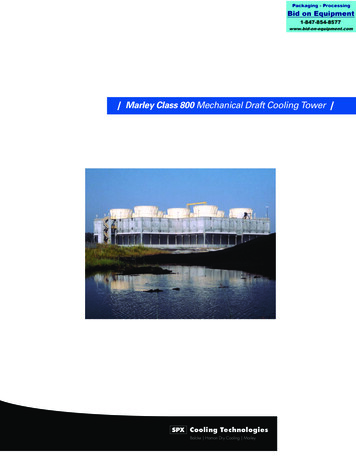
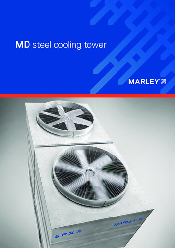
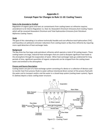
HUMW2Com W/W124VY/Y2RGHUMGRY/Y2Com W/W124VW2WITHOUT DECONNECTIONDEHUMSEC-1SEC-2SEC-1DEHUMSEC-2DEDE CONNECTIONWITH DECONNECTIONA98293 Fig.1—Variable Speed Furnace ControlTHERMIDISTAT24 VAC HOTRVARIABLE-SPEEDCONDENSINGFURNACETHERMIDISTATR24 VAC HOTDEHUMIDIFY DHUMDEHUMDEHUMIDIFY DHUM24 VAC E 1C24 VAC COMMCComNOTE 1 - Remove DE ConnectionTo Enable DEHUM InputA98294 Fig. 2—Without DE ConnectionA98295dehumidify demand exists, the furnace control reduces the blowerairflow by 21 percent to 315 CFM per ton during continuous fanor cooling operation.This blower speed reduction compensates for high humidityconditions during cooling operation on all furnace model sizes.Reference Thermidistat Control Installation, Start-Up, and Operating Instructions for further details.Step 11—Zone ModeWhen setup switch SW-5 MZ is in ON position, blower motorcontrol is the same as above except with the following exceptions:1. While blower is operating in either low heat or continuous fan,the coast down calibration is performed once a minute toupdate blower RPM for zone damper position changes duringa given cycle. Fig. 3—With DE ConnectionNOTE: Boards with date codes of 9506 or later will not performa coast down calibration if blower pulse width to blower motor isgreater than 60 percent. This prevents nuisance faults fromoccurring when a high continuous fan CFM has been selected.2. While blower is operating in either high heat or cooling,blower pulse width to blower motor is frozen when blowerRPM is within 10 percent of calculated blower RPM for 5 sec.5
START HERE—If a problem exists, the service technician should always begin troubleshooting here. Remove main furnace door first. DO NOT REMOVE BLOWER ACCESS PANEL! Record status ofLEDs 1-4. See Service Label/Fault Code Instructions (Fig. 4).Are any LEDs flashing?Are any LEDs on solid? (Solid means ON continuously.)Go to page number indicated in Index for LEDs 1, 2, 3, or 4 ON SOLID.Is RED LED2 flashing?Go to page number indicated in Index for RED LED2 FLASHING.Go to page number indicated in Index for subsection covering fault code being flashed.Is power on? (DO NOT cycle power to unit).Turn power on.Remove blower access panel and depress door switch. Use a piece of tape to hold switch closed.Wait a few sec for self test before proceeding to next step.Does problem appear to be low cooling airflow?Go to page number indicated in Index for subsection covering NOT ENOUGH COOLING AIRFLOW.Make sure thermostat is calling for heat.Make sure thermostat fan control is in AUTO position if equipped.Observe operation of furnace for 20 minutes or until fault occurs.Does a fault occur?Is temperature rise below range specified on rating plate when unit is running in high fire?Go to page number indicated in Index for subsectioncovering HIGH FIRE TEMPERATURE RISE TOO LOW (COLD BLOW).Does furnace operate properly?Remove blower access panel and depress door switch. Use a piece of tape to hold switch closed.Wait a few sec for self test before proceeding to next step.Disconnect R thermostat lead, then wait until blower motor stops.Are any LEDs flashing?Are any LEDs on solid? (Solid means ON continuously.)Is RED LED2 flashing?Put setup switch SW-1 in ON position.Record fault codes listed in fault history.NOTE: Read fault codes until they repeat. The last fault code that occurred will flash first followed by the lowest number fault code. (EXAMPLE: 13, 13, 44)Are LEDs 3 and 4 flashing a Fault Code 11?Go to page number indicated in Index for subsection covering NO OPERATION WITH NO FLASHING FAULT CODE.Go to page number indicated in Index for CLEANUP AND START-UPINSTRUCTIONS.Go to page number indicated in Index for subsection covering first fault code flashed.Disconnect the R thermostat lead, then wait until blower motor stops.Put setup switch SW-1 in ON position.Record fault codes listed in fault history.NOTE: Read fault codes until they repeat. The last fault code that occurred will flash first followed by the lowest number fault code. (EXAMPLE: 13, 13, 44)Are LEDs 3 and 4 flashing a Fault Code 11?Go to page number indicated in Index for the CLEANUP AND START-UPINSTRUCTIONS. If this problem persists on an intermittent basis, replace furnace control board. Ifproblem still persists on an intermittent basis after replacing furnace control board, contact your distributor.6YESNOGO NDEX3233——343530———INDEX
IMPROPER OPERATION WITH NO FLASHING FAULT CODE—Generally, this indicates there is no power tofurnace control 34.35.36.37.38.39.40.Make sure power is on.Remove blower access panel and depress door switch. Use a piece of tape to hold switch closed.Wait a few sec for self test before proceeding to next step.Make sure thermostat is calling for heat.Make sure thermostat fan control is in AUTO position if equipped.Check fuses, breakers, or manual disconnects to be sure they are correctly set.Does 120-v wiring match unit wiring schematic?Fix problem.Go to page number indicated in Index for CLEANUP AND START-UPINSTRUCTIONS.Do you have 120 vac at primary leads P1 and P2 on furnace control board?Do you have 120 vac to furnace control board?Check all 120-vac connections at furnace control board. If necessary, replace furnace control board.Turn power off.Check continuity of power supply leads and door switch if wired with
1. Prepurge period—The inducer motor is turned on and slowly comes up to speed. When low-pressure switch closes, inducer motor RPM is noted by microprocessor, and a 25 sec prepurge period begins. The RPM is used to evaluate vent system resistance. This evaluation is then used to determine required RPM necessary to operate inducer in low-heat .