Transcription
EVALUATION OF POLY-ETHER-ETHER-KETONE(PEEK) FOR CERVICAL DISC REPLACEMENTDEVICESbyHUA XINA thesis submitted to theUniversity of Birmingham for the degree ofDOCTOR OF PHILOSOPHYSchool of Mechanical EngineeringUniversity of BirminghamOctober 2013
University of Birmingham Research Archivee-theses repositoryThis unpublished thesis/dissertation is copyright of the author and/or third parties.The intellectual property rights of the author or third parties in respect of this workare as defined by The Copyright Designs and Patents Act 1988 or as modified byany successor legislation.Any use made of information contained in this thesis/dissertation must be inaccordance with that legislation and must be properly acknowledged. Furtherdistribution or reproduction in any format is prohibited without the permission ofthe copyright holder.
ABSTRACTPoly-ether-ether-ketone (PEEK) is a high performance aromatic thermoplasticwith proven biocompatibility. Recently, it has been proposed as a promisingbearing material for cervical total disc replacement (TDR). A new bearingcombination of PEEK-on-PEEK based self-mating articulation has been used,which may overcome current bearing materials related complications.For ball-on-socket based cervical TDR designs, PEEK based bearingarticulation is expected to operate under a boundary lubrication regimeregardless of the radial clearance used. The contact stress encountered bythe bearing surfaces is insufficient to result in either material yield or fatiguefailure.High-cycle fatigue tests were performed on PEEK 450G specimens via threepoint flexural bending. The obtained fatigue results (104.1 5.8 MPa) showsuperiority over the historical polymeric bearing material UHMWPE (31 MPa).Moreover, it demonstrates a good resistance to sterilisation and thermalageing. Laboratory wear simulation was also conducted, using spinesimulators and following ISO 18192-1 standard. For PEEK-on-PEEK selfmating articulation, a steady state wear rate of 1.0 0.9 mg/million cycles isi
obtained, which is comparable as the historical bearing combination(UHMWPE against CoCrMo). The results of this work suggest that PEEK-onPEEK based articulation is a possible alternative for future cervical TDRdesigns.ii
ACKNOWLEDGEMENTI take this opportunity to extend my sincere and heartfelt gratitude to mysupervisors Dr. Duncan Shepherd and Dr. Karl Dearn. Without their activeguidance, selfless help, encouragement and inspiration, this work would nothave materialized.I am extremely thankful to Dr William Murray, Mr Carl Hingley and Dr JamesBowen for their valuable suggestions and technical supports on thecompletion of the experimental aspect of this thesis.My special thanks are extended to my friends Miss Jing Jin and Mr Lu Cao fortheir support and companionship.At last but not least, I express my deepest appreciation to my parents for theirendless love, spiritual encouragement and financial support. Without them, Iwouldn’t be where I am today.iii
TABLE OF CONTENTChapter 1: Introduction .1Chapter 2: Background 62.1 Chapter overview. . .62.2 Cervical spine . 72.2.1 Anatomy of the spine . 72.2.2 Intervertebral disc . .92.2.3 Biomechanics of the cervical spine. .122.2.3.1 Anatomic coordinates . .122.2.3.2 Motion of the cervical spine . 132.2.3.3 Loading of the cervical spine .142.2.3.4 Standard test method for spinal implants .152.2.4 Spinal pain . .172.2.4.1 Introduction . .172.2.4.2 Nature of disc degeneration & ageing .182.2.4.3 General treatments .192.3 Total disc replacement 212.3.1 Introduction 212.3.2 Contemporary cervical disc designs .22iv
2.3.3 Wear debris induced issues (bearing materialcombinations) . .262.4 PEEK as a biomaterial. .282.4.1 Introduction 282.4.2 Chemical structure .292.4.3 Fabrication of PEEK based devices .312.4.4 Mechanical properties of PEEK .312.4.5 Biocompatibility of PEEK 342.4.5.1 Introduction .342.4.5.2 Implant form 352.4.5.3 Particulate form .362.5 Basic tribology .372.5.1 Introduction 372.5.2 Friction .382.5.3 Wear .392.5.4 Lubrication .412.6 Chapter summary .42Chapter 3: General Materials & Methods 433.1 Chapter overview .433.2 Materials .443.2.1 PEEK 450G .44v
3.2.2 NuNec cervical discs .453.3 Equipments .473.3.1 Coordinate Measuring Machine (CMM) .473.3.2 Talysurf 120L .483.3.3 Lloyd 6000R 513.3.4 Bose ELF-3300 test machine .523.3.5 Bose spine simulator .543.3.6 Bose ELF-3330 test machine .583.3.7 Interferometer 593.3.8 Rheometer .623.4 Methods .643.4.1 Preparation of the disc samples .643.4.2 Clean, dry & weighing protocol .643.4.3 Lubricant preparation .653.5 Chapter summary .66Chapter 4: Contact Stress & Lubrication Analysis 674.1 Chapter overview .674.2 Introduction 684.3 Materials & Methods .704.3.1 Disc Model .704.3.2 Contact Stress .71vi
4.3.2.1 Hertzian contact model 714.3.2.2 Johnson-Kendall-Roberts contact model .724.3.3 Lubrication regimes .734.3.3.1 Lambda ratio .734.3.3.2 Minimum effective film thickness 734.3.4 Parameters .744.3.4.1 Radii of the socket & ball .744.3.4.2 Contact surface roughness measurement 754.3.4.3 Other parameters . .754.4 Results .774.4.1 Contact stress 774.4.2 Lubrication .794.5 Discussion .844.6 Chapter summary .86Chapter 5: Strength of PEEK – Effects of ThermalAgeing & Gamma Sterilisation .875.1 Chapter overview .875.2 Background 885.2.1 Introduction 885.2.2 Polymer fatigue .895.2.3 Fatigue assessment approach .89vii
5.2.4 Historical studies of PEEK fatigue .905.2.5 Accelerated ageing of PEEK .925.2.6 Sterilisation .945.3 Materials & Methods .945.3.1 PEEK specimen preparation .945.3.2 Annealing, sterilisation & ageing .955.3.3 Testing rig (three-point bending) .975.3.4 Static tests .975.3.5 Dynamic tests 985.3.6 Scanning electron microscopy .995.3.7 Statistical analysis .1005.4 Results .1015.4.1 Static tests 1015.4.2 Dynamic tests .1035.4.3 Scanning electron microscopy .1045.5 Discussion 1075.5.1 Static results 1075.5.2 Fatigue results .1085.5.3 Thermal ageing .1105.6 Chapter summary . .111viii
Chapter 6: Tribological Assessment of NuNec Cervical Disc Replacement .1126.1 Chapter overview 1126.2 Introduction .1136.2.1 Historical review of PEEK tribological studies .1136.2.2 Lubricant .1166.3 Materials & Methods .1196.3.1 Test specimens . .1196.3.2 Disc fixture 1196.3.3 Wear testing .1226.3.3.1 Fixation & alignment .1236.3.3.2 Loading & motions .1236.3.3.3 Bovine serum based lubricate .1256.3.3.4 Gravimetric wear measurement .1256.3.3.5 Surface characterization 1266.3.4 Frictional torque .1266.3.5 Statistical analysis .1296.4 Results .1306.4.1 Wear results .1306.4.2 Surface topology .1346.4.3 Frictional results .136ix
6.4.4 Stribeck plot .1396.5 Discussion 1426.5.1 Wear 1426.5.2 Frictional torque .1456.5.3 Hydroxyapatite 1486.6 Chapter summary .148Chapter 7: Overall Discussion & Conclusions .150Glossary .155Appendix A .159Appendix B .161Appendix C .165References .168x
LIST OF FIGURESFig. 2.1: Anatomy structure of the spine (author’s own photograph, adaptedfrom Kurtz & Edidin, 2006) 8Fig. 2.2: The essential structure of a typical cervical vertebra (adapted fromLouis-Ugbo et al., 2012) 9Fig. 2.3: The essential components of intervertebral disc (Guerin & Elliott,2006). .11Fig. 2.4: Anatomic coordinate system (author’s own photographs, adaptedfrom Kurtz & Edidin, 2006) .12Fig. 2.5: The kinematic motions of the spine a) extension, b) flexion, c) lateralbend, and d) axial rotation .13Fig. 2.6: Contemporary cervical disc designs a) Prodisc-C, b) PCM, c)Prestige ST and d) Bryan (adapted from Kurtz, 2006) 23Fig. 2.7: a) PEEK chemical structure unit and b) Orthorhombic crystal unit cellfor PEEK (adapted from Kurtz & Devine, 2007) .30Fig. 2.8: Schematic diagram of a) boundary lubrication, b) mixed lubricationand c) fluid-film lubrication (author’s own drawing, adapted from Jin & Fisher,2008) .42Fig. 3.1: PEEK 450G sheet 44Fig. 3.2: The NuNec cervical disc arthroplasty system a) assembled and b)disassembled 46Fig. 3.3: DEA-Swift CMM. The measuring ranges are 510 mm (X-axis: lateraldirection), 410 mm (Y-axis: anterior-posterior direction) and 330 mm (Z-axis:inferior-superior direction) .48Fig. 3.4: Taylsurf-120L. The measuring range is 10 mm and the measuringspeed is 0.5 mm/s. .50xi
Fig. 3.5: The 3D surface roughness for convex surface (ball component) afterseparation of waviness, using a cut-off length 0.8mm .51Fig. 3.6: Lloyd 6000R materials testing machine. The vertical travel length ofthe crosshead is roughly equal to 1000 mm 52Fig. 3.7: Bose ELF 3300 material test machine .54Fig. 3.8: Bose SDWS-1single station spine simulator equipped with a multiaxial load cell. Black dashed lines represent the x, y, and z axes. The red dotis the location of the centre of rotation of this spine simulator .56Fig. 3.9: a) uni-axial load cell and b) multi-axial load cell 57Fig. 3.10: Essential components of Bose Spine Simulator. A) actuator, C)computer, T) temperature module, P) power tower, and W) main testchamber.57Fig. 3.11: a) Enlarged view of the main test chamber, b) thermal chamberwith lower adaptor and c) heating block .58Fig. 3.12: Bose ELF-3330 Ⅱ material test machine 59Fig. 3.13: The KLA-Tencor MicroXAM2 interferometer .61Fig. 3.14: An example of the 3D surface roughness image. Scanning area is639 x 859 μm, at the centre of the sample .62Fig. 3.15: Picture of AR-G2 rheometer 63Fig. 4.1: Schematic diagraph showing the geometry of the ball-and-socketjoint (adapted from Wenzel & Shepherd, 2007) .70Fig. 4.2: Variation of maximum contact stress with force, for radial clearancevalues of 0.05, 0.10, 0.15 and 0.7 mm .78Fig. 4.3: Variation of maximum contact stress with force for a radial clearancevalue of 0.7 mm, calculated using the Hertz and JKR contact model .79Fig. 4.4: a) Variation of minimum film thickness with angular velocity; b)Variation of Lambda ratio with angular velocity. Each figure is plotted for axii
cervical disc arthroplasty under 150 N load, using interstitial fluid as thelubricant . 81Fig. 4.5: a) Variation of minimum film thickness with angular velocity; b)Variation of Lambda ratio with angular velocity. Each figure is plotted for acervical disc arthroplasty at a radial clearance value of 0.7 mm, usinginterstitial fluid as the lubricant. .82Fig. 4.6: a) Variation of minimum film thickness with angular velocity; b)Variation of Lambda ratio with angular velocity. Each figure is plotted for acervical disc arthroplasty at a radial clearance value of 0.7 mm, under 150 Nload .83Fig. 5.1: PEEK 450G rectangular specimens (nominal thickness is 6mm) 95Fig. 5.2: Three-point bend test rig 97Fig. 5.3: Load-displacement curve for Group 3, specimen 2 .102Fig.5.4: Stress against number of cycles to failure (or run out); x-axis is on alogarithmic scale, base 10 .104Fig. 5.5: SEM image for Group 3 dynamic, specimen 10 (the large whitearrow indicates the fracture direction from right to left) .105Fig. 5.6: a) Enlarged beech mark region, b) Void nucleation site and c) Finefatigue striation .106Fig. 6.1: Vertical distances from the top plate to the COR of the spinesimulator (16 mm) and the lower plate (23.5 mm). Black dashed linesrepresent the top and lower plate levels, respectively. The red dashed linerepresents the level of the COR .121Fig. 6.2: Schematic diagram of the disc fixtures. The red dot represents theCOR of the ball component .122Fig. 6.3: a) lower ball fixture, b) locking pins and c) upper socket fixture 122Fig. 6.4: Angular displacement and load curves of the spine simulator(adapted from ISO 18192-1, 2011) .124xiii
Fig. 6.5: A typical Stribeck curve (author’s own drawing, adapted from Jin &Fisher, 2008). Region a) indicates boundary lubrication; b) indicates mixedlubrication; and c) indicates fluid-film lubrication .127Fig. 6.6: Variation of viscosity against shear rate. Axes are on log 10 basedscale .129Fig. 6.7: Cumulative mass loss against number of cycles, for each disc. Discs1-3 are the testing specimens and disc 4 is the load soak controlspecimen .132Fig. 6.8: Disc 1 superior end plate a) pre-wear and b) after 5 million cycleswear test. Note the light grey hydroxyapatite coating was completelyremoved .132Fig. 6.9: Mean PEEK mass loss against number of cycles for discs 1 to 3.Error bars represent the standard deviation. Two regression lines have beenfitted by y 4.7x 0.3 (R2 0.98) and y x 7.8 (R2 0.91) to show theinitial run-in phase and steady-state phase .133Fig. 6.10: Disc 1 ball part a) pre-wear and b) after 5 million cycles .135Fig. 6.11: Surface scan of disc 1 a) ball pre-wear, b) socket pre-wear, c) ballafter 5 million cycles, and d) socket after 5 million cycles. Area of view is 639x 859 µm at the pole of the specimen 135Fig. 6.12: Mean frictional torques of discs (1 to 3), under flexion motion (0 to 7.5 ), before and after wear testing, plotted against frequency. Error barsrepresent 95% confidence intervals . .137Fig. 6.13: Mean frictional torques of discs(1 to 3), under lateral bendingmotion (0 to 4 ), before and after wear testing, plotted against frequency.Error bars represent 95% confidence intervals .138Fig. 6.14: Mean frictional torques of discs (1 to 3), under rotation motion (0 to 2 ), before and after wear testing, plotted against frequency. Error barsrepresent 95% confidence intervals. 139Fig. 6.15: Stribeckplot for disc samples under flexion motion (0 to 7.5 ). Athird order polynomial has been fitted to the data points .140xiv
Fig. 6.16: Stribeck plot for disc samples under lateral bending motion (0 to 4 ). A third order polynomial has been fitted to the data points 141Fig. 6.17: Stribeck plot for disc samples under axial rotation motion (0 to 2 ).A third order polynomial has been fitted to the data points .142xv
LIST OF TABLESTable 2.1: Range of motion (mean standard deviation) for each cervicalspine segment (Panjabi et al., 2001) 14Table: 2.2: Range of motion for cervical spine as defined by ASTM F2423(2005) and ISO 18192-1 (2011) 16Table: 2.3: Recommenced axial loading for wear testing of cervical discprosthesis as defined by ASTM F2423 (2005) and ISO 18192-1(2011) .16Table 2.4: Typical material properties of PEEK 450G and PEEK Optima-LT1,compared with ASTM PEEK biomaterial specification and UHMWPE (Kurtz &Devine, 2007; ASTM F2026, 2010; PEEKTM 450G datasheet, 2012; PEEKOptima-LT1 product specification, 2012) .33Table 4.1: Summary of constant parameters and variables used .77Table 5.1: Test conditions of historical PEEK fatigue studies . 91Table 5.2: Pre-treatments and subsequent static and dynamic test methodsfor all PEEK 450G specimens 96Table 5.3: Load at yield, deflection at yield and flexural strength for the statictests on the five groups of specimens. (All values mean standarddeviation) .102Table 5.4: Coefficients of linear regression lines . 104Table 6.1: PEEK self-mating wear performance (Historical control bearingcombination of UHMWPE against CoCrMo is also included for comparisonpurpose) .114Table 6.2: Essential testing conditions for studies shown in Table 6.1 115Table 6.3: Some of the major composition of human interstitial fluid, bloodplasma, bovine serum, and human synovial fluid (Fogh-Andersen et al., 1995;Joshi & Joshi-Mendhurwar, 2005; Harsha & Joyce, 2011; Aaronson et al.,2012) 117xvi
Table 6.4: The mass loss rate for each individual disc, under different wearstages. The mean mass loss and mean volume loss are also presented 134Table 6.5: Surface roughness values (mean SD.) during wear testing fordiscs 1 to 3 .136xvii
Chapter 1IntroductionChapter 1Introduction1
Chapter 1IntroductionCervical total disc replacement (TDR) is a motion preserving surgicalintervention, which is used to treat disc degeneration, radiculopathy andmyelopathy (Kurtz, 2006; Auerbach et al., 2008). Among the contemporarydisc replacement designs, a variety of bearing materials has been used whichincludes ultra high molecular weight polyethylene (UHWMPE), cobaltchromium molybdenum alloy (CoCrMo) and stainless steel. Wear debrisgenerated by these materials may lead to a series of complications (e.g.osteolysis and hypersensitivity) (Brown, 2006) and significantly reduce theintended longevity of the disc replacement device.Recently, a novel all polymer based cervical TDR design NuNec c.,Driebergn,Netherlands) has been introduced into the market. A poly-ether-ether-ketone(PEEK) based self-mating bearing combination is used, due to a combinationof good mechanical strength (Jone et al., 1985) and proven biocompatibility(Jeffery, 2012).This PEEK-on-PEEK based cervical TDR design is brand new. There is lack ofinformation regarding its likely lubrication regime and contact stress, undernatural cervical spine operating conditions. A comprehensive theoretical2
Chapter 1Introductionlubrication regime and contact stress analysis is needed, which provides arationale for the design of cervical TDR using PEEK.Polymers are susceptible to the effect of radiation sterilisation and ageing. Forexample, UHMWPE shows a significantly reduced fatigue strength aftersterilisation in air (Sauer et al., 1996). Moreover, the ageing of a polymeroccurs both in-vivo and in-vitro, which may lead to a change of polymerproperties over time (White, 2006; Ratner, 2012). Investigation of the effects ofsterilisation and ageing on the mechanical strength of PEEK is necessary.Since wear debris induced complications are a major failure mode for cervicalTDRs, assessment of wear performance of a new bearing combination isnecessary. Normally, cervical TDRs are expected to function for over twodecades (Kurtz & Edidin, 2006), therefore good durability (i.e. low wear rate) ofthe bearing material is crucial.In this thesis, PEEK was evaluated, based on its tribological and fatigueperformance. The aim of the research work was to provide a completeunderstanding of PEEK biomaterial for the application of cervical TDR designs.To achieve this aim, the following objectives were undertaken:3
Chapter 1 Introductionto investigate the effect of radial clearance on the maximum contact stressand lubrication regime of PEEK based cervical TDRs. to assess the strength of PEEK (static and fatigue) after ageing andsterilisation. to assess the tribological performance of the NuNec cervical disc underlaboratory conditions, by determining the wear rate and lubrication regime.To meet the objectives of this work, the studies that were performed aredescribed in the chapters summarised below.Chapter 2 provides the essential background for the research conducted in thisthesis. Information regarding the cervical spine, TDRs and PEEK is given. Inchapter 3, the general materials and methods used for the following chapters(4-6) are provided. Chapter 4 presents a theoretical analysis of PEEK basedcervical TDRs. In this chapter, the peak contact stress and minimumlubrication film thickness between the bearing surfaces were determined, asthe radial clearance or lubricant was varied. Chapter 5 investigates the effectsof thermal ageing and gamma sterilisation on the flexural strength of PEEK450G. In this chapter, the static and fatigue strength of PEEK 450G wereobtained via three-point flexural bend tests. Chapter 6 presents an in-vitrotribological assessment of the NuNec cervical disc replacement. 5 million4
Chapter 1Introductioncycle wear simulations were performed using single station spine simulators,following the ISO 18192-1 (2011) standard. Friction tests were also conducted,before and after wear tests; the corresponding lubrication regimes weredetermined via Stribeck analysis. Finally, in chapter 7, an overall discussionand conclusion is provided regarding the applicability of PEEK for a cervicaldisc replacement design.5
Chapter 2BackgroundChapter 2Background2.1 Chapter overviewThis chapter provides the background for the research conducted in this thesis.The anatomy and biomechanics of the spine, intervertebral disc degenerationand general treatments for this condition are given in section 2.2. Total discreplacement is briefly introduced in section 2.3. The basic mechanicalproperties of PEEK and its biocompatibility are discussed in section 2.4. Sincethis thesis involves the study of friction, wear and lubrication, knowledge oftribology is required (section 2.5). The chapter closes with a summary of thebackground information in section 2.6.6
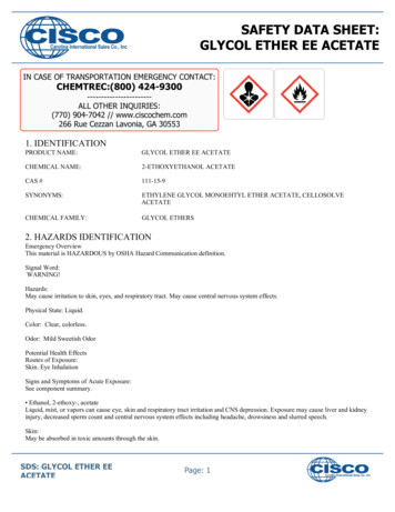
Chapter 2Background2.2 Cervical spine2.2.1 Anatomy of the spineThe human spine is divided into five regions as shown in Fig. 2.1. From cranialto caudal, the first seven (C1-C7) vertebrae constitute the cervical spine whichprovide neck flexibility and head movement (Kurtz & Edidin, 2006). The atlas(C1) and axis (C2) are very different to the rest of the cervical vertebrae; theyform a synovial joint rather than being separated by an intervertebral disc(McMinn et al., 1998). The first intervertebral disc locates between the C2 andC3 vertebral bodies, and is normally named according to its adjacentvertebrae.Each individual cervical vertebra comprises several essential structures (Fig.2.2). A flat slightly concaved vertebra body serves as the main load-bearingregion, thus spinal load can transmit along the vertebra column. Foramenformed by the lamina and pedicles provides a central pathway for the spinalcord. The orthogonally located spinous process and transverse processesprovide anchor points for muscle and soft tissue attachment. Articularprocesses lead to the formation of facet joints with adjacent vertebrae (McMinnet al., 1998; Louis-Ugbo et al., 2012). Facet joints are hinge-like synovial jointswhich control spinal motion and aid spinal column stability.7
Chapter 2BackgroundCervical regionC1 to C7Thoracic regionT1 to T12Lumbar regionL1 to L5SacrumCoccyxFig. 2.1: Anatomy structure of the spine (author’s own photograph, adaptedfrom Kurtz & Edidin, 2006).8
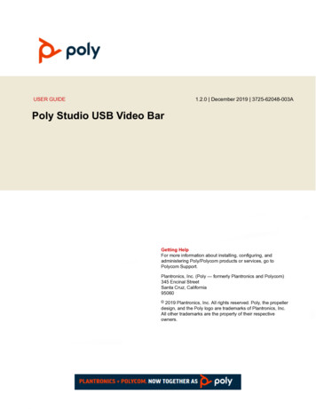
Chapter 2BackgroundFig. 2.2: The essential structure of a typical cervical vertebra (adapted fromLouis-Ugbo et al., 2012).2.2.2 Intervertebral discThe intervertebral disc is a fibrocartilagenous structure situated between eachof the rigid vertebrae (Roberts et al., 2006). It allows spinal motions andcontributes to the overall stability of the spinal column (Guerin & Elliott, 2006).Each disc includes several essential components as shown in Fig. 2.3. Aninner gelatinous nucleus pulposus is surrounded by an outer annulus fibrosus(i.e. fibrous ring). Two cartilaginous endplates are located at the superior andinferior of the intervertebral disc, and adjacent to the vertebrae. The shape andsize of the intervertebral discs vary along the spinal column. The cervical disc9
Chapter 2Backgroundis relatively small, with a round cross-section, which facilitates maximumflexibility of the neck. In contrast, the lumbar disc is optimised for structuralsupport, with a larger kidney-like cross-section (Kurtz & Edidin, 2006).The nucleus pulposus is composed of randomly distributed collagen fibrils in ahydrated extrafibrillar matrix. The main constituent is water which accounts for70-80% of its mass (Guerin & Elliott, 2006). Apart from water, collagens andproteoglycans contribute to most of its dry mass (Cassinelli et al., 2001; Guerin& Elliott, 2006). The predominated proteoglycans in the intervertebral disc ofmanyglycosaminoglycan (GAG) molecules and a core protein (Cassinelli et al.,2001). Since the GAG is negatively charged, it leads to the formation of anosmotic pressure within the nucleus pulposus. Water molecules are drawn intothe nucleus pulposus, and this process is called pressurization. The ability ofthe nucleus pulposus to pressurize is essential for efficiently absorbing andtransmitting axial loads through the spine (Guerin & Elliott, 2006; Pruitt &Chakravartula, 2011).10
Chapter 2BackgroundFig. 2.3: The essential components of intervertebral disc (Guerin & Elliott,2006).Apart from intervertebral disc, other soft tissues of the spine include ligamentsand the spinal cord which splits into the cauda equina at the lumbar vertebrae(Guerin & Elliott, 2006). Ligaments are connective tissues which tether thevertebrae together, aid stable spinal motion and prevent injury fromoverextension (Guerin & Elliott, 2006; Pruitt & Chakravartula, 2011). The spinalcord is a soft fragile neuron structure which conducts nerve impulse andactuates muscle contraction (Guerin & Elliott, 2006).11
Chapter 2Background2.2.3 Biomechanics of the cervical spine2.2.3.1 Anatomic coordinatesThe kinematic motions of the spine are normally described according to ananatomic reference frame (i.e. anatomic coordinates). In the anatomiccoordinates (Fig. 2.4), superior and inferior indicates the upward anddownward vertical directions, respectively. The front of the body is calledanterior, while the back of the body is termed posterior. The left and right sideof the body are the lateral sides and the medial direction is defined as towardsthe middle of the body (McMinn et al., 1998; Kurtz & Edidin, 2006).Fig. 2.4: Anatomic coordinate system (author’s own photographs, adaptedfrom Kurtz & Edidin, 2006).12
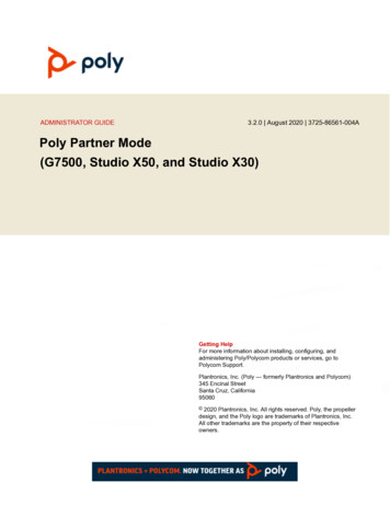
Chapter 2Background2.2.3.2 Motion of the cervical spineThe human spine offers a range of motions as shown in Fig. 2.5.Flexion-extension motion means the body bending in the anterior-posteriordirections, respectively. Sideways bending of the body is known as lateralbending and axial torsion refers to axial rotation (Kurtz & Edidin, 2006). In theC3-C7 region, the observed maximum ranges of angular motion are 10 , 11 and 7 for flexion-extension, lateral bending and axial rotation,respectively (Dvorak et al., 1992). A detailed description of the ranges ofmotion for each cervical spine segment is shown in Table 2.1.Fig. 2.5: The kinematic motions of the spine a) extension, b) flexion, c) lateralbend, and d) axial rotation.13
Chapter 2BackgroundTable 2.1: Range of motion (mean standard deviation) for each cervicalspine segment (Panjabi et al., 2001).DiscFlexion [ ]Extension [ ]SegmentLateral bendAxial rotation[ ][ ]C2-C33.5 1.32.7 1.09.6 1.83.3 0.8C3-C44.3 2.93.4 2.19.0 1.95.1 1.2C4-C55.3 3.04.8 1.99.3 1.76.8 1.3C5-C65.5 2.64.4 2.86.5 1.55.0 1.0C6-C73.7 2.13.4 1.95.4 1.52.9 0.82.2.3.3 Loading of the cervical spineThe loads acting on the cervical spine mainly arise from the weight of the head.Moreover, posture induced muscle contraction can result in additionalcompressive forces acting on the cervical spine (Cripton et al., 2006). Spinalloading can be determined experimentally via the measurement of intradiscalpressures (i.e. the hydrostatic pressure of the nucleus pulposus). Thistechnique is based on the fact tha
i ABSTRACT Poly-ether-ether-ketone (PEEK) is a high performance aromatic thermoplastic with proven biocompatibility. Recently, it has been proposed as a promising