Transcription
IntroductionThe following heat pump diagnostic flow charts and accompanying wiringdiagrams are to be used in diagnosing and repairing Hayward & Summit brandedpool heat pump systems. They are not intended for use with any othermanufacturers heat pumps.Summit Branded heat pumps are in Section 2 and have their own table ofcontents starting on page 32.However, there are certain portions of Section 1 that can be usedon all brands, and these are denoted by underlining them in the table of contentsHeat Pump pool heaters are similar to the heat pumps for home heating andcooling in that they contain refrigerant. As such, service personnel should observeEPA regulations for refrigerant handling. Pool heat pumps operate on 240 volts A/C.There is a risk of electric shock at all terminals and the heat pump should only beserviced by trained personnel.To use this guide, determine the model number of the heat pump and the natureof the problem.Refer to page one to find the appropriate page for the problem and followthe flow charts to the solution.If you have further questionsCall Hayward’s tech service department at 908-355-7995!High voltage. Danger! Useextreme caution. Do notattempt if you are not aqualified servicer.TCO models may have morethan one power source!
Table of ContentsProblem and Model Identification1Whats on the Display?223346778101010PSSH(SF)HI (HP)LPChecking a Thermostatic Expansion Valve(TXV) --All modelsOP (120) Blank DisplaydEFcOPcSHNon-Digital Display Diagnostics11HPABG/HP380 Diagnostics14Heat Pump Running But Not Heating-- All Models15Leaking Water-- All Models17Noisy-- All Models17Interface Board Connections183T & 4T Control Panel Parts Identification19Exploded Parts View20Thermistor Resistance v. Temperature26Wiring Diagrams27Heat Pump Data31Summit Heat Pump Table of Contents32
1What’s The Complaint?Unit not coming onRunning but not heatingRefer to page 15Runs for a few secondsand then shuts offLeaking waterRefer to page 17NoisyRefer to page 17What type of control for your heat pump?Model number is found on the dataplate located on the bottom right ofthe electrical cover on Hayward HeatPro units.On Summit style Heat Pumps thedata plate is located on the left sideof the base panDigital Display UnitsNon-Digital DisplayUnitsHPABG/HP380Diagnostics begin onpage 2Diagnostics Begin onPage 11Diagnostics Begin onPage 14
2What’s On The Display?Water flow issue. Heater requires aminimum flow of 30 GPM. The waterpressure switch is not sensing pressure. Isfilter pump on and filter clean? BypassPSSH(SF) HI(HP) Refer To Page 3LPRefer To Page 4OP(120)Refer To Page 7 closed?NOYESTurn on filterpump or cleanfilter.Refer To Page 7Blank Display Refer To Page 8NOdEFRefer To Page 10cOPRefer To Page 10cSHRefer To Page 10Check all connectionsat display board andwire harness.Connections OK?Check continuity(ohms reading)of pressure switch. Ohms readingzero? Fig A.Unit off & filter pump running.YESWith meter hooked up, adjustdial on switch counterclockwise until switch closesreading of zero Ohms. Fig ASwitch closed (zero Ohms)?YESYESCorrectconnections.Replace display boardand wire harnessDisconnect these wires andplace the test probe ends ateach terminal on the switch.NOUnit operates.NOReplace pressureswitch.Figure ARotate dial counterclockwise to check formis-adjustment. Switchwill ‘close’ and readingwill be zero Ohms.
3What’s On The Display?YESHI(HP)SH(SF)Does heat pump run fora short time, then cut offshowing Hi or HP?Is this a newinstall?NOYESNOIs this a newinstall?Check for loose wires tointerface board.Check for loose wires frominterface board to controlboard.YESNOSee Fig. BCheck Ohm’s reading on HP switch.Reading 0 Ohms?NOYESOn R-22 units abandonexisting switch.Replacement switch isa screw on switch. Useswivel tee on highside access port.Check all wires andconnections to interfaceboard and frominterface board todisplay board. Wiresand connections OK?See Fig. CFor Summit and4T Hayward modelsThe existing switch is a screw on,simply replace existing with new.Water Sensor failure.Check sensor withvalues in Chart 1.If values are not correct,replace sensor.Refer to chart, Page 24.Pg. 34 for Summit units.NOYESCorrect wiringReplace display andwiring harnessSee Note 1Note 1Heater runs for a while then shuts off and shows ‘HI orHP’ on display. Low water flow is normally the problem.Check filter and pump. A common problem whenrunning unit on spa only exists in the summer when spatemperature of about 100 F is reached and the unitshuts off with the ‘HI’ fault. At higher outdoor and watertemperatures a higher flow rate may be required forproper operation. The unit requires a minimum of 30GPM, but may require more under these conditions.On 3T and 4T heat pumps this can also be a sign of afailed TXV. Check capillary tube to TXV bulb for failure.See also Pg. 6Figure CFigure BInterface Board
4What’s On The Display?LPLow refrigerant pressure.YESDoes LP code flash constantly?See Page 5NODoes heater run for a few secondsand stop?NOSee Page 5YESDoes fan motor come on?Check fan capacitorSee note 9 on pg. 16check fan motor.NOYESAttach manifold gauges to heater.Start heater again. Does low sidepressure drop below 30 psi for R-22unit or80 psi on a R-410A unit?Figure C.NOReplace LP switch.See Note 2 belowYESCheck for refrigerant leak.Leak found?YESRepair leak and recharge.NOAdd 1 lb. of refrigerant. Doesthis make a difference inoperating pressure?NOCheck expansion valve.See page 6YESThere has been a lossof charge.Re-check for leaks,recharge and test.Figure CNote 2Abandon existing switch on HaywardR-22 units. Replacement switch is ascrew on switch. Use a swivel tee onthe low side access port.On Summit and R-410A (4T)Hayward units the existing switch isscrew on.Replace existing with new.Low side charging port
5What’s On The Display?Attach low side (blue) manifold gaugehose to heat pump.LPSee Figure ENOIs pressure reading 65 psi for R-22 units?YESor 120 psi for R-410A units?See note 3 belowPerform leak check on heatpump. Leak found?Some refrigerant may need tobe added if unit is completelyemptyCheck Ohm’s (continuity) reading onLP switch. Reading zero Ohm’s?YESRepair and rechargeas needed.See Fig. DNOReplace LPswitch.NOSee Note 4Fig. E belowRemove tube to water pressure switchfrom top of exchanger and check forrefrigerant in the water. Refrigerantdetected in water?YESCheck all wires andconnections to interfaceboard and from interfaceboard to display board. Wiresand connections OK?YESReplace display boardand wire harnessYESNOCorrect wiresor connectionsUnit breached.Replace unit.Figure DFigure ENOTE 3If water comes out of access portwhen removing gauge hose, unit isbreached and will have to bereplaced.NOTE 4Abandon existing switch forHayward R-22 heat pumps.Replacement switch is a screw onswitch. Use a swivel tee on the lowside access port.For Summit and Hayward R-410Aunits replace existing screw on LPswitch with new.Low sideHigh sidemarked witha red tagBlue LP wires. Remove and connect multimeterto wire ends and measure Ohm’s reading. Setscale on meter to lowest setting.
6Checking Expansion Valve (TXV)Note:On 3T and 4T heat pumpsfailure mode for a failed TXV is normallyHI error code. Check water flow, and valvepositions to rule out other possible reasonsfor HI code. Check capillary to bulb forbreakage. Be sure heat pump is actuallyfailing on High Pressure by attaching gaugesto service ports. If so replace TXV.After adding 1 lb. Refrigerant toSystem, there is little orno difference in operatingpressuresCheck capillary tube from TXV headto bulb attached to suction line nearleft edge of evaporator coil.Capillary tube broken or cracked?YESReplace TXVSee Note BelowNO3T ModelsSensor bulbCapillary tubeRemove cap from bottom of TXVusing 5/8” wrench, and attach 3/16” valvewrench to adjusting stem of TXV.Turn valveclockwise until closed,then turn valvecounter-clockwise until completely open,then turn valve clockwise until closed again.Now open valve number of turns listed bymodel in Table1 below. Restart heat pump.Heat pump runs normally?YESHeat pump runsNOReplace TXVTXVNoteOn Hayward units only heat pumps with3T in model number have adjustable TXV.All Summit R-22 heat pumps have adjustable TXVFor all other models replace TXV if no differenceIn operating pressures after adding refrigerant.Table 1Adjust TXV with valve wrenchHP6003T2.5 turnsHP21003T3.5 turnsHP21203T1.75 turnsSummit TXV settingscan be found on page 33.Remove cap
7What’s On The Display?Water sensor failure. Testsensor against resistancewater temperature chart onpage 24. See Fig. FOP(120)Replace sensorSee Figure GNOReadings OK?YESYESCheck all wires andconnections to interfaceboard and from interfaceboard to display board.Wires and connections OK? Heater is in standby mode.Press Pool or Spa to energize.Does unit energize?OKNOReplace display board.NOReplace display boardand wire harnessCorrect wires orconnectionsFigure GFigure FSensor is located in water inlet pipeTo replace loosen band clamp andpull sensor out of tube.NoteRemove top two wires. Test Ohm’sreading by hooking meter leads, oneto each wire. Refer to chart on page26 for correct reading.In some older model heat pumpstemp. sensor is located in wellon left side of heat exchanger base.
8What’s On The Display?Blank display, unit notrunning.TCO model?YESNORemove front panel. Checkvoltage between contactor L1 &L2. Voltage 240volts?See Fig. HYESRemove front panel. Is powerconnected to compressor (heater)contactor? See Fig. JNONOYESTurn off power to heater!Check circuit breaker at main.Check for short to ground, T1 toground & T2 to ground. Short toground found?See page 8Correct wiringSee Fig. J!See Figure H & Note 7High voltage. Danger!YESCheck fan andcompressor to ground.Replace as needed. Ifcompressor is shortedcontact Tech Support908 355-7995Note 7NOMain power feedproblemTo check for grounded unit (short), turn off power to heater. Setmulti-meter to zero Ohm’s. Place one test lead on T1 and thenT2 and the other test lead to grounding lug in panel.(Figure H)Any reading of continuity indicates a grounded component.Disconnect all wires to fan and check each one to ground lug. Areading of continuity means a bad fan motor. Check thecompressor the same way. Be sure all wires for eachcomponent are disconnected before testing.Figure JFigure HCheck both T1 & T2to ground lug in panelfor short.Check across L1 &L2 for 240 volts.On TCO control panel. Leftcontactor set is heatercontactor.
From page 89What’s On The Display?Blank display240 volts betweenL1 & L2?YESCheck for 24 volts betweenterminals 1 & 2 on theinterface board. 24 volts?NOCheck for 24 volts AC betweenblue and yellow wires fromtransformer. 24 volts?See Fig. LSee Fig. LYESYESReplace display boardReplace interface boardYESCheck for blown fuse oninterface board. Fusegood?NOCheck low voltage wiresFor shorts or grounds.Then replace transformerSee Fig. MNOCheck all low voltage wires, and safety switches, for shorts or groundsReplace fuse.Figure LFigure M!High voltage.Danger!Replace only with 1 ampfuseCheck for 24 volts at terminals 1 & 2.Remove bottom two leads(yellow and blue) and check for24 volts AC
10What’s On The Display?Heat pump is in Defrost ModeAfter 2 hours the heat pump willautomatically resumenormal operation.(See note 1 below)dEFcOPCoil Sensor errorcSHHeat pump resumesnormal operation after2 hours?Replace sensorNOCheck coil temperature sensorusing chart on page 16.Sensor reading correctly?NOYESHeat PumpworkingYESCorrectWiringCheck wiring to sensor.And wiring harnessNOfrom interface tocontrol board.Wiring OK?Coil sensor connection at interface boardYESReplace control boardNOTE 1Defrost operation of heat pumps (3T and 4T Models)When the coil temperature sensor senses that the coil temp. is low enough thatfrost will start to form on the coil,it will cut the compressor off and continue to runthe fan for 15 minutes. After 15 minutes it will check the coil temp. again.If the temperature has reached operating temperature the heat pump will resumenormal operation. If it hasn’t, the heat pump will continue to run the fan with thecompressor off for an additional 15 minutes before checking the coil temperature again.The heat pump will go thru a 3rd fan only cycle, and if the temperature is still notsufficient for safe, normal operation, the heat pump will shut down and display dEF.The heat pump will be off for 2 hours, and then will begin the defrost process asdescribed above, again.
What’s the problem?11Non-Digital display modelsYESIs power light on?With pump running and thermostatturned to max, check voltage betweenterminal 1 on TB1 and the blue wire ontime delay relay. 24 volts?See figs. O & QNon-Digital DisplayModelsNONOCheck voltage atcontactor L1 & L2.240 volts?NOYESNOReplace transformerYESCheck voltage acrossconnectors on blue andyellow wires leading fromtransformer. 24 volts?Replace power light.Return to power light ondiagnostic if neededafter light replacementSee Fig. RCheck voltage acrossblack/red wire and yellow wireon contactor. 24 volts?See Fig. PRefer to diagnosticsbeginning on page 7YESGo to page 12NOReplace time delay relayYES!Replace contactorHigh voltage. Danger!Figure PFigure QFigure OCheck for 24 voltsbetween terminal 1 onTB1 & blue wire ontime delay relayCheck for 24 volts acrossblack/red & yellow wireCheck for 24 volts across bluewire and terminal 1 on TB1Figure R
12From page 11Unit will not run. 24 volts presentat transformerSafety switch open. Attachmanifold gauge hoses and checkNOlow side pressure.Pressure 80 psi?Non-Digital DisplayModels!Out of refrigerant.Repair leak andrecharge.See Fig. RHigh voltage. Danger!See note 4NOTE 4YESIf water comes out of access portwhen removing gauge hose, unit isbreached and will have to bereplaced.Turn power off to heaterWith filter pump runningCheck continuity(ohms reading)of pressure switch. Ohmsreading zero?YESFig A. Unit off & filter pump running.Check continuity of LP and HPswitches.Check between black wire on waterpressure switch and blue wire ontime delay relay. If no continuity,isolate switches and checkindividually. Ohms Reading zero?NOReplace switchwith no continuityNOTEFig. A Switch closed (zero Ohms)?Unit operates.Abandon existing switch.Replacement switch is a screw onswitch. Use a swivel tee on therefrigerant access port.NOReplacepressure switch.Figure RDisconnect thesewires and place thetest probe ends ateach terminal onthe switch.Low side portGo topage 13NOWith meter hooked up, adjustdial on switch counterclockwise until switch closesreading of zero Ohms.YESYESFigure ARotate dial counterclockwise to check formis-adjustment. Switchwill ‘close’ and readingwill be zero Ohms.
From page 121324 volts at transformer.Non-Digital DisplayModels0 ohms resistance through safety switchesCheck sensor values against Chart 1on page 24. Value correct?NOReplace sensorSee Fig. V & Note 17YESCheck potentiometer on face plate.See Note 16 & Fig. TOhm’s reading correct?NOReplace faceplateYESReplace control boardNote 16Disconnect harness from faceplate. Attachmeter leads to the two large wires leadingfrom the control. Resistance should be from0 Ohm’s at off to 13 Ohm’s at full on.Figure TNote 17Disconnect leads to sensor. Attach meterleads to each lead of sensor. Comparereading to Chart 1 on page 24.Figure V
14Service Provider DiagnosticFor HPABG/HP380YESIs power light on?NOAttach manifold gauge hoses.Low side 65 psi?Check voltage at L1& L2. 240 volts?See Note 20See Note 20YESNOBad indicator light. ReplaceRefrigerant low. Leak checkand repair.YESNONOCheck voltage between L1 andyellow lead on time delay relay.240 volts?Unit operating?Is heat light on?YESYESNOReplace contactorYESCheck voltage from L1to orange lead on timedelay relay. 240 volts?Replace timedelay relayNOUnit has been wires with110 volts. InstallationerrorNOProblem with mainpower. Check heater forgrounded componentsusing diagnostic onpage 7.Check voltage from L1 to orangelead on water pressure switch.240 volts?YESReplace thermostatNOTurn off power to heaterMeasure Ohm’s reading on lowpressure switch.Ohm’s reading 0?NOYESNote 20Remove thermostat knob and remove frontpanel.!High voltage. Danger!Replace low pressureswitchReplace high pressureswitchMeasure Ohm’s reading on highpressure switch.Ohm’s reading 0?NO
15What’s the Problem?Running but not heatingIs air coming out of top of unit (blowingfrom fan) colder than the ambient(outside) air?NOCheck unit for compressor operation by connectingmanifold gauge hoses to service ports. If thecompressor is running, the low side pressure willbe considerably lower than the high side pressure.The high side pressure will vary depending on thewater temperature and the water flow rate. If thecompressor is not operating, both pressures will bethe same.YESThe difference in air temperature should bearound 12 to 16 degrees, less in lowerhumidity conditions, 6 to 8 degrees. If this isthe case, the unit is operating correctly. Theproblem could be too short a run time. Adjustas necessary. It may also be necessary to adda solar cover to prevent evaporative cooling ofthe water.YESLow side pressure considerably lower thanhigh side pressure?NOTURN OFF POWER TO UNIT!Check for burned wires oncompressor, capacitor andcontactor. Wires OK?YES!High voltage. Danger!NOCheck compressorcapacitor. Capacitor OK?Replace wiresSee Fig. N and Note 9page 16NOYESGo to page 16Replace capacitorCheck compressor for internaloverload trip.
16From Page 15Remove wires from compressor to capacitor and contactor.Set meter to lowest Ohm setting. Check reading betweenthe red and blue wires. Reading of infinite resistance?NOCompressor may be stuck.Install hard start capacitorbetween terminalson compressor capacitorand retry.Fig. OYESIf compressor doesn’t startContact Tech Support908-355-7995For further instructionOverload on compressor may be open. It must coolbefore it will reset. To verify, check resistance betweenblack and blue wires. If resistance here is infinite, checkbetween red and black. The resistance here should beless than 3 Ohms. If it is, the overload is open. Oncereset it will attempt to operate again.Figure NCapacitorsNote 9Checking a capacitorDisconnect capacitor wires. With meter set at 20k Ohmscale, place test leads on terminals. The resistanceshould initially be high, then slowly drop towards zero.This will happen very quickly when checking a fancapacitor, and will take several seconds when checkinga compressor capacitor. This indicates a goodcapacitor. If you have a reading of no resistance, (0.00on your read-out) or if the capacitor does not cause themeter to “jump up “ to a high resistance then fall back,the capacitor is bad. If you have a capacitance settingon your meter, place the test leads across the terminals.You should see a reading of between 6 and 8microfarads.for a fan capacitor, and 60 to 80 for acompressor capacitor.Note 10Hard start kit installson compressorcapacitor terminalsCompressorFigure OFanNoteOlder modelshave 1 dual capacitornot individual fan &compressor capacitors.Check is the same
17What’s the problem?LEAKING WATERIs unit leaking when notrunning?NOISYYESNOWater around unit while runningis normal condensation. Unitcan produce as much as 3-5gallons of water an hour,depending on conditions.Check water around unit with achlorine test strip.Condensation will not havechlorine. Alternately, shut unitoff and allow system pump tooperate for 12 hours. If waterdries up, it is condensation.Common noises and problemsGrindingFan motorScreechingFan motorChatteringBuzzingBad wiring or controlboard.Contactor See Note13Check condenser for water leaks.See Note 12Note 13Note 12Cracked condensers are usually caused by freezedamage. Freeze damage is not covered under warranty.A buzzing contactor will normally clear itselfup in a few days. The problem is usuallymore common in the spring and fall when theunit is being used after being shut down forseveral weeks.
18Interface Board ConnectionsLow voltageGroundWater tempSensorRefrigerantTemp. SensorOnly on 3T & 4TmodelsTCOContactorFanContactoron 3T & 4T modelsReversingValve (HP3100)CompressorContactorWater PressureSwitchLow PressureSwitchHigh PressureSwitchNot ns
19Control Panel PartsIdentification3T and 4T Models11. Interface Board2. Transformer3. Water Pressure Switch4. Compressor Capacitor5. Fan Motor Capacitor6. Compressor Contactor7. Fan Motor Contactor8. TCO Contactor (if used)2345TCO Contactor not shown678
167158179110241154181219201322361422120
21HAYWARD HEAT PRO 4T PARTS 6272829Part descriptionFAN TOPSIDE PANELCONTROL BOX COVERCONTROL BOXCONTACTORCONTROL BOARD ASSYINTERFACE BOARDWATER PRESSURE SWITCHTRANSFORMERCAPACITORBENT COIL with GUARDCOMPRESSORCONDENSERCOVER GASKETFAN MOTOR, 1/3 HPFAN GUARDFAN BLADEREPLACEMENT HP SWITCHREPLACEMENT LP SWITCHEXPANSION VALVE ASSYTEMPERATURE SENSORELECTRICAL ENTRY PLUGFAN RUN CAPACITORDEFROST SENSOR (NS)HPC CABLE (NS)COMPRESSOR MOUNT KIT (NS)COMPRESSOR EL. PLUG (NS)REPLACEMENT FILTER DRIERUNION KITHP211404T (builton Summit 4210HPX15024214HP20854BT(Canada only)HP20654THP20654BT(Canada only)HPX01024821HPX01023502 HPX01024821HPX01024822HPX01023503 24289HPX10024732HPX1462SPX3200UNKIT
Parts Breakdown (3T Models)22
23Parts Breakdown (3T Models)ItemPart descriptionHP21203THP21003THP2100TCO3T1FAN TOPHPX010235022SIDE PANELHPX010235033CONTROL BOX COVERHPX010235044CONTROL BOXHPX010235055CONTACTOR6CONTROL BOARD ASSY7INTERFACE BOARD8WATER PRESSURE 11BENT COIL with GUARD12COMPRESSOR13CONDENSERHPX2402394114COVER GASKETHPX0502354915HPC CABLE (NS)HPX1002351716FAN MOTOR, 1/3 HPHPX1102356417FAN GUARDHPX0102356118COMPRESSOR BLANKET X11024170HPX11024077HPX02024108--20FAN BLADE21REPLACEMENT HP SWITCHHPX218622REPLACEMENT LP SWITCHHPX217923EXPANSION VALVE 24026HPX15024023-25TEMPERATURE SENSOR26SCREW REPLACEMENT KIT (NS)HPXSCRKIT127COMPRESSOR MOUNT KIT (NS)HPX005428COMPRESSOR EL. PLUG (NS)HPX222329ELECTRICAL ENTRY PLUG30DRAIN PLUG31FAN RUN CAPACITORHPX1102415132DEFROST SENSORHPX11024169HPX2169HPX01023760SPX4000FG
24Parts Breakdown Generation 2 Models
25Parts Breakdown HPABG / HP380 models
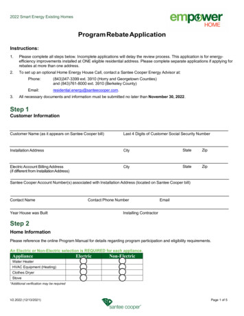
26Thermistor Resistance vs Temp.CHART 1110100908070Temp F605040302010504540353025201510Ohms x 1000Example: Outside ambient temperature is 80 F. Locate this on left hand side ofchart and move across to the right until you meet the graph line intersection. Atthe intersection, move down the chart and locate the respective Ohm’s reading.For an outside temperature of 80 F, the respective Ohm’s reading is 9 (times1000) 9,000 Ohm’s. If the sensor reading does not match this, replace sensor.5
273T & 4T Models Wiring Diagram(except HP2100TCO3T)HP2100TCO3T Wiring Diagram
Wiring Diagram for Digital Control Heat PumpsExcept 3T ModelsConnection of remote controllers to Digital Control Heat PumpsFor 2 wire remote controllers such as the Goldline AquaLogic, connect to terminals 1 & 2 on theinterface board(labeled remote heat).For 3 wire remote controllers, where the heat pump retains temperature control, connect yourcommon wire to terminal # 4, pool wire to terminal #3 and spa to terminal # 5.The heat pump must be in the standby mode for the remote to control the unit.For 2 wire air switch controls (popular in Florida) where the heat pump is controlling the temp. useterminals 3 and 4.28
29Wiring diagram for Non-Digital Control Heat PumpsConnection of Remote Controllers for Non-Digital ModelsThe mechanical control heat pumps are compatible with 2 wire remotes such asthe Goldline AquaLogic. To connect the remote, remove the jumper betweenterminals 1 & 2 on terminal block 1(TB1) and replace it with the 2 wires from yourremote. Turn the thermostat all the way up on the heat pump. These units are notcompatible with 3 wire remotes.For 2 wire air switch installations remove the jumper between terminals 1 & 2and replace it with the 2 wires from your switch. Set the thermostat on the heatpump to the desired temp.
30Wiring Diagram HPABG / HP380
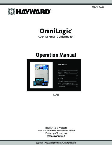
31Hayward Heat Pump DataDescriptionGeneration 1Generation 2Model 2Refrigerant TypeR-22R-22R-22R-22R-22R-22Factory Charge10 lbs.5 lbs. 10 oz5 lbs. 10 oz5 lbs. 10 oz5 lbs. 10 oz6 lbs.Factory Test Pressure300 psi300 psi300 psi300 psi300 psi300 psiCompressor Amps27.927.927.927.927.918.2Compressor LRA129129129129129115Fan Amps1.81.81.81.81.81.8Fan LRA2.82.82.82.82.82.8Minimum Water Flow30 gpm30 gpm.30 gpm30 gpm30 gpm30 gpmMaximum Water Flow75 gpm75 gpm75 gpm75 gpm75 gpm75 gpmMaximum Water Inlet Temp.108 F108 F108 F108 F108 F108 FNominal Power Required (Watts)615061506150615061504200A/C Power230v 60Hz 1Ph 230v 60 Hz 1Ph 230v 60Hz 1Ph 230v 60 Hz 1Ph 230v 60Hz 1Ph 230v 60 Hz 1PhMax. Circuit Breaker505050505040Min. Circuit Ampacity404040404030DescriptionGeneration 3Model frigerant TypeR-22R-22R-22R-22R-22Factory Charge4 lb 12 oz4 lb 4 oz4 lb 4 oz4 lb 4 oz3 lb 14 ozFactory Test Pressure300 psi300 psi300 psi300 psi300 psiCompressor Amps33.528282818.2Compressor LRA176176176176137Fan Amps1.81.81.81.81.8Fan LRA2.82.82.82.82.8Minimum Water Flow30 gpm30 gpm30 gpm30 gpm30 gpmMaximum Water Flow75 gpm75 gpm75 gpm75 gpm75 gpmMaximum Water Inlet Temp.108 F108 F108 F108 F108 FNominal Power Required (Watts)73006200620062004200A/C Power230v 60Hz 1Ph 230v 60Hz 1Ph 230v 60Hz 1Ph 230v 60Hz 1Ph 230v 60Hz 1PhMax. Circuit Breaker6050505040Min. Circuit Ampacity6040404030DescriptionGeneration 4Model igerant TypeR-410AR-410AR-410AR-410AR-410AFactory Charge3 lbs. 0 oz.3 lbs. 14 oz.4 lbs. 2 oz5 lbs. 6 oz. 5 LBS. 13.5 OZ.Factory Test Pressure440 psig441 psig441 psig441 psig441 psigCompressor Amps10.517.9282727Compressor LRA60112135145145Fan Amps1.31.81.81.82.4Fan LRA2.82.82.82.84.3Minimum Water Flow3030303030Maximum Water Flow7575757575Maximum Water Inlet Temp.108108108108108Nominal Power Required (Watts)24002830370054006600A/C Power230v 60Hz 1Ph 230v 60Hz 1Ph 230v 60Hz 1Ph 230v 60Hz 1Ph 230v 60Hz 1PhMax. Circuit Breaker2040606060Min. Circuit Ampacity14.424363536.2* HP50TA, AND HP21404T ARE BUILT ON SUMMIT PLATFORM. LOOK TO SUMMIT EXPLODED VIEW FORPARTS DESCRIPTION AND LOCATION.
32SUMMIT HEAT PUMP TECHNICAL SERVICE GUIDETABLE OF CONTENTSDEFROST OPERATION33HEAT EXCHANGER/CONDENSER REPLACEMENT33TXV'S & ADJUSTMENT34TEMPERATURE SENSORS35ERROR CODES/MEANINGS/CAUSES/SOLUTIONS36 - 40BLANK DISPLAY36REMOTE CONNECTIONS40 - 41REPLACING OLD STYLE CONTROL BOARD WITH NEW42WIRING DIAGRAMS43 - 44EXPLODED VIEW45PARTS LIST46 - 47SUMMIT HEAT PUMP DATA48
33Summit Heat Pump Tech Service GuideDefrost OperationHeat pump will operate normally until evaporator coil sensor senses anevaporator coil temperature of 24º F. At this point the control will turn thecompressor off, display FS, and leave the fan running until the evaporator coiltemperature rises to 42º F. Once 42º is reached the heat pump will turn thecompressor back on and the heat pump will run normally. There is no time limiton the defrost cycle, it will run in this cycle as long as necessary for the heatpump to warm up to 42º.Fan Motor ReplacementAll Summit fan motors come with female spade connectors that mate with malespade connectors just inside the electrical box. Do not cut wires.Heat Exchanger/Condenser ReplacementYou have to cut the female unionconnectors off existing heat exchangers toremove/ replace them. New heatexchanger will come with new female unionends, and nipples to attach. Do not attacheither the nipple or the union until the heatexchanger has been installed into heater.Heat exchanger will not set in heat pumpwith nipples attached. See picture abovefor technique to cut unions using wire saw.TO REPLACE HEAT EXCHANGER/CONDENSER1. Cut water lines outside unit (see picture above)2. Cut liquid and hot gas lines in a convenient place to reconnect later.3. Cut tie-wrap on front of condenser4. Lift condenser out of heat pump5. Install new condenser6. Cut hot gas and liquid lines attached to new condenser to match linesfrom unit and braze in.7. Glue in nipples and male union section that come separate fromcondenser
34TXVAll TXV’s on R-22 Summit units are adjustable type. TXV’s on R-410A unitsare not.Refrigerant charges are on chart Pg. 44Do not attempt to calibrate TXV unless you have been authorized to do so byHayward/Summit tech service. Once you have been authorized use the followingprocedure.1. Remove cap from rear of TXV assembly being sure to use back upwrench on valve body.2. Using valve wrench turn adjusting stem clockwise until fully closed (do notover tighten).3. Then open valve fully open4. Adjust valve to setting listed in table HCB125BTHEATMASTERHML80THML110THML125TOASIS56VALVE SETTINGclosed 5 turns from totally openclosed 5 turns from totally openclosed 7 3/4 turns from totally openclosed 9 1/2 turns from totally openclosed 5 turns from t
The following heat pump diagnostic flow charts and accompanying wiring diagrams are to be used in diagnosing and repairing Hayward & Summit branded pool heat pump systems. They are not intended for use with any other manufacturers heat pumps. Summit Branded heat pumps are in Section 2 and have their own table of contents starting on page 32.