Transcription
SWIMMING POOL HEAT PUMP UNITInstallation & Instruction ManualPart T/32P26T/32Automated Environmental Systems Ltd.Unit 1, 1 Wimbledon Avenue, Brandon, Suffolk, IP27 0NZ01842 819130 sales@automatedenvironmentalsystems.co.uk
CONTENTS1. Preface12. Specifications42.1 Performance Data of Swimming Pool Heat Pump Unit42.2 Dimensions for Swimming Pool Heat Pump Unit83. Installation and Connection93.1 Installation illustration93.2 Swimming Pool Heat Pumps Location113.3 How Close to Your Pool?113.4 Swimming Pool Heat Pumps Plumbing123.5 Swimming Pool Heat Pumps Electrical Wiring133.6 Initial Start-up of the Unit134. Use and Operation Instruction of Wire Controller144.1 Function of controller144.2 The controller usage164.3 Parameter table234.4 Connection of PCB illustration245. Maintenance and Inspectio256.Appendix316.1 Circuit diagram316.2 Cable specification346.3 Comparison table of refrigerant saturation temperature35
1. PREFACEIn order to provide our customers with quality, reliability and versatility, this product hasbeen made to strict production standards. This manual includes all the necessaryinformation about installation, debugging, discharging and maintenance. Please read thismanual carefully before you open or maintain the unit. The manufacture of this product willnot be held responsible if someone is injured or the unit is damaged, as a result ofimproper installation, debugging, or unnecessary maintenance. It is vital that theinstructions within this manual are adhered to at all times. The unit must be installed byqualified personnel.The unit can only be repaired by qualified installer centre , personnel or an authoriseddealer.Maintenance and operation must be carried out according to the recomended time andfrequency, as stated in this manual.Use genuine standard spare parts only.Failure to comply with these recommendations will invalidate the warranty.Swimming Pool Heat Pump Unit heats the swimming pool water and keeps the temperatureconstant. For split type unit, The indoor unit can be Discretely hidden or semi-hidden tosuit a luxury house.Our heat pump has following characteristics:1 DurableThe heat exchanger is made of PVC & Titanium tube which can withstand prolongedexposure to swimming pool water.2 Installation flexibilityThe unit can be installed outdoors or indoors.3 Quiet operationThe unit comprises an efficient rotary/ scroll compressor and a low-noise fan motor,which guarantees its quiet operation.4 Advanced controllingThe unit includes micro-computer controlling, allowing all operation parameters to beset. Operation status can be displayed on the LCD wire controller. Remote controller can bechosen as future option.WARNINGIt is recommended that your pool filtration pump and your heat pump are wiredindependently. Wiring your pool pump into the heat pump will result in yourfiltration being switched off once the pool water has reached temperature. Onlywire the pool pump through the heat pump if you have a pool pump for heatingonly that is independent to your pool filtration system.Do not use means to accelerate the defrosting process or to clean,Other than those recimmended by the manufacturer.The appliance shall be stored in a room without continuously operating ignition sources (forexample:open flames, an operating gas appliance or an operating electric heater.)Do not pierce or burn.Be aware that refrigerants may not contain an odour,Appliance shall be installed,operated and stored in a room with a floor area larger than 30 .NOTE The manufacturer may provide other suitable examples or may provide additionalinformation about the refrigerant odour.1
1. PREFACEThis appliance can be used by children aged from 8 years and above and persons withreduced physical, sensory or mental capabilities or lack of experience and knowledge ifthey have been given supervision or instruction concerning use of the appliance in a safeway and understand the hazards involved. Children shall not play with the appliance.Cleaning and user maintenance shall not be made by children without supervision.If the supply cord is damaged, it must be replaced by the manufacturer, its service agent orsimilarly qualified persons in order to avoid a hazard.The appliance shall be installed in accordance with national wiring regulations.Do not operate your air conditioner in a wet room such as a bathroom or laundry room.Before obtaining access to terminals, all supply circuits must be disconnected.An all-pole disconnection device which has at least 3mm clearances in all poleV , DQG have aleakage current that may exceed 10mA, WKH residual current device (RCD) having a rated residualoperating current not exceeding 30mA, DQG disconnection must be incorporated in the fixed wiringin accordance with the wiring rules.Do not use means to accelerate the defrosting process or to clean, other than thoserecommended by the manufacturerThe appliance shall be stored in a room without continuously operating ignition sources (forexample: open flames, an operating gas appliance or an operating electric heater.)Do not pierce or burnAppliance shall be installed, operated and stored in a room with a floor area larger than 30 m2Be aware that refrigerants may not contain an odour.The installation of pipe-work shall be kept to a minimum 30 m 2Spaces where refrigerant pipes shall be compliance with national gas regulations.Servicing shall be performed only as recommended by the manufacturer.The appliance shall be stored in a well-ventilated area where the room size corresponds to theroom area as specified for operation.All working procedure that affets safety means shall only be carried by competent persons.Transport of equipment containing flammable refrigerantsCompliance with the transport regulationsMarking of equipment using signsCompliance with local regulationsDisposal of equipment using flammable refrigerantsCompliance with national regulationsStorage of equipment/appliancesThe storage of equipment should be in accordance with the manufacturer's instructions.Storage of packed (unsold) equipmentStorage package protection should be constructed such that mechanical damage to theequipment inside the package will not cause a leak of the refrigerant charge.The maximum number of pieces of equipment permitted to be stored together will bedetermined by local regulations.2
1. PREFACECaution & Warning1. The unit can only be repaired by qualified installer centre personnel or an authoriseddealer.(for Europe market)2. This appliance is not intended for use by persons (including children) with reduced physicalsensory or mental capabilities, or lack of experience and knowledge, unless they have beengiven supervision or instruction concerning use of the appliance by a person responsible fortheir safety. (for Europe market)Children should be supervised to ensure that they do not play with the appliance.3. Please make sure that the unit and power connection have good earthing, otherwise maycause electrical shock.4. If the supply cord is damaged, it must be replaced by the manufacturer or our service agentor similarly qualified person in order to avoid a hazard.5. Directive 2002/96/EC (WEEE):The symbol depicting a crossed-out waste bin that is underneath the appliance indicates thatthis product, at the end of its useful life, must be handled separately from domestic waste,must be taken to a recycling centre for electric and electronic devices or handed back to thedealer when purchasing an equivalent appliance.6. Directive 2002/95/EC (RoHs): This product is compliant with directive 2002/95/EC (RoHs)concerning restrictions for the use of harmful substances in electric and electronic devices.7. The unit CANNOT be installed near the flammable gas. Once there is any leakage of the gas, fire can be occur.8. Make sure that there is circuit breaker for the unit, lack of circuit breaker can lead toelectrical shock or fire.9. The heat pump located inside the unit is equipped with an over-load protection system. Itdoes not allow for the unit to start for at least 3 minutes from a previous stoppage.10.The unit can only be repaired by the qualified personnel of an installer center or anauthorized dealer. (for North America market)11. Installation must be performed in accordance with the NEC/CEC by authorized person only.(for North America market)12. USE SUPPLY WIRES SUITABLE FOR 75 .13. Caution: Single wall heat exchanger, not suitable for potable water connection.3
2.SPECIFICATION2.1 Performance data of Swimming Pool Heat Pump Unit*** REFRIGERANT : R32UNITPart nr.Heating capacity(A27/W26)Heating Power InputCOPHeating capacity(A15/W26)Heating Power InputCOPPower SupplyCompressor QuantityCompressorFan NumberFan Power InputFan Rotate SpeedFan DirectionNoiseWater ConnectionWater Flow VolumeWater Pressure Drop(max)Unit Net Dimensions(L/W/H)Unit Ship Dimensions(L/W/H)Net WeightShipping WeightkWBtu/hkWkWBtu/hkWWRPMdB(A)mm3m 54.33220-240V /50Hz220-240V l505250502.33.02.43.2See the drawing of the unitsSee package lablesee nameplatesee package labelHeating: Outdoor air temp: 27 /24.3 , Inlet water temp:26 Outdoor air temp: 15 /12 , Inlet water temp:26 Operating range:Ambient temperature:-7—43 Water temperature:9-40 4
2.SPECIFICATION2.1 Performance data of Swimming Pool Heat Pump Unit*** REFRIGERANT : R32UNITPart nr.Heating capacity(A27/W26)Heating Power InputCOPHeating capacity(A15/W26)Heating Power InputCOPPower SupplyCompressor QuantityCompressorFan NumberFan Power InputFan Rotate SpeedFan DirectionNoiseWater ConnectionWater Flow VolumeWater Pressure Drop(max)Unit Net Dimensions(L/W/H)Unit Ship Dimensions(L/W/H)Net WeightShipping WeightkWBtu/hkWkWBtu/hkWWRPMdB(A)mm3m 4.52220-240V /50Hz220-240V l545450504.55.33.510See the drawing of the unitsSee package lablesee nameplatesee package labelHeating: Outdoor air temp: 27 /24.3 , Inlet water temp:26 Outdoor air temp: 15 /12 , Inlet water temp:26 Operating range:Ambient temperature:-7—43 Water temperature:9-40 5
2.SPECIFICATION2.1 Performance data of Swimming Pool Heat Pump Unit*** REFRIGERANT : R32UNITPart nr.Heating capacity(A27/W26)Heating Power InputCOPHeating capacity(A15/W26)Heating Power InputCOPPower SupplyCompressor QuantityCompressorFan NumberFan Power InputFan Rotate SpeedFan DirectionNoiseWater ConnectionWater Flow VolumeWater Pressure Drop(max)Unit Net Dimensions(L/W/H)Unit Ship Dimensions(L/W/H)Net WeightShipping WeightkWBtu/hkWkWBtu/hkWWRPMdB(A)mm3m 15.06220-240V /50Hz220-240V ntal545850506.87.52028See the drawing of the unitsSee package lablesee nameplatesee package labelHeating: Outdoor air temp: 27 /24.3 , Inlet water temp:26 Outdoor air temp: 15 /12 , Inlet water temp:26 Operating range:Ambient temperature:-7—43 Water temperature:9-40 6
2.SPECIFICATION2.1 Performance data of Swimming Pool Heat Pump Unit*** REFRIGERANT : R32UNITPart nr.Heating capacity(A27/W26)Heating Power InputCOPHeating capacity(A15/W26)Heating Power InputCOPPower SupplyCompressor QuantityCompressorFan NumberFan Power InputFan Rotate SpeedFan DirectionNoiseWater ConnectionWater Flow VolumeWater Pressure Drop(max)Unit Net Dimensions(L/W/H)Unit Ship Dimensions(L/W/H)Net WeightShipping WeightkWBtu/hkWkWBtu/hkWWRPMdB(A)mm3m 55.065.09380-400V/3N /50Hz380-400V/3N izntal585850507.59.02828See the drawing of the unitsSee package lablesee nameplatesee package labelHeating: Outdoor air temp: 27 /24.3 , Inlet water temp:26 Outdoor air temp: 15 /12 , Inlet water temp:26 Operating range:Ambient temperature:-7—43 Water temperature:9-40 7
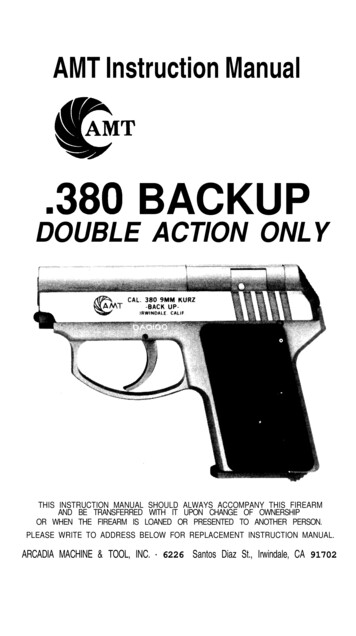
2.SPECIFICATION2.2 The dimensions for Swimming Pool Heat Pump UnitUNIT: P6/32unit:mm320800Water outlet575270Φ50100Water inletΦ50340393UNIT: P8/32/P12/32unit:mm390996Water outlet100Water inlet403603350Φ50Φ505458
2.SPECIFICATION2.2 The dimensions for Swimming Pool Heat Pump UnitUNIT: P14/32P20/32unit mm4601155868Water inletž 50100400Water outletž 50815450UNIT: P23/32P23T/32P26T/32unit mm4251042Water inletž 501004401250Water outletž 509
2.SPECIFICATION45510
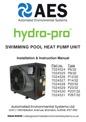
3.INSTALLATION AND CONNECTION3.1 Installation illustrationsupplyInstallation items:The factory only provides the main unit and the water unit; the other items in the illustration arenecessary spare parts for the water system ,that provided by users or the installer.Attention:Please follow these steps when using for the first time1.Open valve and charge water.2.Make sure that the pump and the water-in pipe have been filled with water.3.Close the valve and start the unit.ATTN: It is necessary that the water-in pipe is higher than the pool surface.The schematic diagram is for reference only. Please check the water inlet/outlet label on theheat pump while plumbing installation.The schematic diagram is for reference only. Please check the water inlet/outlet label on theheat pump while plumbing installation.The controller is mounted on the wall11
3.INSTALLATION AND CONNECTION3.2 Swimming Pool Heat Pumps LocationThe unit will perform well in any outdoor location provided that the following three factors arepresented:1. Fresh Air - 2. Electricity - 3. Pool filter pipingThe unit may be installed virtually anywhere outdoors. For indoor pools please consult thesupplier. Unlike a gas heater, it has no draft or pilot light problem in a windy area.500mmDO NOT place the unit in an enclosed area with a limited air volume, where the unitsdischarge air will be re-circulated.DO NOT place the unit to shrubs which can block air inlet. These locations deny the unit of acontinuous source of fresh air which reduces it efficiency and may prevent adequate heatdelivery.Air inletAir outlet3.3 How Close To Your Pool?Normally, the pool heat pump is installed within 7.5 metres of the pool. The longer the distancefrom the pool, the greater the heat loss from the piping. For the most part ,the pipingis buried. Therefore, the heat loss is minimal for runs of up to15 meters(15 meters to and from thepump 30 meters total), unless the ground is wet or the water table is high. A very roughestimate of heat loss per 30 meters is 0.6 kW-hour,(2000BTU) for every 5 difference intemperature between the pool water and the ground surrounding the pipe, which translates toabout 3% to 5% increase in run time.11
3.INSTALLATION AND CONNECTION3.4 Swimming Pool Heat Pumps PlumbingThe Swimming Pool Heat Pumps exclusive rated flow titanium heat exchanger requires nospecial plumbing arrangements except bypass(please set the flow rate according to thenameplate). The water pressure drop is less than 10kPa at max. Flow rate. Since there is noresidual heat or flame Temperatures, The unit does not need copper heat sink piping. PVC pipecan be run straight into the unit.Location: Connect the unit in the pool pump discharge (return) line downstream of all filterand pool pumps, and upstream of any chlorinators, ozonators or chemical pumps.Standard model have slip glue fittings which accept 32mm or 50 mm PVC pipe forconnection to the pool or spa filtration piping. By using a 50 NB to 40NB you can plumb 40NBGive serious consideration to adding a quick coupler fitting at the unit inlet and outlet to allow easydraining of unit for winterizing and to provide easier access should servicing berequired.To poolPVC COUPLERRECOMMENDED(Provided)From pumpCONDENSATIONDRAINBARB FTGCondensation: Since the Heat pump cools down the air about 4 -5 , water may condense on thefins of the horseshoe shaped evaporator. If the relative humidity is very high, this couldbe as much as several litres an hour. The water will run down the fins into the basepan anddrain out through the barbed plastic condensation drain fitting on the side of the basepan. Thisfitting is designed to accept 20mm clear vinyl tubing which can be pushed on by hand and run toa suitable drain. It is easy to mistake the condensation for a water leak inside the unit.NB: A quick way to verify that the water is condensation is to shut off the unit and keep the poolpump running. If the water stops running out of the basepan, it is condensation. ANEVEN QUICKER WAY IS to TEST THE DRAIN WATER FOR CHLORINE - if the is no chlorinepresent, then it's condensation.12
3.INSTALLATION AND CONNECTION3.5 Swimming Pool Heat Pumps Electrical WiringNOTE: Although the unit heat exchanger is electrically isolated from the rest of the unit, itsimply prevents the flow of electricity to or from the pool water. Grounding the unit is stillrequired to protect you against short circuits inside the unit. Bonding is also required.The unit has a separate molded-in junction box with a standard electrical conduit nipplealready in place. Just remove the screws and the front panel, feed your supply lines inthrough the conduit nipple and wire-nut the electric supply wires to the three connectionsalready in the junction box (four connections if three phase). To complete electrical hookup,connect Heat Pump by electrical conduit, UF cable or other suitable means as specified (aspermitted by local electrical authorities) to a dedicated AC power supply branch circuitequipped with the proper circuit breaker, disconnect or time delay fuse protection.Disconnect - A disconnect means (circuit breaker , fused or un-fused switch) should be locatedwithin sight of and readily accessible from the unit, This is common practice on commercial andresidential air conditioners and heat pumps. It prevents remotely-energizing unattended equipmentand permits turning off power at the unit while the unit is beingserviced.3.6 Initial startup of the UnitNOTE- In order for the unit to heat the pool or spa, the filter pump must be running tocirculate water through the heat exchanger.Start up Procedure - After installation is completed, you should follow these steps:1. Turn on your filter pump. Check for water leaks and verify flow to and from the pool.2. Turn on the electrical power supply to the unit, then press the key ON/OFF of wirecontroller, It should start in several seconds.3. After running a few minutes make sure the air leaving the top(side) of the unit iscooler(Between 5-10 )4. With the unit operating turn the filter pump off. The unit should also turn off automatically,5. Allow the unit and pool pump to run 24 hours per day until desired pool water temperatureis reached. When the water-in temperature reaches this setting, the unit will slow down for aperiod of time, if the temperature is maintained for 45 minutes the unit will turn off. The unitwill now automatically restart (as long as your pool pump is running)when the pooltemperature drops more than 0.2 below set temperature.Time Delay- The unit is equipped with a 3 minute built-in solid state restart delay included toprotect control circuit components and to eliminate restart cycling and contactor chatter.This time delay will automatically restart the unit approximately 3 minutes after each controlcircuit interruption. Even a brief power interruption will activate the solid state 3 minuterestart delay and prevent the unit from starting until the 5 minute countdown is completed.13
4.Use and Operation Instruction of Wire Controller4.1. Function of controllerMain display areaOFFONAF minSETTEMPINVOLC3MODESETTEMPOUT2Aux. Display area1451)Button ownFunctionPress this button can start up or shut down the unit,cancel the current operation or back to the upperinterfacePress this button can switch modes or saveparameter setting.Press this button can set the clock and timerPress this button can move up or increaseparameter value.Press this button can move down or decrease theparameter value.14
4.Use and Operation Instruction of Wire ControllerSymbolAMeaningFunctionCoolingIt is showed when the unit in cooling mode.HeatingIt is showed when the unit in heating mode and flashed indefrosting.AutomaticIt is showed when the unit in automatic mode.ElectricheatingIt is showed when the unit in electric-heating mode.(Swimming pool unit without this display)ONTimer onIt is showed when the unit sets the timer onOFFTimer offIt is showed when the unit sets the timer offINInlet waterOUTTEMPIt is showed when the main display area gives the inletwater temperature.(measured value)It is showed when the AUX display area gives the outletOutlet water water temperature.(measured value)Temperature It is showed when the main/ AUX display area givestemperatureIt is showed when the main display area gives the waterflow valueVOLFlowminMinuteFFahrenheitIt is showed when the main/AUX display areagives Fahrenheit valueCCentigradeIt is showed when the main/AUX display areagives centigrade valueParametersettingIt is showed when the parameter can be setted.SETLockIt is showed when the main display area gives minute valueIt is showed when the keyboard is locked.15
4.Use and Operation Instruction of Wire Controller4.2. The controller usage2.1 Starting up and shutting downIn the off interface, press"" for 0.5s can start up the unit, and aux. display-area showswater outlet temperature; In the running interface, press"" for 0.5s can shut down the unitand aux. display-area shows “OFF”.Attention: the operation of Starting up and shutting down can only be done in the main interface. Forexample:Water inlettemperature Water outletWater outletActual Mode tureActual Mode displayCTEMPINfor 0.5 secondcan switchbetween uniton and unit offMODESETTEMPOUTOn unitOff unit2.2 Modes switchingIf it is cold/ heat unit, in the main interface, you can switch different modes of cooling,heating, auto mode by pressing“ SET ”.Attention:The modes switching is useless if the unit you buy is single-cold/ single-heat unit.For example:AMODEPress“ SET”MODESET”TEMPOUTMODESET
4.Use and Operation Instruction of Wire Controller2.3 Temperature settingIn the main interface,press“”or“” and the current mode targettemperature flashes, then press“”to increase the temp.value, or press“”todecrease it.Press“”can save setting parameter and back to the main interface;Press“”can not save setting parameter but back to the main interface;MODESETAttention:If there is no operation for 5s,system would remember parameter setting andback to the main interface.For example:Cooling target MODESETCMODESET”to save value””to change the valueSETCTEMPTEMPOUTsettingMODESETMODESET2.4 Clock settingIn the main interface,press“” twice,Hours start to flashing ,and press“ toincrease value or press“”to decrease value,and press“”to save setting;At the same time, minute start to flashing ,press“”to increase value or press“” to decrease value,and press“”to save setting.Press“”can not save setting parameter and back to main interface.Attention:If there is no operation for 5s system will remember parameter setting and backto the main interface.For example:17
4.Use and Operation Instruction of Wire ControllerHour TSET
4.Use and Operation Instruction of Wire Controller2.5 Timer settingIn the main interface,press“”hold on 2 seconds and "on" is flashing, at this time,you can set the timer on(means the unit timer is on),then press“”again and hold on2 seconds and "off" is flashes you can set the timer off(means the unit timer is off).If you want cancel the timer off, In the "off" flashing”to cancelAttention:1) If there is no operation for 5s,system will remember clock setting and back tothe main interface.2) By pressing" till the "off" flashing, you can set the timer off without timer 9”
4.Use and Operation Instruction of Wire ControllerFlashing CMODESETTEMPOUT”Press“Flashing Flashing”or“Flashing POUTThe timer on and off has been setFlashing TEMPINCTEMPOUT20MODESET
4.Use and Operation Instruction of Wire Controller2.6 Cancel the timer setting”for 2s and "ON" is flashing,at this time, press “Press“”to cancel the settingof timer on; It is the same way to cancel the setting of timer off .For example:The timer on/off has been set"ON" is flashingONOFF”Press“TEMPOUTSETCTEMPINfor 2sPress“”"OFF" is flashingOFFTEMPINTEMPOUTPress“”TEMPOUTThe setting of timer on hasbeen cancelledOFFCPress“MODESETfor 4s”CTEMPINTEMPOUTThe setting of timer off hasbeen cancelledCTEMPINMODESETTEMPOUTMODESET21MODESET
4.Use and Operation Instruction of Wire Controller2.4 Keyboard lockTo avoid mis-operation, please lock the controller after parameter setting.At the main interface, press“”for 5 seconds, the keyboard will be locked. Whenthe keyboard is locked, press“ ”for 5 seconds, the keyboard will beunlocked.NOTES: When the unit is in alarming state, the key lock can be removed automaticly.”Hold on“TEMPOUTTEMPOUTSETSETLocked2.5 Malfunction displayThere will be malfunction code showing on the controller screen when relative malfunctionoccurs.You can refer to the malfunction table to find out the failure cause and solution. For example:MODESET22Water inlet temp. Sensor failure
4.Use and Operation Instruction of Wire Controller4.3. Parameter tableDefaultRemarkHeating inlet target temp.27 AdjustableCooling inlet target temp.27 AdjustableAuto inlet target temp.27 AdjustableMeaningRemark:The wire controller can display the temperature unit as " " or " " according to the unitModel you bought.23
4.Use and Operation Instruction of Wire ControllerTrouble Shooting GuideDisplayCanseWater inlet temp. Sensor failureP01The water inlet temp. Sensor isopen or short circuitCheck or change the waterinlet temp. SensorWater outlet temp. Sensor failureP02The water outlet temp. sensor isopen or short circuitCheck or change the wateroutlet temp. SensorAmbient temp. Sensor failureP04The ambient temp. sensor isopen or short circuitCheck or change theambient temp. SensorPipe temp. Sensor failureP05The pipe temp. sensor isopen or short circuitCheck or change the pipe temp. SensorEvaporator temp.Sensor failureP07The evaporator temp. Sensor isopen or short circuitCheck or change theevaporator temp. SensorHigh pressure protectE01The exhaust pressure is high ,high pressure switch actionCheck high pressure switchand cooling return circuitLow pressure protectE02The suction pressure is low,Low pressure switch actionFlow switch failureE03No water or litter waterin water systemCheck the flow volume ,waterpump is failure or notTemp. is too much differentbetween water-inlet and outletE06Water flow volume not enough,Watersystem pressure difference is smallCheck the flow volume,watersystem is jammed or notAntifreezing under cooling modeE07Water flow volume not enoughCheck the flow volume,watersystem is jammed or notThe primary anti-freezingprotection start.E19Ambient temperature is too lowThe second anti-freezingprotection startE29Ambient temperature is too lowCommunication failureE08Communication failure betweenremote wire controller and main boardMalfunction24SolutionCheck low pressure switch andcooling return circuitCheck the wire connection betweenremote wire controller and main board
4.Use and Operation Instruction of Wire ControllerT5AL250VFUSE4.4. Connection of PCB GNDAI06GNDAI05GNDAI04GNDAI03GNDAI02GNDAI01 5VCN16GNDConnections explanation:No.1Symbol23OUT2MeaningCompressor of system1(220-230VAC)Water pump(220-230VAC)OUT34way valve (220-230VAC)4OUT456OUT57NET GND 12VHigh speed of fan motor(220-230VAC)Low speed of fan motor(220-230VAC)Neutral wireWire controller8DI01 GNDOn/Off Switch(input)(no use)910DI02 GNDDI03 GNDFlow switch (input)( normal close)Low pressure protect111213DI04 GNDHigh pressure protectDI05 GNDDI06 GNDNo useNo use14AI01 GNDSuction temp.(input)1516AI02 GNDWater in temp.(input)AI03 GNDWater out temp.(input)17AI04 GNDTemp. Of coil ( input)18AI05 GNDAmbient temp.(input)19AI06 GNDAdjustable fan speed/Exhaust temperature20CN1Primary transformer21CN2Secondary transformer22CN6Without use23CN19245V CN16 GNDOUT1AC-NElectronic expansion valveFlow meter25
5. MAINTENANCE AND INSPECTIONCheck the water supply device and the release often. You should avoid the condition of nowater or air entering into system, as this will influence unit's performance and reliability.You should clear the pool/spa filter regularly to avoid damage to the unit as a result of the dirtyof clogged filter.The area around the unit should be dry, clean and well ventilated. Clean the side heatingexchanger regularly to maintain good heat exchange as conserve energy .The operation pressure of the refrigerant system should only be serviced by a certifiedtechnician .Check the power supply and cable connection often,.Should the unit begin to operateabnormally, switch it off and contact the qualified technician.Discharge all water in the water pump and water system ,so that freezing of the water in thepump or water system does not occur. You should discharge the water at the bottom of waterpump if the un
2.1 Performance Data of Swimming Pool Heat Pump Unit 4 2.2 Dimensions for Swimming Pool Heat Pump Unit 8 3. Installation and Connection 9 3.1 Installation illustration 9 3.2 Swimming Pool Heat Pumps Location 11 3.3 How Close to Your Pool? 11 3.4 Swimming Pool Heat Pumps Plumbing 12 . 3.5 Swimming Pool Heat Pumps Electrical Wiring 13